
Related Manuals for HELIX DSP ULTRA


Summary of Contents for HELIX DSP ULTRA
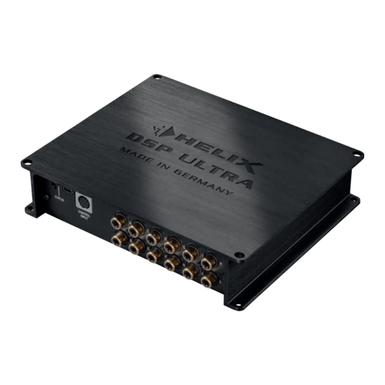
- Page 1 DSP ULTRA Digitaler High-Res 12-Kanal Signalprozessor mit 96 kHz / 32 Bit Signalweg Digital High-Res 12-channel signal processor with 96 kHz / 32 Bit signal path...
-
Page 2: Herzlichen Glückwunsch
Verarbeitung und eine tigen HELIX-Signalprozessors. überzeugende Anwendung ausgereifter Technolo- gien aus. Audiotec Fischer setzt mit dem HELIX DSP ULTRA neue Maßstäbe im Bereich der Signalprozessor- Viel Freude an diesem Produkt wünscht Ihnen das technik. Dabei profitieren Sie als Kunde direkt von Team von unserer nahezu 30-jährigen Erfahrung in der For-... -
Page 3: Anschluss- Und Bedienelemente
Multifunktionsanschluss – dient oder zum Resetten des Gerätes. Anschluss einer Fernbedienung weiterem HELIX Zubehör. Status LED Die Status LED zeigt den Betriebszustand Line Output des Signalprozessors und dessen Speichers Vorverstärkerausgänge zum Anschluss des / der Verstärker/s. Zur Einschaltung eines angeschlossenen Verstärkers muss der USB Eingang Remote-Ausgang verwendet werden. -
Page 4: Optical Input
Eingängen kann aber tung über den Hochpegel-Lautsprechereingang des nur durch eine optionale Fernbedienung DIRECTOR DSP ULTRA aktiviert (Auto Remote = On). oder die WIFI CONTROL erfolgen. Hinweis: Wird die automatische Einschaltung des Signalprozessors deaktiviert, muss der Remote-Ein- 3 Optical Input gang belegt werden. - Page 5 HELIX Diese können im DSP PC-Tool festgelegt werden. DSP ULTRA über das beiliegende Kabel mit dem Wird der Taster länger als fünf Sekunden gedrückt, Computer verbunden und kann anschließend über so wird das Gerät resettet und der gesamte interne...
- Page 6 DSP PC-Tool Software oder an der Fernbedie- DSP PC-Tool Software den Eingängen beliebig zu- nung selbst konfiguriert werden. geordnet werden. Einbau und Installation Der HELIX DSP ULTRA wird wie nachfolgend 2. Anschluss der Highlevel-Lautsprecherein- beschrieben an das Autoradio angeschlossen. gänge Hochpegel-Lautsprechereingänge kön-...
- Page 7 Hinweis: Die Einstellung der Drehregler beein- Das bedeutet, dass an den Signalausgängen flusst sowohl die jeweiligen Vorverstärkerein- des HELIX DSP ULTRA der volle Pegel an- gänge als auch die Highlevel-Eingänge! liegt und die angeschlossenen Verstärker voll Um die Eingangsempfindlichkeit mit Hilfe der ausgesteuert werden.
- Page 8 Pluspol der Batterie oder an einen Stromver- teiler angeschlossen, der mit dem Pluspol der Batterie verbunden ist. Die Stromaufnahme des HELIX DSP ULTRA ist mit ca. 650 mA zwar sehr gering, trotzdem sollten Kabel mit mind. 1 mm² Querschnitt für die Spannungsversor- gung verwendet werden.
- Page 9 Hinweis: Werkseitig ist die automatische Ein- put angeschlossenen Verstärker mit einem Re- schaltung über den Hochpegel-Lautsprecher- mote-Signal zu versorgen. Bitte verwenden Sie eingang des DSP ULTRA aktiviert. ausschließlich dieses Signal zur Einschaltung externer Verstärker, um Ein- und Ausschaltge- räusche zu vermeiden.
-
Page 10: Anschluss An Den Computer
USB-Kabel an den Compu- acht DSP Kanäle separat eingestellt werden. ter an. Wenn Sie längere Distanzen zu über- Bevor Sie den HELIX DSP ULTRA das erste Mal an brücken haben, verwenden Sie bitte eine aktive USB-Verlängerung mit integriertem Repeater einen Computer anschließen, gehen Sie auf unsere... - Page 11 Virtual Channel Processing (VCP) Das Bedienkonzept des VCP Im Gegensatz zu bisherigen Methoden ist das Virtual Channel Processing (VCP) ein mehrstufiges Signalverarbeitungs-Konzept, welches die perfekte Konfiguration komplexer Soundsysteme ermöglicht und somit ganz neue Möglichkeiten des Klangtunings eröffnet. Die Funktion erweitert den bisherigen Umfang des Gerätes um eine neue Ebene an prozessierten Kanälen, welche sich zwischen den Ein- und Ausgängen befindet.
- Page 12 Virtual Channel Processing (VCP) – Kanalübergreifender Gruppen-Equalizer Beispielanwendung: Aktives Mehrwege- System Wird ein Eingangssignal (bspw. Vorne links) erst auf einen virtuellen Kanal geroutet (Front Left) und dieses Signal anschließend auf ein aktives Mehrwege-System geroutet (bspw. Vorne links – Hochtöner, Mitteltöner und Tieftöner) so ist es möglich mit Hilfe des Equalizers des virtuellen Kanals alle nachgeschalteten einzelnen Kanäle gleichzeitig in ihrer Tonalität zu beeinflussen.
- Page 13 Konfiguration des Virtual Channel Processing (VCP) Um das VCP zu konfigurieren, muss zuerst das „Virtual Channel Processing“ im DCM-Menü der DSP PC- Tool Software eingeschaltet werden. Gehen Sie dazu in den „Virtual Channel Processing“-Tab und klicken auf die rechte Box mit der VCP-Grafik. Anschließend erfolgt die Konfiguration in drei Schritten – hier am Beispiel einer 3-Wege Konfiguration mit einem 2-Wege Eingangssignal erläutert.
- Page 14 Konfiguration des Virtual Channel Processing (VCP) Workflow-Schritt 2 – Ausgangsrouting Nachdem alle genutzten Eingangssignale in den jeweiligen Signal-Routing-Matrizen konfiguriert wurden, müssen die virtuellen Kanäle nun den physischen Ausgangskanälen zugeordnet werden. Hierbei kann ein virtuelles Signal (bspw. Front L Full) mehreren Ausgängen zugewiesen werden, wie beispielsweise dem vorderen linken Hochtöner, Mitteltöner und Tieftöner.
- Page 15 Um in den Genuss der DSP-Soundeffekte zu kommen, müssen bei der Hard- und Softwarekonfiguration bestimmte Einstellungen vorgenommen werden. Hinweis: Die DSP-Soundeffekte stehen beim DSP ULTRA nur im Virtual Channel Processing zur Verfü- gung. Dieses kann im DCM-Menü der DSP PC-Tool Software aktiviert werden.
- Page 16 Konfiguration des Virtual Channel Processing (VCP) (Front Links + Front Rechts) oder einem vorhandenen Center-Signal belegt sein. Hinweise zum Eingangsrouting siehe Workflow-Schritt 1 2. Wechseln Sie in die „Virtual to Output Routing“ Matrix und routen den Kanal „Virtual E - Front Center Full“...
- Page 17 ACO Plattform-Features Neben den einzigartigen DSP-Sound effekten bietet „URC Setup Switch Configuration“ festgelegt wer- die ACO-Plattform des DSP ULTRA zusätzlich eine den. Werkseitig sind die Speicherbereiche eins und Vielzahl an System-Features. zwei ausgewählt. Um zwischen allen internen Spei- Im DCM Menü der DSP PC-Tool Software können cherplätzen umschalten zu können, wird die optional...
- Page 18 Einbau einer HELIX Extension Card Der HELIX DSP ULTRA kann durch die Montage 6. Achten Sie auf den richtigen Sitz des HEC Mo- einer HELIX Extension Card (HEC) um weitere duls und darauf, dass alle Kontaktstifte vollstän- Funktionen erweitert werden – beispielsweise um dig im Sockel stecken.
- Page 19 Spezielle Features des HELIX DSP ULTRA TwinDSP Power Start-Stopfähigkeit Der DSP ULTRA beherbergt gleich zwei der lei- Das Netzteil im HELIX DSP ULTRA stellt die interne Spannungsversorgung auch bei kurzfristigen Ein- stungsfähigsten 64 Bit Audio-DSP‘s von Analog brüchen bis hinab zu 6 Volt sicher.
-
Page 20: Technische Daten
Technische Daten Eingänge ..............8 x Cinch 8 x Hochpegel-Lautsprechereingang 1 x Optisch SPDIF-Format (12 - 96 kHz) 1 x Koaxial SPDIF-Format (12 - 192 kHz) 1 x Remote In Eingangsempfindlichkeit ..........Cinch 1 - 8 Volt Hochpegel 4 - 32 Volt Ausgänge .............. -
Page 21: General Instructions
Use only the provided connectors for connec- uct installed by an authorized HELIX dealer. tion of the HELIX DSP ULTRA. The use of other Install your HELIX DSP ULTRA in a dry location connectors or cables can result in damage of... - Page 22 This LED indicates the operating mode of the Line outputs for connecting amplifiers. Make signal processor and of its memory. sure that the remote output is used to turn on these devices. USB input Connects the HELIX DSP ULTRA to your PC.
- Page 23 The sampling rate of this input has to be in the range of 12 and 192 kHz. The DSP ULTRA will be turned on automatically if The input signal is automatically adapted to the in- the Highlevel Input is used or if a signal is applied to ternal sample rate.
- Page 24 12-channel pre-amplifier output for connecting Attention: After erasing the setups from memory po wer amplifiers. The output voltage is 8 Volts the HELIX DSP ULTRA will not reproduce any au- max. Please make sure that you always turn on / dio output.
-
Page 25: Installation
Keep in mind that this will lead to full level on the outputs of the HELIX cause severe damage to the lowlevel line out- DSP ULTRA and your connected amplifiers. - Page 26 6. Adjustment of the ground connection audio source by using the control (The adjust- The signal ground of the HELIX DSP ULTRA is ment will be easier when you connect and ad- galvanically decoupled from the power ground.
- Page 27 DSP PC-Tool software be- block. Though the current draw of the HELIX fore using the signal processor for the first DSP ULTRA is rather low (approx. 650 mA) we recommend a minimum wire gauge of 1 mm² / time.
- Page 28 DSP PC-Tool software have been made. 1. Download the latest version of the DSP Especially if the DSP ULTRA will be used in fully PC-Tool software (available on our website active applications, a wrong setup can destroy your www.audiotec-fischer.com) and install it on...
- Page 29 Virtual Channel Processing (VCP) Operating concept of the VCP In opposite to previous methods the Virtual Channel Processing (VCP) is a multi-stage signal processing concept that enables the perfect configuration of complex sound systems, opening up completely new possibilities for sound tuning. The function extends the previous scope of the device by an additional layer of processed channels, which is located between the inputs and outputs.
- Page 30 Virtual Channel Processing (VCP) – Cross-channel group equalizer Example application: Active multi-way speaker configuration If an input signal (e.g. front left) is first routed to a virtual channel and this signal is then routed to an active multi-way system (e.g. front left – tweeter, midrange and woofer), the group equalizer of the virtual channel will influence all assigned output channels in their tonality.
- Page 31 Configuration of the Virtual Channel Processing (VCP) To configure the VCP, you first have to enable “Virtual Channel Processing” in the DCM menu of the DSP PC-Tool software. Therefore, go to the “Virtual Channel Processing” tab in the DCM menu and click on the right box with the VCP graphic.
- Page 32 Configuration of the Virtual Channel Processing (VCP) Workflow step 2 – Output routing After all the input signals used in the respective signal routing matrix have been configured, the virtual channels must now be assigned to the physical output channels. Here, a virtual signal (e.g. Front L Full) can be assigned to multiple outputs, such as “front left”...
- Page 33 Note: The DSP sound effects are only available in the DSP ULTRA when “Virtual Channel Processing” is enabled. “VCP” can be activated in the DCM menu of the DSP PC-Tool software.
- Page 34 Configuration of the Virtual Channel Processing (VCP) For information about input routing see workflow step 1 2. Change to the “Virtual to Output Routing” matrix and route the “Virtual E - Front Center Full” channel to the desired output channels (as described in workflow step 2) to which the center processing shall be applied.
- Page 35 This function is activated (ON) ex works. system features. ADEP.3 Configuration If the DSP ULTRA is connected to an OEM radio via the highlevel inputs it may happen that the ADEP.3 circuit has to be adapted to the diagnostic mode of the radio if the latter is equipped with a so-called Turn On &...
- Page 36 Streaming module, an additional optical digital input or an USB audio input. To install a HELIX Extension Card it is necessary to remove the side panel of the DSP ULTRA and replace it by the new side panel that comes with the HEC module.
- Page 37 Unique features of the HELIX DSP ULTRA TwinDSP Power Start-Stop capability The DSP ULTRA contains two of the most powerful The switched power supply of the HELIX DSP UL- TRA assures a constant internal supply voltage 64 Bit audio signal processors from Analog Devices with the outstanding overall calculating power of 2.4...
-
Page 38: Technical Data
Technical Data Inputs ................8 x RCA / Cinch 8 x Highlevel speaker input 1 x Optical SPDIF (12 - 96 kHz) 1 x Coaxial SPDIF (12 - 192 kHz) 1 x Remote In Input sensitivity ..............RCA / Cinch 1 - 8 Volts Highlevel 4 - 32 Volts Outputs ................ -
Page 39: Warranty Disclaimer
Warranty Disclaimer The limited warranty comply with legal regulations. Errors are reserved! For damages on the vehicle Failures or damages caused by overload or im- and the device, caused by handling errors of the proper use are not covered by the warranty. Please device, we can’t assume liability. - Page 40 Audiotec Fischer GmbH Hünegräben 26 · 57392 Schmallenberg · Germany Tel.: +49 2972 9788 0 · Fax: +49 2972 9788 88 E-mail: helix@audiotec-fischer.com · Internet: www.audiotec-fischer.com...
Need help?
Do you have a question about the DSP ULTRA and is the answer not in the manual?
Questions and answers