Advertisement
Quick Links
Download this manual
See also:
User Manual
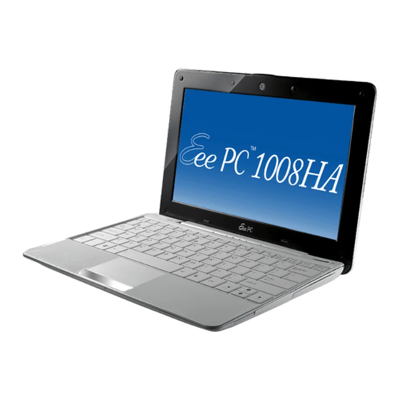
Asus Eee PC 1008HA Seashell Netbook Disassemble Guide.
This disassembly guide is for the
Asus Eee PC
1008HA netbook.
NOTE:
Remember to unplug your power cord and ground yourself before attempting to disassemble
anything. I am not responsible for any damages you do to your netbook. This guide is simply for
references only.
Please also note that replacing your hard drive or ram will automatically void all
manufacture warranties. USE WITH CAUTION!
Original guide and pictures from
(in Italian) and
(in Chinese)
Netbook Italia
Mobile01.com
Keyboard
Use a small flat-head screwdriver to unhook the 4 hooks located on the top of the keyboard. These
hooks are located above the F1, F6, F10 and the Insert keys.
Advertisement

Summary of Contents for Asus Eee PC 1008HA
- Page 1 Asus Eee PC 1008HA Seashell Netbook Disassemble Guide. This disassembly guide is for the Asus Eee PC 1008HA netbook. NOTE: Remember to unplug your power cord and ground yourself before attempting to disassemble anything. I am not responsible for any damages you do to your netbook. This guide is simply for references only.
- Page 2 Gently start prying the keyboard from the top and towards you. Some force may be required due to the keyboard being held down with double-sided tape. Once the keyboard is loosened out, disconnect the connector.
- Page 3 Top Chassis Disassembly Unscrew the 4 screws underneath the netbook as shown below. Remove keyboard (instructions above), unscrew 6 screws shown below (small red circles) and remove the blue connector (big red circle). One of the screws is located under the warranty seal. You will need to break the seal to access the screw.
- Page 4 Slowly pry from one corner to remove the top chassis. Once the top chassis is removed, you should see the inside components of the netbook. 1-Battery, 2-Speakers, 3-System board, 4-Hard drive.
- Page 5 Bluetooth Remove the keyboard and top chassis. The Bluetooth module is located above the left speaker. Pull the BT module out to disconnect it from the system.
- Page 6 Ram & Wireless Card Remove the top chassis as shown above. Disconnect the 3 connectors from the system board (shown in red arrows). Gently lift the system board from the bottom left corner. You will see another connector and will have to disconnect it (arrow).
- Page 7 Remove the black cover over the ram module to reveal the ram. To remove the wireless card, simply unscrew the 2 screws holding down the wireless card, lift it at an angle and slowly wiggle it out.
- Page 8 Image below shows the system board with the fan, wireless card and black cover removed.
- Page 9 Battery Remove the top chassis, disconnect the 3 connectors from the system board and the multi-colored connector from underneath the system board as illustrated in the previous Ram and Wireless Card section. The multi-colored connector is the battery connector to system board. Hard Drive Remove the keyboard, top chassis, system board and battery.
- Page 10 Slowly remove the hard drive from the SATA connector. The connector is on the right of the hard drive. Replacing/upgrading the hard drive is a challenge, since the drive is surrounded with a rubber casing and a styrofoam cushion that seems to be glued on to the hard drive. NB: styrofoam cushion = coussin en mousse de polystyrène...


