
Related Manuals for Delta Amplon MBB RT Series


Summary of Contents for Delta Amplon MBB RT Series
- Page 1 The power behind competitiveness Delta UPS - Amplon Family RT Series, Three Phase 10/ 15/ 20 kVA Maintenance Bypass Box for Single UPS User Manual www.deltapowersolutions.com...
- Page 2 Manual at any time without obligation to notify any person of such revision or changes. Delta will make all possible efforts to secure the accuracy and the integrity of this Manual. Delta disclaims any kinds or forms of warranty, guarantee, or...
-
Page 3: Table Of Contents
Table of Contents Product Introduction ................. 3 Important Safety Instructions ..............4 2.1. Safety Instructions ................4 2.2. Standard Compliance ..............5 2.3. Storage ..................... 5 Package list ....................6 The Rear Panel ................... 8 Installation Procedures ................11 Connection ....................14 6.1. -
Page 4: Product Introduction
Chapter 1 : Product Introduction The Delta Maintenance Bypass Box (MBB) is applicable to Delta Amplon UPSs: RT-15K3P and RT-20K3P. The MBB provides AC input power to the UPS and connects the output of the UPS to the critical loads and is configurable for single- phase or three-phase output to suit your needs. -
Page 5: Important Safety Instructions
Chapter 2 : Important Safety Instructions Important Safety Instructions 2.1. Safety Instructions Installation Warnings • Before installation and usage, please read this User Manual thoroughly. This will help you to use the product correctly and safely. • Install the MBB in a well-ventilated area, away from excess moisture, heat, dust, flammable gas or explosives. -
Page 6: Standard Compliance
least one hour to avoid moisture condensing inside the MBB. • Do not pour and splash any liquid on the MBB. Do not insert any object into the MBB’s slits and openings. Do not put beverage containers on or around the MBB. -
Page 7: Package List
Chapter 3 : Package List 3. Package list The package contains the following items shown in Figure 3-1. Please check if any item is missing. If there is anything missing, please contact the dealer immediately. Model: MBB-RT-15/20K WW2U (Figure 3-1: Package List) Item Quantity 1 PC... - Page 8 NOTE : The cover and screws should be installed on the MBB to protect the power cables as shown in Figure 6-12. There are 3 power cables: main input power cable (4 pins), bypass input power cable (6 pins) and output power cable (6 pins). These three power cables are for connection with the UPS model shipped without the cables already being installed on the UPS;...
-
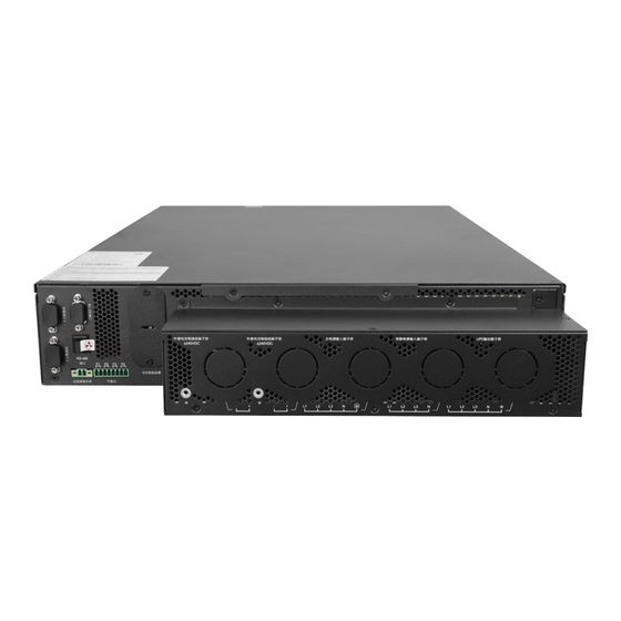
Page 9: The Rear Panel
Chapter 4 : The Rear Panel 4. The Rear Panel NOTE: 1. There are no operational components or interfaces on the front of the MBB. 2. The UPS AC input, the UPS bypass input and the UPS AC output marked with ❷ ❸ ❹ in Figure 4-1 are originally covered, after removing the cover, you can see them and conduct the connection. - Page 10 Item Function Connect to the parallel port of UPS to MBS Port send messages. Connect to the UPS’s AC input power UPS AC Input Port cable. Connect with the UPS’s bypass power UPS Bypass Input Port cable. UPS AC Output Port Connect with the UPS’s output socket.
- Page 11 Include mL1 / mL2 / mL3 (VIN_R) (VIN_S) AC Input Terminals terminals which connect (VIN_T) (IP_N) to the main AC source. Include bL1 / bL2 / bL3 (BYP_R) (BYP_S) Bypass Input Terminals terminals which (BYP_T ) (IP_N) connect to the bypass source. Include L1 / L2 / L3...
-
Page 12: Installation Procedures
Chapter 5 : Installation Procedures 5. Installation Procedures Please follow the steps below to conduct rack mounting: Step ❶ : Attach the included ear brackets to the MBB and verify all screws have been properly fastened. Please see Figure 4-1. (Figure 5-1: Attach the Included Ear Brackets to the MBB) 11 ... - Page 13 See Figure 5-2. (Figure 5-2: Install the MBB to Standard 19-inch Server Rack) NOTE : If the MBB is installed behind the Delta lithium-ion battery pack (optional), please keep MBB away from the Delta lithium-ion battery pack at least 1cm.
- Page 14 UPS or under the UPS depend on installation environment. For example, the MBB is installed under the UPS, see Figure 5-3. (Figure 5-3: Install the MBB under UPS) 13 Amplon RT Series...
-
Page 15: Connection
For more details, please refer to Chapter 6.3.1 ~ Chapter 6.3.4. 2. Regarding the connection between the UPS and the battery pack, please refer to Delta Amplon RT Series 15/ 20kVA UPS User Manual and the Delta battery pack User Manual. 6.1. Pre-connection Warnings The circuit breaker or other protective device must be installed at the AC power input. - Page 16 1. There are an upper cover at the rear of the UPS and three knockout covers on UPS’s rear panel, remove them as shown in Figure 6-1. After removing them, you can see the UPS wiring terminals from the top. (Figure 6-1: Remove the Upper Cover at the Rear of the UPS and the Three Knockout Covers from the UPS’s Rear Panel) 2.
- Page 17 (Figure 6-2: The Connection of Main Input Power Cable with AC Input Terminals of UPS) Step ❷ : Fix the bypass input power cable (6 pins) on the bypass input terminals and grounding terminal of the UPS. Please note that the 6 pins of the bypass input power cable should be connected to the right position of the terminals (bL1, bL2, bL3, N and grounding) as shown in Figure 6-3.
- Page 18 (Figure 6-3: The Connection of the Bypass Input Power Cable with Bypass Input Terminals and Grounding Terminal of UPS) 17 Amplon RT Series...
-
Page 19: Main Input, Bypass Input And Output Connection Of The Mbb
Step ❸ : Fix the included output power cable (6 pins) on the output terminals and grounding terminal of the UPS. Please note that the 6 pins of the output power cable should be connected to the right position of the terminals (L1, L2, L3, N, N and grounding) as shown in Figure 6-4. - Page 20 Regarding the nominal current of the MBB with different phase configurations (single-phase or three-phase), please refer to Table 6-1. Table 6-1: MBB Nominal Current Wiring Nominal Input Phase Nominal Output Phase Current* configuration Current* (Input Phase: Rated Input Voltage Rated Output Voltage Bypass Phase: 220/380V 230/400V...
- Page 21 Table 6-2 lists the minimum cross-sectional area of the cable recommended to the user. You can select the appropriate cables according to Table 6-1 and Table 6-2. Table 6-2: Recommended Cable Size (Environment Temperature: 25°C) Model Neutral Input Output Bypass Ground (Input P: Line...
- Page 22 Table 6-3: Protection Device Capacity Model (Input P: Bypass P: With RT-15K3P With RT-20K3P Output P) 50A/ Type D (main) 63A/ Type D (main) (3:3:3) 50A/ Type D (bypass) 63A/ Type D (bypass) 50A/ Type D (main) 63A/ Type D (main) (3:1:1) 100A/ Type D (bypass) 125A/ Type D (bypass)
- Page 23 The power cable connection of the MBB needs to be connected through the input and output terminals at the rear of the MBB, as shown in Figure 6-5. (Figure 6-5: The Input and Output Terminals of the Rear Panel of the MBB) The wiring terminals include: Item Description...
- Page 24 1. For UPS protective earthing: connects to the main AC source and bypass source* 2. For bonding: connects to the critical loads. Includes one grounding 3. When performing terminal. grounding, please refer to the steps below. For the protective earthing. Please refer to Figure 6- 6 for the connection method.
-
Page 25: Single Source Input & Single Phase Output
(Figure 6-6: the Cable Connection with Protective Earthing Terminal and Protective Bonding Terminal ) The MBB input can be set as single-source input or dual-source input and the MBB output can be set as three-phase or single-phase, which depends on the way you install the bus bars (provided in the package) and the output phase setting. -
Page 26: Dual Source Input & Single Phase Output
(Figure 6-7: MBB Bus Bar Installation for Single Source Input & Single Phase Output Configuration) 6.3.2. Dual Source Input & Single Phase Output 1. Install the bus bars by following Figure 6-8. 2. Connect to AC source (L1/ L2/ L3/ N): connect L1 to mL1; L2 to mL2; L3 to mL3; to one of the N terminals. -
Page 27: Dual Source Input & Three Phase Output
(Figure 6-8: MBB Bus Bar Installation for Dual Source Input & Single Phase Configuration) 6.3.3. Dual Source Input & Three Phase Output 1. Install the bus bars following Figure 6-9. 2. Connect to AC source (L1/ L2/ L3/ N): connect L1 to mL1; L2 to mL2; L3 to mL3; to one of the N terminals. -
Page 28: Single Source Input & Three Phase Output
(Figure 6-9: MBB Bus Bar Installation for Dual Source Input & Three Phase Output Configuration) 6.3.4. Single Source Input & Three Phase Output 1. Install the bus bars by following Figure 6-10. 2. Connection to AC source (L1/ L2/ L3/ N): connect L1 to mL1or bL1; L2 to mL2 or bL2;... -
Page 29: Connection Of The Mbb And The Ups
(Figure 6-10: MBB Bus Bar Installation for Single Source Input & Three Phase Output Configuration) 6.4. Connection of the MBB and the UPS Insert three power cables of UPS to the ports on MBB’s rear panel. Please see steps ❶ ❷ ❸ in Figure 6-11. Install the two ends of the provided MBB communication cable on the MBB’s MBS port and the UPS’s parallel port. - Page 30 (Figure 6-11: Installation for the Power Cables and the MBB’s Communication Cable) Install the provided cover on power cables and tighten the provided screws (both are included in the package). Please see the step in Figure 6-12. (Figure 6-12: Installation for the Provided Cover) 29 ...
- Page 31 NOTE: For the MBB connection, the power cables and cable glands must have been installed on the UPS before the UPS is shipped. However, this depends on different UPS model requirements. As the MBB is optional, if the user purchased the UPS model without the power cables and cable glands already installed on the UPS before shipment, the three power cables need to be connected to the UPS’s wiring terminals (including the AC input terminals, bypass input terminals,...
-
Page 32: Operation Procedures
Make sure the voltage, the frequency and the phase sequence of the input and the bypass are in the operation range. Turn on the main input and bypass input breaker. Follow Delta Amplon RT Series 15/ 20kVA UPS User Manual to turn on the UPS. 31 ... -
Page 33: Maintenance Bypass
Chapter 8 : Maintenance Bypass 8. Maintenance Bypass Follow the steps to let the output load powered by manual bypass when UPS needs maintenance. Check the UPS is at bypass mode, if not, press and hold the UPS’s ON/ OFF button for 3 seconds, release it after you hear one beep, use the Scrolling Up or Down button to select 'Yes' and press the Enter button to confirm your selection. - Page 34 Under the cover plate, there is a manual bypass detector (see Figure 8-2) that will be automatically activated to send the UPS a message of transferring into bypass mode once the cover plate is removed. After you confirm that the UPS has been run in bypass mode, turn on the manual bypass switch.
- Page 35 Communication Cable from the Rear Panel of MBB.) NOTE: You should remove the connection between the MBB and the UPS before disconnecting the battery pack with the UPS. Regarding the disassembly of the battery pack, please refer to the Delta battery pack User Manual. 34 ...
-
Page 36: Appendix 1 : Technical Specifications
Appendix 1 : Technical Specifications Appendix 1 : Technical Specifications Model MBB-RT-15/20K WW2U Nominal Voltage 220/380, 230/400, 240/415 Vac Nominal Current 35, 34.1, 32.3 A Input Connection Terminal block Nominal Voltage 220/380, 230/400, 240/415 Vac 30.6, 29.3, 28.1 A per phase; Number of Phases: 3Ф... - Page 37 0 ~ 3000m; Operating Altitude 0 ~ 1000m (without derating) 0°C ~ 55°C Operating Temperature* Environment Storage Temperature -15°C ~ 55°C Relative Humidity 5% ~ 95% (non-condensing) NOTE: When the operating temperature is at 40 ~ 55°C, the UPS will be derated to 75% of its capacity.
-
Page 38: Appendix 2 : Warranty
Appendix 2 : Warranty Appendix 2 : Warranty Seller warrants this product, if used in accordance with all applicable instructions, to be free from original defects in material and workmanship within the warranty period. If the product has any failure problem within the warranty period, Seller will repair or replace the product at its sole discretion according to the failure situation. - Page 39 - Regional Office The United States Australia Delta Electronics (Americas) Ltd. Delta Energy Systems Australia Pty Ltd. 46101 Fremont Blvd. Fremont, CA 94538 Unit 20-21, 45 Normanby Road, Notting Hill VIC 3168, Australia T +1 510 344 2157 T +61 3 9543 3720 E ups.na@deltaww.com...
- Page 40 5013275001...