Advertisement
Quick Links
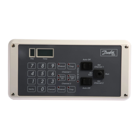
Seven Day Two Channel Electronic Timeswitch
Model 852
Installation and Wiring Instructions
The model 852 timeswitch must be installed by a competent
electrician and the installation should conform to IEE Wiring
Regulations.
Installation and Wiring
1
Slacken the four fi xing screws, one in each corner
of the unit, and carefully separate the front and rear
portions. Unplug the ribbon cable from the rear portion.
CAUTION: Do not allow either half of the unit to hang
by the ribbon cable as damage could be caused.
2
Remove the polystyrene packing piece from the top
of the transformer. It is marked "REMOVE".
3
Select the desired fi xing position and observe the label
"THIS WAY UP" inside the rear portion. The two halves
will only assemble correctly one way round.
4
Four fi xing holes are provided for attaching the rear
portion to the wall or mounting surface.Conduit box
adaptors as shown below are availabe if required.
PART NO: 8/3222 Square Conduit Box Adaptor
CABLE
ENTRY
APERTURE
4 fixings for existing
square conduit box
PART NO: 8/3223 Double Gang Surface Box Adaptor
CABLE
ENTRY
APERTURE
2 fixings for
double gang
surface box
5
Surface cable entries to the unit can be made from
above, below or from the lefthand side. Conduit or
recessed cable entry is through the aperture in the
rear moulding.
4 fixings for
MK8 timeswitch
Alternative 4 fixings
4 fixings
for double gang
for MK8
surface box
timeswitch
6
For surface cable entry remove the appropriate
knockout and ensure one of the cable clamps is
positioned correctly.
7
Connections to the unit should be made as shown
below:
N
L
6
230V 50Hz
Mains Supply
OFF
Channel 2
If the control circuits are to operate at 240V then
terminals L, 1 and 4 must be linked, ensuring that the
cable is sheathed and of a size to carry the required
load current.
If the control circuits are operating at voltages other
than 230V then terminals 1 and 4 should be connected
to the required power supply and not to terminal L.
8.
Upon completion of wiring, plug in the ribbon cable
ensuring the polarised plug is fully inserted into the
socket. Refi t the front half of the timeswich ensuring
correct alignment and that no cables are trapped before
re-tightening the screws.
N
L
6
5
4
3
2
Links for 230V
control
circuit(s)
ON
OFF
Channel 1
1
ON
1
Advertisement

Related Manuals for Danfoss 852


Summary of Contents for Danfoss 852
- Page 1 Seven Day Two Channel Electronic Timeswitch Model 852 Installation and Wiring Instructions The model 852 timeswitch must be installed by a competent electrician and the installation should conform to IEE Wiring Regulations. Installation and Wiring For surface cable entry remove the appropriate Slacken the four fi...
- Page 2 Danfoss Randall can accept no responsibility for possible errors in catalogues, brochures and other printed material. Danfoss Randall reserves the right to alter its products without notice. This also applies to products already on order provided that such alterations can be made without subsequent changes being necessary in specifi...