Table of Contents
Advertisement
Quick Links
2i
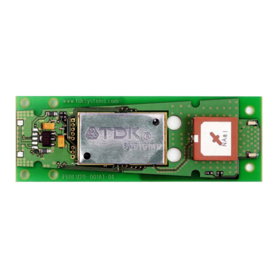
blu
Module
User Guide
The information contained in this document is subject to change without notice. TDK Systems Europe makes no warranty of
any kind with regard to this material including, but not limited to, the implied warranties of merchant ability and fitness for a
particular purpose. TDK Systems Europe shall not be liable for errors contained herein or for incidental or consequential
damages in connection with the furnishing, performance, or use of this material.
© Copyright 2004 TDK Systems Europe Limited.
All rights reserved.
This document contains information that is protected by copyright. All rights reserved. No part of this document may be
photocopied, reproduced, or translated to another language without the prior written consent of TDK Systems Europe.
Other product or company names used in this publication are for identification purposes only and may be trademarks of their
respective owners.
1 of 36
Advertisement
Table of Contents

Related Manuals for TDK Module blu2i


Summary of Contents for TDK Module blu2i
-
Page 1: User Guide
User Guide The information contained in this document is subject to change without notice. TDK Systems Europe makes no warranty of any kind with regard to this material including, but not limited to, the implied warranties of merchant ability and fitness for a particular purpose. -
Page 2: Table Of Contents
TATUS IGNALS GETTING STARTED ... 30 8.1.1 Two blu Modules... 30 8.1.2 One blu Module and Bluetooth PC using TDK’s USB Adaptor or PC Card... 31 ... 32 ACTORY EFAULT ... 32 OFTWARE APPENDIX A ... 34 – EU D... -
Page 3: Before You Begin
Bluetooth and regulatory approvals. A list of the countries where the module is approved will be provided by TDK Systems as required. As a minimum the product is listed in Europe, Scandinavia and USA. TDK Systems assumes no liability for customer failure to comply with national RF approvals. -
Page 4: Functions
Functions The blu Module contains a complete Bluetooth interface and requires no further hardware to implement full Bluetooth communication. The module has an integrated, high performance antenna together with all RF and Baseband circuitry, it interfaces to the host over a straight forward serial port using AT commands. -
Page 5: Application Interface
Application Interface The blu Module is equipped with a 40-pin 0.5mm pitch board to board connector that connects to the application platform. Electrical and mechanical characteristics of the board-to-board connector are specified in Chapter 3. • Serial interface (see Section 3.0) •... -
Page 6: Power Supply
Module UART_TX UART_RX UART_CTS UART_RTS UART_DTS UART_DTR UART_DCD UART RI Figure: UART interfaces 2.2 Power Supply The power supply for the blu of Vcc= 3.6V to 6V. It must be able to provide sufficient current in a transmit burst which can rise to 65mA. The module includes regulators to provide local 3.3V and 1.8V. - Page 7 example when the supply voltage to the module experiences a Brown- Out (momentary dip in the supply voltage level), or a rapid power cycle i.e. the power is switched off and then on within 1second, there is a possibility that the module can enter an unknown state of operation. It is strongly recommended that the application hardware onto which the module is mounted provides a Power-On-Reset circuit with a Brown-Out detection capability.
-
Page 8: Spi Bus
2.4 SPI Bus The module is a slave device that uses terminals SPI_MOSI, SPI_MISO, SPI_CLK and SPI_CSB. This interface is used for program firmware update. Note: The designer should be aware that no security protection is built into the hardware or firmware associated with this port, so the terminals should not be permanently connected in a PC application. -
Page 9: Electrical Specification Of The Interface
Electrical specification of the interface The Hirose DF12C board to board connector on the module is a 40 way double-row receptacle. The pin allocation is as follows: Signal Description Analogue 0 1.8v Max Analogue 1 1.8v Max SPI_MISO SPI bus serial SPI_CSB SPI bus chip select I/P... - Page 10 Notes: • UART_RX, UART_TX, UART_CTS, UART_RTS, UART_RI, UART_DCD and UART_DSR are all 3.3v level logic. For example, when RX and TX are idle they will be sitting at 3.3V. Conversely for handshaking pins CTS, RTS, RI, DCD, DSR a 0v is treated as an assertion.
-
Page 11: Electric Characteristics
3.1 Electric Characteristics Function Signal Name Pin No Power Supply 11, 15, 18, 30, 36, 38 RS232 UART_TX Interface UART_RX UART_CTS UART_RTS UART_DSR UART_DTR UART_RI UART_DCD External VCC_1V8 Power Supply VCC_3V3 SPI Bus SPI_MOSI SPI_MISO SPI_CSB SPI_CLK Signal level 3.6V to 6V max=0.2V min=2.8V max=0.8V... - Page 12 PCM_CLK Interface PCM_IN PCM_SYNC PCM_OUT Reserved BC02 USB D- BC02 USB D+ GPIO GPIO 1 - 5 2,4,12, 14,16 Analog AIO_0, 1, 3 AIO_1 Reset RESET min=2.10V max=3.7V I or O O/P : V max=0.2V min=2.8V I/P : V max=0.8V min=2.10V max=3.7V max=0.8V...
-
Page 13: Physical Characteristics
Physical Characteristics 4.1 Mechanical Dimensions 13 of 36... -
Page 14: Mounting The Blu
4.2 Mounting the blu platform There are many ways to properly install the Module in a host device. An efficient approach is to mount the PCB to a frame, plate, rack or chassis. Fasteners can be M1.8 or M2 screws plus suitable washers, circuit board spacers, or customized screws, clamps, or brackets in 2.2mm diameter holes. - Page 15 Mating headers from Hirose are available in different stacking heights. Details are available at: http://www.hirose.co.jp/cat2002e/500/e53700036.pdf Item Part number Headers DF12(3.5)-40DP- DF12 series 0.5V(81) DF12(4.0)-40DP- 0.5V(81) DF12(5.0)-40DP- 0.5V(81) Note: The headers listed above are without boss and metal fitting. Electrical and mechanical characteristics of the Hirose DF12C connector: Parameter Number of Contacts...
-
Page 16: Electrical And Radio Characteristics
Electrical and radio characteristics 5.1 Absolute Maximum ratings Absolute maximum ratings for supply voltage and voltages on digital and analog pins of the module are listed below. Exceeding these values will cause permanent damage. Peak current of power supply Voltage at digital pins Voltage at POWER pin 5.2 Operating temperatures Operating temperature... - Page 17 being transferred and when data is being transferred at the maximum rate possible. The operating mode can best be described by stating the AT commands required to enter that mode. In addition, there are certain S Registers which have a direct impact on power consumption, which are described next.
- Page 18 Current per LED Idle Mode, S512=1 Wait for Connection Or Discoverable Mode, AT+BTP S508=S510=640, S509=S511=320 Wait for Connection Or Discoverable Mode, AT+BTP S508=S510=1000, S509=S511=11 Inquiring Mode, AT+BTI Connecting Mode (ATDxxx) Connected as Master Mode (No Data Transfer) Sniff NOT activated Connected as Master Mode (Max Data Transfer)
-
Page 19: Low Power Modes Using Sniff
It is possible to reduce the duty cycle down to as low as 0.5% at the expense of response time. The response time can be specified via S Registers 508 and 510 for page and inquiry respectively, where the worst case response time can be as high as 2.5 seconds. Then the duty cycle can be varied by changing the value of S Registers 509 and 511 appropriately. - Page 20 This will allow the master to interleave the sniff modes for all slaves attached. For this reason, the sniff parameters are specified in TDK module via four S registers. S Register 561 is used to specify ‘N’, S Register 562 is used to specify ‘T’...
-
Page 21: Rf Performance
5.5 RF performance 5.5.1 Transmit Power Conducted Transmit Power: Antenna Gain: Effective Transmit Power: 5.5.2 Receive Sensitivity Receive Sensitivity: Antenna Gain: Effective Receive Sensitivity: -40 deg -20 deg 0 deg -100 5.5.3 Range See Data Transfer Rate vs distance. The data throughput of the blu Module is limited to 200Kbps by the parsing of the data being transferred through the AT command processor. -
Page 22: Performance Against Temperature
case data though-put with and without the AT command processing. Distances are measured in free space between 2 blu 100m 5.5.4 Performance against Temperature Data Transmit Rate with Temperature and Attenuation -60dBm -65dBm -70dBm Modules. Data Transfer Rate / Distance 150m 200m 250m... -
Page 23: Reliability
5.6 Reliability Parameter Thermal Shock Vibration Shock Moisture Resistance High Temp Storage Low Temp Storage High Temp/Humidity Operation High Temp/Humidity Storage Thermal shock Electro Static Discharge Drop Test Minimum Maximum 200cycles -40ºC 1 cycle/hour /+85ºC 30 min Continuous operation 15g max sine wave, at 60 Hz, 2mm stroke 12 hours 50G 11ms Half Sine... -
Page 24: Rs232 Modem Signals
RS232 Modem Signals Just as a telephony modem has control and status lines, the blu also provides for 6 control and status lines as per the table below. The direction column is as seen from the modules viewpoint. Direction IN or OUT IN or OUT The first four lines are under program control and as such require GPIO pins and they are mapped to I/O as per the table below. -
Page 25: Modem Signalling Over Bluetooth
specified in S Register 519 then the connection is dropped as if an ATH command was received. PIO2 (RI), is normally deasserted. When an incoming connection is detected it will be asserted, until the connection is either answered or rejected using ATA and ATH respectively. See S Registers 552 & 553 for more details PIO3 (DCD) will be deasserted when the device is in the unconnected state. -
Page 26: Reset
Future enhancement may allow the BREAK signal to be used to map to GPIO which with appropriate external hardware may allow for a BREAK to be reproduced on the TX line. 6.3 Reset The module can be reset by the host without the need of any I/O using a BREAK signal. -
Page 27: Pure Cable Replacement Mode
Pure Cable Replacement Mode 7.1 Data Cable The module has the capability of being preset into a pure 5-wire data cable replacement mode. The 5 wires being RX, TX, CTS, RTS and GND. This mode requires no changes to a host application since the Bluetooth connection is automatically set up on power up and will retry when the connection drops. -
Page 28: Audio Cable
Where <bdaddr_m> is optional. If it is not specified, then the slave unit will accept connections from any device. If specified then only connections from the device specified will be accepted. If it is desired that the slave unit not be discoverable (the master is by default not discoverable), then the configuration commands are, AT&F ATS512=3... -
Page 29: Modem Control And Status Signals
ATS504=1 ATS530=2000 ATS532=1 AT&W AT+BTR<bdaddr_s> And the slave is configured by, AT&F ATS512=4 ATS0=-1 AT&W AT+BTR<bdaddr_m> 7.3 Modem Control and Status Signals A serial port has DTR, DSR, RTS, CTS, DCD and RI control lines. RTS and CTS are locally controlled to prevent local buffer overflow. However the status of DTR, DRS, DCD and RI can be exchanged with the remote peer device. -
Page 30: Getting Started
Bluetooth hardware:- Two blu Modules. One blu Module and a Bluetooth Enabled PC using TDK’s Go Blue USB Adaptor or PC Card. Note: The following examples assume that a PC is used to control the Module using a Terminal Emulation application. -
Page 31: One Blu 2I Module And Bluetooth Pc Using Tdk's Usb Adaptor Or Pc Card
Module attached and the latest Windows Bluetooth stack from TDK installed. Also confirm that the TDK Go Blue USB Adaptor or PC Card is connected to your PC and that it is functional. You can confirm this by checking that the Bluetooth icon in the system tray area has a White B on a blue background. -
Page 32: Factory Default Mode
HyperTerminal, Procomm or the TDK Terminal application supplied are all suitable terminal emulators. TDK Terminal is a terminal emulation application capable of running on Windows 98, Me, 2000 and XP operating systems. It was developed specifically to aid development and testing of the blu Module. - Page 33 Data Bits: 7 or 8 Stop Bits: 1 or 2 Handshaking: None or CTS/RTS The unique benefits of using TDK Terminal are: • Status of DSR, CTS, DCD and RI are continuously displayed • DTR can be directly controlled via a check box •...
-
Page 34: Europe - Eu Declaration Of Conformity
Protection requirements with respect to electromagnetic compatibility Art.3 (1) b) Means of the efficient use of the radio frequency spectrum & & TDK Systems Europe Ltd tel: +44 (0)20 8938 1000 126 Colindale Avenue, Colindale fax: +44 (0)20 8905 8608 London NW9 5HD, United Kingdom www.tdksys.com... -
Page 35: Esd (Electrostatic Discharge)
Appendix B ESD (Electrostatic Discharge) If your TDK Bluetooth device is affected by ESD, it is recommended that you restart any Bluetooth processes that were active at the time. Additional Statement TDK SYSTEMS' BLUETOOTH PRODUCTS ARE NOT AUTHORISED FOR USE AS CRITICAL COMPONENTS IN LIFE SUPPORT DEVICES OR SYSTEMS WITHOUT THE EXPRESS WRITTEN APPROVAL OF THE MANAGING DIRECTOR OF TDK SYSTEMS EUROPE. -
Page 36: Warranty
In no event shall TDK be liable, whether in contract, in part, or on any other basis, for any damage sustained by its customers or any other person arising from or...