Danfoss DHP-A Installation Instructions Manual
Hide thumbs
Also See for DHP-A:
- Service instructions manual (86 pages) ,
- Installation manual (64 pages) ,
- User manual (31 pages)

Related Manuals for Danfoss DHP-A


Summary of Contents for Danfoss DHP-A
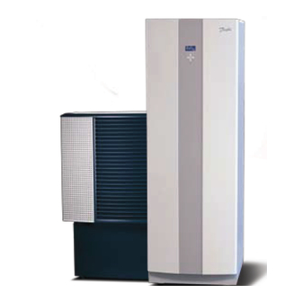
- Page 1 Installation instruc- tions DHP-A DHP-A Opti DHP-AL DHP-AL Opti DHP-C DHP-H DHP-H Opti DHP-H Opti Pro DHP-L DHP-L Opti DHP-L Opti Pro VMBMA1002...
- Page 2 If these instructions are not followed during installation and service, Danfoss A/Sliability according to the applicable warranty is not binding. Danfoss A/S retains the right to make changes to components and specifications without prior notice. © 2010 Copyright Danfoss A/S.
-
Page 3: Table Of Contents
DHP-L, DHP-L Opti............... 11 DHP-L Opti Pro................12 DHP-A, DHP-A Opti..............12 DHP-AL, DHP-AL Opti..............13 Outdoor unit DHP-A, DHP-AL, DHP-A Opti, DHP-AL Opti. 14 Transport, unpacking and setting-up........15 Transporting the heat pump........... 15 Unpacking heat pump............... 15 Setting-up the heat pump............15 Setting-up the outdoor unit............ -
Page 5: About Documents And Decals
Supplied with the heat pump on delivery. The Service instructions and Electrical instructions are available for download here: www.documentation.heatpump.danfoss.com Symbols in documents The instructions contain different warning symbols, which, together with text, indicate to the user that there are risks involved with actions to be taken. - Page 6 Warning, danger! Read the documentation provided. Read the documentation provided. Warning, hazardous electrical voltage! Warning, hot surfaces! Warning, moving parts! Warning, risk of crushing injury! Electrical components Component, normal Component, accessory Outdoor unit Drip tray Outdoor sensor Shunt valve Hot water sensor Room sensor Sensor hot-water top Flow guard...
- Page 7 Pipe connections Tap water Heating system Brine Defrosting tank Expansion tank with safety valve, brine Bleeding Temperature and pressure relief valve Outdoor unit Water heater Installation instructions VMBMA1002 – 5...
-
Page 8: Important Information/Safety Regulations
Service menu. Warning! Danfoss SP (1-phase) heat pumps have a factory installed safety valve for temperature and pressure, (10 bar 90-95°C), in accordance with the requirements in Great Britain. This valve is located in the water tank and may not be used for any purpose other than connecting the outlet pipe. -
Page 9: Refrigerant
Caution! The hot water tank must be equipped with an approved safety valve. Caution! Heating systems with closed expansion tanks must also be supplied with approved pressure gauges and safety valves. Caution! Cold and hot water pipes and overflow pipes from safety valves must be made of heat resistant and corrosion-resistant material, e.g. -
Page 10: Electrical Connection
Draining and refilling must only be carried out using new refrigerant (for the amount and type of refrigerant see manufacturer’s plate) through the service valves. Caution! All warranties from Danfoss are void if, when filling with refrigerant other than Danfoss A/S specified refrigerant, if there has not been written notification that the new refrigerant is an approved replacement refrigerant together with other remedies. - Page 11 Caution! If the installation is only to be driven by an auxiliary heater during the installation, ensure that the heating system is filled and the brine pump and compressor cannot be started. This is carried out by setting the operating mode to AUX. HEATER. Installation instructions VMBMA1002 –...
-
Page 12: Heat Pump Data, Dimensions And Connections
Heat pump data, dimensions and connections DHP-H, DHP-H Opti Symbol explanation Brine in, 28 Cu Brine out, 28 Cu Heating system supply pipe, 22 Cu: 4-10 kW, 28 Cu: 12-16 kW Heating system return pipe, 22 Cu: 4-10 kW, 28 Cu: 12-16 kW Connection for bleed valve, 22 Cu Hot water line, 22 mm Cold water line, 22 mm... -
Page 13: Dhp-C
DHP-C Symbol explanation Brine in, 28 Cu Brine out, 28 Cu Heating system supply pipe, 22 Cu Heating system return pipe, 22 Cu Connection for bleed valve, 22 Cu Hot water line, 22 mm Cold water line, 22 mm Lead-in for supply, sensor and communication cables The brine pipes can be connected on either the left or right-hand sides 40±10 of the heat pump. -
Page 14: Dhp-L Opti Pro
The brine lines (2), (3) and return line water heater (1) can be connected on the right or left-hand sides. Figure 4. Dimensions and connections DHP-A, DHP-A Opti Symbol explanation Brine in, 28 Cu Brine out, 28 Cu Lead-in for supply, sensor and communication cables... -
Page 15: Dhp-Al, Dhp-Al Opti
DHP-AL, DHP-AL Opti The brine pipes can be connected on either the left or right-hand sides of the heat pump. 40±10 40±10 Figure 6. Dimensions and connections heat pump and water heater Symbol explanation Heat pump Brine in, 28 Cu Heating system supply pipe, 22 Cu: 6-10 kW, 28 Cu: 12 Brine out, during normal operation, 28 Cu Heating system return pipe, 22 Cu: 6-10 kW, 28 Cu: 12 kW... -
Page 16: Outdoor Unit Dhp-A, Dhp-Al, Dhp-A Opti, Dhp-Al Opti
Outdoor unit DHP-A, DHP-AL, DHP-A Opti, DHP-AL Opti 1175 Figure 7. Outdoor unit, dimensions and connections. Symbol explanation Brine in, 28 Cu Brine out, 28 Cu 14 – Installation instructions VMBMA1002... -
Page 17: Transport, Unpacking And Setting-Up
Transport, unpacking and setting-up Transporting the heat pump Caution! During transportation or lifting of the entire heat pump, the front panel must always be installed as it locks the other panels construction. Caution! The heat pump must always be transported and stored in a dry area. Secure the heat pump so that it cannot tip over during transportation. - Page 18 Avoid positioning the heat pump in a corner as the surrounding walls may amplify its noise. It is also important to adjust the heat pump using the adjustable feet so that it is horizontal to the base. 4.3.2 Space requirement Caution! The heat pump must not be enclosed as the temperature inside the cabinet becomes extremely high.
-
Page 19: Setting-Up The Outdoor Unit
Press against the front cover and turn the catch 90° degrees anti-clockwise to release the front cover. Tilt the front cover outwards. Lift the front cover upwards to remove it from the heat pump. Setting-up the outdoor unit Note! Applies to DHP-A. 4.4.1 Recommended location When positioning the outdoor unit, note the following: Caution! When the outdoor unit is defrosting, water will drip straight down under the unit. - Page 20 4.4.2 Space requirement 300 mm 300 mm 300 mm 1500 mm Figure 9. Necessary service space for outdoor unit. 4.4.3 Unpacking The outdoor unit is packed and delivered in a crate. Start by unpacking the unit from the crate. Check that the delivery is complete, it must contain the outdoor unit, front cover, cover as well as a disas- sembled stand including necessary screws, nuts and washers.
- Page 21 There are three M6x20 screws on the lower edge of the outdoor unit. Unscrew them so that 2-3 mm of the thread remains. Use a torx TX25 screwdriver, or equivalent. Caution! Do not lift the outdoor unit by its side panels when it is to be raised or moved. Raise the outdoor unit.
- Page 22 Secure the front panel's upper edge with the 2 x remaining M6x15 torx TX25, see figure below. Figure 12. Secure the cover 4.4.4.6 Install the cover Hook the cover at the front edge on the front cover. Figure 13. Hook the front cover into place Secure the cover using a screw on each side.
- Page 23 4.4.4.7 Install cover Hook the cover onto the stand. Figure 15. Hook the cover onto the stand. Installation instructions VMBMA1002 – 21...
-
Page 24: Piping Installation
Service menu. Warning! Danfoss SP (1-phase) heat pumps have a factory installed safety valve for temperature and pressure, (10 bar 90-95°C), in accordance with the requirements in Great Britain. This valve is located in the water tank and may not be used for any purpose other than connecting the outlet pipe. -
Page 25: Connection Heat Transfer Fluid
For system solution 1, select the factory setting in menu SERVICE\AUX. HEATER\EXTERNAL ADDITION: EXTERNAL AUX. HEATER = 0 (Off) REV.V. HOT WATER = INT 5.2.1.1 Example system solution 1 System solution for DHP-H, DHP-H Opti, DHP-H Opti Pro, DHP-C, DHP-A, DHP-A Opti. Symbol explanation Heat pump Supply line... - Page 26 5.2.1.2 Example system solution 1 System solution for DHP-L, DHP-L Opti Symbol explanation Heat pump Supply line Return line Cold water Hot-water Water heater Shut-off valve Non-return valve Venting valve Safety valve expansion heating system Safety valve cold water 9 bar Vacuum valve Strainer Flexible hose...
- Page 27 5.2.1.3 Example system solution 1 System solution for DHP-L Opti Pro. Symbol explanation Heat pump Supply line Return line Cold water Hot-water Water heater Shut-off valve Non-return valve Venting valve Safety valve expansion heating system Safety valve cold water 9 bar Vacuum valve Strainer Flexible hose...
- Page 28 For system solution 2, select in menu SERVICE\AUX. HEATER\EXTERNAL ADDITION: EXT.AUX.HEATER = ON REV.V. HOT WATER = INT 5.2.2.1 Example system solution 2 System solution for DHP-H, DHP-H Opti, DHP-H Opti Pro, DHP-C, DHP-A, DHP-A Opti. Symbol explanation Heat pump Supply line...
- Page 29 5.2.2.2 Example system solution 2 System solution for DHP-L, DHP-L Opti. Symbol explanation Heat pump Supply line Return line Cold water Hot-water Water heater Circulation pump Supply line sensor, moved out from heat pump Additional shunt Shut-off valve Non-return valve Venting valve Safety valve expansion heating system Figure 21.
- Page 30 5.2.2.3 Example system solution 2 System solution 2 for DHP-L Opti Pro. Symbol explanation Heat pump Supply line Return line Cold water Hot-water Water heater Circulation pump Supply line sensor, moved out from heat pump Additional shunt Shut-off valve Non-return valve Venting valve Safety valve expansion heating system Safety valve cold water 9 bar...
- Page 31 5.2.2.4 Example system solution 2 System solution for DHP-AL, DHP-AL Opti. Symbol explanation Heat pump Supply line Return line Cold water Hot-water Water heater (DHP-AL) Circulation pump Supply line sensor, moved out from heat pump Additional shunt Shut-off valve Non-return valve Venting valve Safety valve expansion heating system Safety valve cold water 9 bar...
- Page 32 5.2.3.1 Example system solution 3 System solution for DHP-H, DHP-H Opti, DHP-C, DHP-A, DHP-A Opti. Symbol explanation Heat pump Supply line Return line Cold water Hot-water Circulation pump Supply line sensor, moved out from heat pump Additional shunt Reversing valve...
- Page 33 5.2.3.2 Example system solution 3 System solution for DHP-L, DHP-L Opti. Symbol explanation Heat pump Supply line Return line Cold water Hot-water Water heater Circulation pump Supply line sensor, moved out from heat pump Additional shunt Reversing valve Shut-off valve Non-return valve Venting valve Figure 25.
- Page 34 5.2.3.3 Example system solution 3 System solution for DHP-AL, DHP-AL Opti. Symbol explanation Heat pump Supply line Return line Cold water Hot-water Water heater (DHP-AL) Circulation pump Supply line sensor, moved out from heat pump Additional shunt Reversing valve Shut-off valve Non-return valve Venting valve Figure 26.
-
Page 35: Connection Brine
Figure 28. General connection diagram brine lines 5.3.3 Connection brine DHP-A, DHP-A Opti If the outdoor unit is installed higher than the heat pump a pressure tank with safety valve must be connected to the outlet for bleeding. If the outdoor unit is installed at the same level or lower than the heat pump, the accompanying plastic vessel can be used. - Page 36 5.3.3.1 Connection brine Outdoor unit DHP-A, DHP-A Opti Symbol explanation Brine out Brine in Flexible hoses Figure 30. General connection diagram, brine lines 5.3.4 Connecting brine DHP-AL, DHP-AL Opti If the outdoor unit is installed higher than the heat pump a pressure tank with safety valve must be connected to the outlet for bleeding.
-
Page 37: Symbol Explanation
Route the pipe for brine out through the corresponding hole (with rubber collar) in the heat pump side. Caution! When the brine lines are connected to the right for DHP-A, the brine out line must be routed over the brine pump, under the compressor’s vacuum pipe and under the condenser’s flexible hose, see figure below. -
Page 38: Noise Information
The brine pipes running outside the house to the collector can be buried, however they must be well insulated. Caution! Applies to DHP-A:Bear in mind that the outdoor unit may move during defrosts, use flexible hoses to connect the pipes from the heat pump and pipes on the outdoor unit. - Page 39 used for all pipe connections to avoid the transmission of vibrations. Flexible hoses are available to purchase as accessories. The figures below show how appropriate and inappropriate installations look using this type of hose. To avoid noise caused by pipe mounting, a rubber-coated pipe clamp should be used to prevent the transmission of vibrations.
-
Page 40: Electrical Installation
3 mm. (The maximum load for externally connected units is 2A). Electrical components Symbol explanation Terminal block (applies to the expansion card) Terminal block (applies to DHP-A) Defrost card (applies to DHP-A) Terminal block Space for Danfoss Online Warning decal... -
Page 41: Connecting External Supply Voltage
DHP-A, DHP-A Opti, DHP-AL, DHP-AL Opti 6 kW 8 kW 10 kW 12 kW 400V, 3-N 230V, 1-N Heat pump with 3 kW immersion heater (1-N 1.5 kW). Heat pump with 6 kW immersion heater (1-N 3 kW). Heat pump with 9 kW immersion heater (1-N 4.5 kW). -
Page 42: Position And Connect Outdoor Sensors
6.3.2 Connection 230 V, 1-N Circuit-breaker Terminal block heat pump Incoming 230V heat pump Incoming 230V immersion heater Figure 40. Connection 230V 1N 6.3.3 Connection 230 V, 3-P See country specific electrical instructions. Position and connect outdoor sensors Recommended location Unsuitable location •... -
Page 43: Connect Outdoor Unit, Dhp-A, Dhp-Al
Connect outdoor unit, DHP-A, DHP-AL Caution! The power cable may only be connected to the terminal block intended for this purpose. No other terminal blocks may be used! Route the power cable through the opening in the top panel of the heat pump to the terminal blocks. -
Page 44: Selection Of System Solution And Connection Of External Aux. Heater
Additional shunt Terminal block, 215/216 Internal exchange I/O-card, 214 (normal connection) valve For DHP-A, DHP-A Opti, DHP-AL, DHP-AL Opti the electrical connection for system solution 2 must be carried out according to the following table: 42 – Installation instructions VMBMA1002... - Page 45 Terminal block, 215/216 External exchange I/O-card, 214 kW, connected and fused with 086U9685 valve For DHP-A, DHP-A Opti, DHP-AL, DHP-AL Opti the electrical connection for system solution 3 must be carried out according to the following table: Installation instructions VMBMA1002 – 43...
-
Page 46: Changing The Number Of Auxiliary Heating Power Stages
Table 7. Electrical connection Component Connection Internal auxiliary heater I/O-card, output for 3 kW and 6 kW as well as Defrost card, output for 6 kW (normal connections) External auxiliary heater Defrost card; 283, connected and fused with 086U9685 Additional shunt Terminal block, 215/216 External exchange I/O-card, 214 kW, connected and fused with 086U9685... -
Page 47: Menu Information
Menu information Menu description regards software with version 1.3. The heat pump has an integrated control system which automatically calculates the heat demand in the house to ensure that the correct amount of heat is produced and emitted where necessary. The control panel is operated using a keypad and information is shown in a display and by an indicator. -
Page 48: Information Menu
INFORMATION menu Open the menu by pressing the left or right button. The menu also shows history and operating times. Note! The menu information below describes all possible parameters. The parameters that appear in the display vary depending on the selections made in menus (e.g. type of heat pump) and on the connected hardware (e.g. -
Page 49: Sub-Menu Operat
Menu Sub menu Sub menu Sub menu HEAT PUMP AUX. HEAT 1 AUX. HEAT 2 AUX. HEAT 3 HOT WATER COOLING ACT COOLING DEFROST DEFROSTS BETW. 2 DEFR TIME LAST DEFR FAN H OFF AT DEFROST CURVE MANUAL DEFR LANGUAGE SVENSKA ENGLISH DEUTSCH... -
Page 50: Sub-Menu Heat Curve 2
Sub-menu HEAT CURVE Table 10. Used to change settings for the heat curve. Menu selection Meaning Factory setting CURVE Calculated supply temperature at 0°C outdoor temperature. Shown 40°C as a graphic curve. The curve will be limited by the set values of MIN (for under floor heating 30°C) and MAX. -
Page 51: Sub-Menu Temperature
Sub-menu TEMPERATURE The history of different temperature measurements can be viewed by pressing the right arrow key. The graph shows the last 60 measurement points for the set time interval (SERVICE -> INSTALLATION -> LOG TIME). In the event of an alarm, history stops being logged until the alarm is reset by changing the operating mode to OFF. Table 12. -
Page 52: Sub-Menu Language
Menu selection Meaning Factory setting FAN H OFF AT High speed is deactivated at this temperature and low speed is 12°C activated. (range: 10°C / 20°C) DEFROST CURVE Used to change the angle of the defrost curve using + or– -10°C (Change the start temperature for defrost). -
Page 53: Service Menu
SERVICE menu The SERVICE menu is for use during installation and service to optimise and adjust the operation of the heat pump. Open the menu by pressing the left button for five seconds. Note! The menu information below describes all possible parameters. The parameters that appear in the display vary depending on the selections made in menus (e.g. - Page 54 Menu Sub menu Sub menu Sub menu Sub menu MANUAL TEST HEAT PUMP BRINE PUMP CIRC. PUMP REV.V. HOT WATER SHUNT SYSTEM SHUNT HGW-SHUNT AUX. HEAT 1 AUX. HEAT 2 AUX. HEAT 3 EXT.AUX.HEATER EXT. CIRC. PUMP SHUNT DEFR FAN L FAN H EXT.
- Page 55 Menu Sub menu Sub menu Sub menu Sub menu SERVICE TIME FACTORY SET CANCEL RADIATOR FLOOR RESET OPER. TIME SENSOR CALIBRATION OUTDOOR SUPPLY LINE RETURN LINE HOT WATER BRINE IN BRINE OUT DEFR SENSOR POOL SHUNT GROUP HGW TEMPERATURE BUFFER TANK 2ND HEAT CIR.
-
Page 56: Sub-Menu Hot Water
Sub-menu HOT WATER Table 17. Used to change the settings for hot water production. Menu selection Meaning Factory setting START Start temperature for hot water production. Shows the actual weighted hot water temperature and the value within brackets (range: , 30°C / 55°C) indicates the start temperature. -
Page 57: Sub-Menu Aux. Heater
Menu selection Meaning Factory setting SHUNT TIME Time in seconds. Indicates how often the shunt is to adjust its opening. (range: 10S / 99S SHUNT COOLING The cooling shunt works towards the set temperature. 18°C (range: 0°C / 30°C) Sub-menu AUX. HEATER Table 19. -
Page 58: Sub-Menu Manual Test
Sub-menu MANUAL TEST Table 20. Used to manually test and test operate the heat pump’s components or signal outputs. Menu selection Meaning Factory setting MANUAL TEST 0 = deactivate manual test 1 = activate manual test 2 = activate manual test with option of navigating from the SERVICE menu to check that the temperatures rise for example. - Page 59 Menu selection Meaning Factory setting 2ND H.C SHUNT - = closes shunt Only at buffer tank 0 = shunt unaffected + = opens shunt PASSIVE COOLING 0= stop passive cooling 1= start passive cooling COOLING A 0= stop active cooling 1= start active cooling REV.
-
Page 60: Sub-Menu Installation
Sub-menu INSTALLATION Table 21. Used for settings that are set during installation. Menu selection Meaning Factory setting SYSTEM Sub menu SERVICE -> INSTALLATION -> SYSTEM: Note! The menu selection in the SYSTEM menu varies depending on the selected values. Tip: start in the top menu and work downwards. Menu selection Meaning HEAT SOURCE... - Page 61 2ND HEAT CIR. 0, (range: -5°C / 5°C) SYSTEM SUPPLY 0, (range: -5°C / 5°C) EXTERNAL FACTOR Affects sensors that are installed inside the 0 (5°C for DHP-A, DHP-A Opti, DHP-AL, heat pump. DHP-AL Opti) (range: 0°C / 20°C) VERSION Shows the software version which is stored on the display card respectively the I/O-card.
-
Page 62: Sub-Menu Defrost
Sub-menu DEFROST The menu applies to DHP-A, DHP-AL with defrost card and only appears if OUTDOOR AIR in SERVICE -> INSTALLA- TION -> SYSTEM -> HEAT SOURCE menu is selected. Table 22. Used to change settings for outdoor unit defrost. -
Page 63: Sub-Menu Hgw
Menu selection Meaning Factory setting START FLOW CIRC. Speed control of the heating system’s circulation pump in Volts. Higher voltage gives a greater circulation pump speed, which (range: 3V / 10V) gives a lower temperature difference. A low voltage gives a greater difference. - Page 64 Menu selection Meaning Factory setting INTEGRAL DELAY Delay of integral calculation in seconds after the integral value for HGW has been reached. (range: 5S / 120S) HGW-SHUNT TIME The time that the signal is active to open or close the HGW shunt com- pletely.
-
Page 65: Commissioning
Note! Anti-freeze with corrosion protection additives must be used and mixed to achieve frost protection down to -15°C for DHP-H, DHP-L and DHP-C.. Note! Use only ethylene glycol as anti freeze for DHP-A and DHP-AL, mixed to achieve frost protection down to -32±1°C. -
Page 66: Shut-Off Valve (Part Of The Filler Cock)
Fill the system with the mixture using an external pump (11) which can bleed the brine pipes. Connect the pressure side of the pump to the filler connection at valve (5). For DHP-A, DHP-AL: open the defroster shunt in the control computer menu SERVICE -> MANUAL TEST -> SHUNT DEFR, set the value to -. -
Page 67: Bleed The Brine Circuit
Caution! Max 150kpa (1.5 bar) Close valve (5). For DHP-A, DHP-AL: close the defroster shunt in the control computer menu SERVICE -> MANUAL TEST -> SHUNT DEFR, set the value to 0. Stop the external pump (11) and disconnect the filling equipment. -
Page 68: Start Up
Symbol explanation Bleed screws Figure 46. Location of bleed screws If the outdoor unit is installed at the same level or lower than the heat pump it is recommended that the brine circuit in the outdoor unit is also bled. After bleeding, the side panels and decor front panel must be installed. 10.6 Start up Note! Read the safety instructions! - Page 69 • Fuse protection • Direction of rotation of the compressor • Coolant pump • For DHP-A, outdoor unit • For DHP-A, defrost sensor • Positioning of the outdoor sensor • Control computer settings If a an external water heater is installed, also check: •...
- Page 70 10.6.2.2 Test the brine pump Start the brine pump by setting the value BRINE PUMP to 1. Check that the brine pump is running by: • listening • putting a hand on the pump • checking that the level in the expansion tank is stable. If the level is not stable there is air in the system. •...
-
Page 71: Commissioning
Repeat the steps in AUX. HEAT 1 for AUX. HEAT 2 and AUX. HEAT 3. Stop the circulation pump by setting the value to 0. 10.6.2.7 Test the outdoor unit for DHP-A, -AL Start the defroster shunt by setting the value SHUNT DEFR to -(minus). Check that the shunt motor is draw- ing current. -
Page 72: Trimming The Heating System
A noise kit is available for purchase for the outdoor unit for DHP-A 10 and 12 if it is necessary to reduce the noise. 10.7.2.2 Select operating mode Set the heat pump to the desired operating mode in the menu INFORMATION ->... -
Page 73: Customer Information
Adjust the ROOM value so that the reference room reaches your required indoor temperature of 20-21°C. Remember that other rooms will have different temperatures during trimming, but these are adjusted later. If the ROOM value must be adjusted more than 3°C upwards or downwards the CURVE value must be adjus- ted instead. - Page 74 VMBMA1002...