Advertisement
Quick Links
ANCHOR LIFT SYSTEM
13710-4
INSTALLATION INSTRUCTIONS
SAVE THESE INSTRUCTIONS
WARNING!
Prior to drilling or mounting of the product: verify the location of all wiring harnesses,
fuel lines, steering cables etc. on your boat. Make sure all drilling and mounting
components do not interfere with the other systems of the boat.
Do not drill or place holes in areas that are or may be located below the waterline.
Always read and follow boat manufacturer's instruction manuals.
When operating boats at high speeds or in rough waters the anchor must be stowed
inside the boat to prevent accidental release of the anchor or damage to the anchor
system mount and reel components and assemblies. When trailering your boat the
anchor must be placed inside the boat and secured. Failure to do so could result
in personal injury or property damage due to possible release of the anchor during
transport.
This product is not to be used to lift humans, animals or loads other then marine
anchors. This product is not to be used where life and limb are or could be at risk.
Failure to follow all manufacturer instructions could lead to property damage and/or
personal injury and/or death.
CAUTION!
This product is designed to be used with anchors weighing up to 12 pound maximum.
Use of anchors that exceed this limit may result in personal injury or property damage
and voids all warranty of the product.
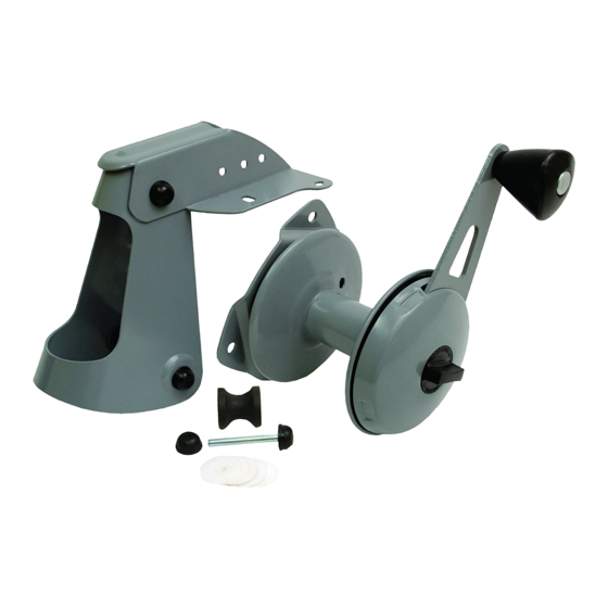
CONTENTS
• (1) quantity - Anchor Mount / Rope
Guide Assembly
• (1) quantity - Anchor Rope Reel
Assembly
• (1) quantity - Anchor Mount Rear
Pulley
• (1) quantity - Rear Pulley Axle
• (2) quantity - Push Nuts
• (6) quantity - Nylon Washers
• (1) quantity - Instruction Sheet
MATERIALS INCLUDED
Please Note: The Attwood Anchor
Lift System comes complete with the components listed
above. Due to the variety of watercraft and materials used
in the construction of boats today, Attwood has not included
mounting hardware such as bolts, screws, nuts, line guides
or pulleys. These are boat specifi c and must be supplied by
the consumer to meet their particular application and craft
specifi cations.
ANCHOR LIFT SYSTEM
MOUNTING INSTRUCTIONS:
It's always a good idea to enlist the help of second person during the installation
process to help in locating, holding and marking the assemblies for installation.
ANCHOR MOUNT / ROPE GUIDE INSTALLATION:
1. Determine a suitable location for the installation of the Anchor Mount / Rope Guide
Assembly and Anchor Rope Reel Assembly. Make sure that these locations have
enough support for the loads and space to properly mount and use the product with
clearances for the anchor rope to move freely during use.
For watercraft with decks or no opening in the bow plate, a 3/4 inch hole may be
necessary to be drilled directly beneath the rear roller of the Anchor Mount / Rope
Guide to provide proper routing of the anchor rope for your application.
Attwood recommends the use of swivel pulleys and guides to help route the rope to
properly utilize the Anchor Lift System by keeping the rope clear of obstructions and
to avoid undue chaffi ng and wear on the rope and the system. These are not supplied
but can be found at a marine dealer or online.
2. Once you have decided on the location for the Anchor Mount / Rope Guide place the
mount in position and mark, then drill the (4) holes to match the base mounting
hole positions.
3. If a ¾ inch clearance hole is required below the Anchor Mount / Rope Guide (see
fi gure A) now is the time to add it. Position the mount in place and mark the center
of the rear roller along it's rear edge. Then, using this mark, drill a ¾ inch clearance
hole for the rope to pass through.
4. Attach the Anchor Mount / Rope Guide by using ¼ inch bolts or screws (depending
on your boats specifi c construction and requirements), making sure all fasteners are
secure and tight.
# 69503 Rev B
Figure A
ANCHOR ROPE REEL INSTALLATION:
1. Place the Rope Reel in position and mark, and then drill, the (3) holes to match the
reel's mounting hole positions.
IMPORTANT: Make sure there is suffi cient clearance for the reel to operate freely
and there is no interference with oar locks, oars during use or motor and/or
steering components.
2. Install the ¼ inch bolts using the nylon washers supplied, one on each side of
the hull to provide a water resistant installation. Depending on your watercraft's
construction you may want to use a quality marine sealant to provide additional
watertight protection from water intrusion. Once all fasteners are in place verify that
all fasteners are secure and tight.
Figure B
ANCHOR ROPE ROUTING AND INSTALLATION:
1. The Attwood Anchor Lift System uses 3/16" diameter anchor rope up to 100 foot
capacity. Insert one end of the rope through the hole from the spool side. Tie a knot
in the end of the rope making sure that it is as tight as possible and trim off excess to
avoid rubbing and interference against the base when the reel is in operation.
2. Add slight tension to the line and slowly wind the rope onto the reel in a clockwise
direction. Having slight tension on the line keeps it from binding or becoming tangled
during the winding process and provides for much easier anchor release.
3. Once you have the anchor line wound on to the rope reel route the rope along the
side of the boat, determine if you will need rope guides or swivel pulleys, note the
placement of the guides, and install them following all of the Warnings and Cautions.
(Attwood recommends the use of swivel pulleys and guides to help route the rope to
properly utilize the Anchor Lift System by keeping the rope clear of obstructions and
to avoid undue chaffi ng and wear on the rope and the system. These are not supplied
but can be found at your local marine dealer or online at one of the many marine
retailers.)
4. Finalize the routing of the anchor line through the Anchor Mount / Rope Guide
Assembly, attach your anchor, and take up the slack in the line.
5. Verify the routing of the line making sure there is no chaffi ng or interference
between; the line, pulleys, guides and the watercraft.
Figure C
ATTWOOD ANCHOR LIFT SYSTEM OPERATION:
1. To actuate the release of the anchor simply turn the release knob in a CLOCKWISE
direction. The anchor will drop until you turn or release the knob back to original
starting position.
3/4 in. diameter
clearance hole
Leave ample clearance for
unobstructed operation
Advertisement

Related Manuals for Attwood 13710-4

Summary of Contents for Attwood 13710-4
- Page 1 ANCHOR ROPE ROUTING AND INSTALLATION: • (1) quantity - Rear Pulley Axle 1. The Attwood Anchor Lift System uses 3/16” diameter anchor rope up to 100 foot • (2) quantity - Push Nuts capacity. Insert one end of the rope through the hole from the spool side. Tie a knot •...
- Page 2 The rope reel release knob and the lift handle only operate in a clockwise direction. Operating these in a counter clockwise direction may cause damage. ATTWOOD ANCHOR LIFT SYSTEM CARE: 1. The Anchor Lift System comes completely lubricated from the factory with waterproof grease;...