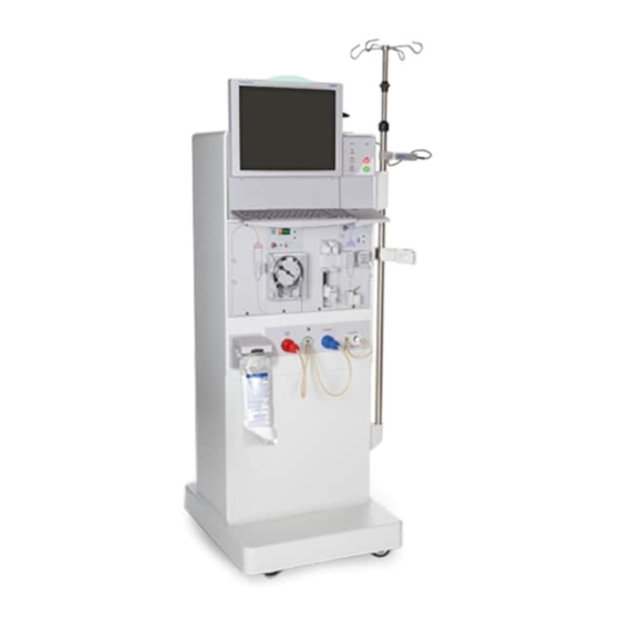
Fresenius Medical Care 2008T Calibration Procedure
Hemodialysis system
Hide thumbs
Also See for 2008T:
- Troubleshooting manual (769 pages) ,
- Operator's manual (370 pages) ,
- Quick start manual (20 pages)
Table of Contents
Advertisement
Advertisement
Table of Contents

Related Manuals for Fresenius Medical Care 2008T


Summary of Contents for Fresenius Medical Care 2008T
- Page 1 2008T HEMODIALYSIS SYSTEM CALIBRATION PROCEDURES Part Number 508032 Rev. H...
- Page 2 FRESENIUS MEDICAL CARE NORTH AMERICA 800-227-2572 Fresenius Medical Care North America 920 Winter St. Waltham, MA 02451 Manufactured by: Fresenius USA, Inc. 4040 Nelson Avenue Concord, CA 94520 REGIONAL EQUIPMENT SPECIALIST: ___________________________________...
- Page 3 2008T HEMODIALYSIS SYSTEM CALIBRATION PROCEDURES Part Number 508032 Rev. H http://www.fmcna.com Copyright 2008 – 2019 Fresenius Medical Care, All Rights Reserved Page i 2008T Calibration Procedures P/N 508032 Rev. H...
- Page 4 2008T Technician’s Manual, P/N 490130. Contact Fresenius Medical Care Technical Support for applicable Field Service Bulletins. The spare parts manual for the model 2008T and other information may be found on our web site at www.fmcna.com Indications for Use: The 2008T hemodialysis machine is indicated for acute and chronic dialysis therapy in a healthcare facility.
-
Page 5: Table Of Contents
2.4.4 VENOUS PUMP RATE ........................ 64 3.0 CALIBRATION PROCEDURES NOT PERFORMED IN SERVICE MODE ....65 3.1 INLET WATER PRESSURE REGULATOR CALIBRATION ........... 65 3.2 LEVEL DETECTOR CALIBRATION ..................67 3.3 BLOOD PUMP CALIBRATION ....................69 Page iii 2008T Calibration Procedures P/N 508032 Rev. H... - Page 6 Warning! Only Original Equipment Manufacturer (OEM) Fresenius Medical Care parts should be used in the repair or upgrade of the Fresenius Medical Care 2008T Hemodialysis System. Although, parts may look similar to parts in various vendor catalogs or brick and mortar stores the 2008T Hemodialysis System uses parts that have been specified and tested in accordance to ANSI/AAMI/ISO guidelines.
-
Page 7: Introduction
This information is stored on the functional board. Therefore, if the functional board and EEPROM are swapped out together when troubleshooting a calibration or machine problem, the machine must be rinsed prior to releasing it back into service. Page 1 2008T Calibration Procedures P/N 508032 Rev. H... -
Page 8: Test Equipment And Supplies Needed
• Stopwatch with a resolution to 0.01 second and an accuracy of 0.01% or better. • Buret, 25ml capacity with 0.1ml graduations (part number 290104). • Graduated cylinder: 100ml capacity with a tolerance of 0.60ml at 100ml or better. Page 2 2008T Calibration Procedures P/N 508032 Rev. H... -
Page 9: Operating Modes
1 mmHg at pressures up to 335 mmHg. OPERATING MODES The following calibration procedures contain instructions to place the 2008T into Dialysis Mode and Service Mode. To place the machine in Service Mode, turn the machine power On and wait for the message Press CONFIRM for Service Mode to appear. - Page 10 OPERATOR ERROR will appear on the display screen. The data stored in the EEPROM will not be changed if this message appears. Refer to Section 1.3 on the use of screen buttons. Page 4 2008T Calibration Procedures P/N 508032 Rev. H...
- Page 11 CONNECTOR #44 PRESSURE RELIEF VALVE (78) UF PUMP ADJUSTMENT FLOW PUMP BYPASS RELIEF VALVE (65) VALVE DEAERATION PUMP BYPASS VALVE FLOW PUMP OUTLET DEAERATION PUMP INLET Figure 1 - 2008T Rear View Page 5 2008T Calibration Procedures P/N 508032 Rev. H...
-
Page 12: Front Panel Controls
([CONFIRM] and [Escape] keys are located here) Figure 2 - 2008T Front Panel Throughout the calibration procedures, whenever a key is to be pressed, the appropriate key name is surrounded by square brackets as in the following example: Press the [CONFIRM] key and the screen will change. - Page 13 Use of the touch screen in Dialysis Mode is limited to Functional board software version 2.30 or greater or by having the touch screen activated in Functional board software version 2.13 using a special feature chip. Page 7 2008T Calibration Procedures P/N 508032 Rev. H...
-
Page 14: Measuring Fluid Volumes
• Surface tension causes the fluid to curve into a meniscus (see Figure 3). Measure the volume at the bottom of the meniscus curve as shown. BOTTOM OF THE MENISCUS CURVE Figure 3 - Meniscus Curve Page 8 2008T Calibration Procedures P/N 508032 Rev. H... -
Page 15: Calibrate If Replaced
Use of the touch screen in Dialysis Mode is limited to Functional board software version 2.30 or greater or by having the touch screen activated in Functional board software version 2.13 using a special feature chip. Page 9 2008T Calibration Procedures P/N 508032 Rev. H... -
Page 16: Service Mode Calibrations
There are a total of three dots that will appear. Touch each asterisk as they appear. When the calibration is complete, the screen will prompt you to power the machine off. Page 10 2008T Calibration Procedures P/N 508032 Rev. H... -
Page 17: Hydraulic Calibration Procedures
• Deaeration Pressure • Flow Pressure • Balance Chamber • Acid Pump Volume • Bicarbonate Pump Volume • UF Pump Volume Refer to Section 1.3 on the use of screen buttons. Page 11 2008T Calibration Procedures P/N 508032 Rev. H... -
Page 18: Deaeration And Loading Pressure Calibration
Connect a gauge equipped with a yellow connector into the red ACETATE/ACID port. Press the [CONFIRM] key. The deaeration pump will start and the screen will change. Refer to Section 1.3 on the use of screen buttons. Page 12 2008T Calibration Procedures P/N 508032 Rev. H... - Page 19 -24.0 1000 -23.0 2000 -22.0 3000 -21.0 4000 -20.0 5000 -19.0 6000 -18.5 7000 -17.5 8000 -16.9 9000 -16.2 10000 -15.5 Refer to Section 1.3 on the use of screen buttons. Page 13 2008T Calibration Procedures P/N 508032 Rev. H...
- Page 20 • If the machine is equipped with the bibag system, proceed to the next section in order to verify the bibag conductivity cell calibration. Page 14 2008T Calibration Procedures P/N 508032 Rev. H...
- Page 21 10. If the machine is in service mode, power off the machine. 11. Power on the machine and wait for the Select Program screen. 12. Set up the machine with a bibag disposable as described in the 2008T Hemodialysis Machine bibag System Operator’s Instructions (P/N 508213).
- Page 22 Once the bicarbonate conductivity cell is complete, verify the Bic Mon Cond and loading pressure are within acceptable ranges. If both are within range, the calibration is complete. Remove the gauges. Page 16 2008T Calibration Procedures P/N 508032 Rev. H...
-
Page 23: Flow Pressure Calibration
Press the [CONFIRM] key to complete the calibration and return to the Calibrate Hydraulics screen. Remove the gauge from the flow pump output. Refer to Section 1.3 on the use of screen buttons. Page 17 2008T Calibration Procedures P/N 508032 Rev. H... -
Page 24: Balance Chamber Volume Calibration
This bar is showing an approximate 15- second countdown before the contents of the balance chambers are dispensed from the drain port with two pulses of fluid. Refer to Section 1.3 on the use of screen buttons. Page 18 2008T Calibration Procedures P/N 508032 Rev. H... - Page 25 Replace the drain hose on the drain port. Press the [CONFIRM] key to complete the calibration and return to the Calibrate Hydraulics screen. Refer to Section 1.3 on the use of screen buttons. Page 19 2008T Calibration Procedures P/N 508032 Rev. H...
-
Page 26: Acid (Concentrate) Pump Volume Calibration
Press the [CONFIRM] key. The acid pump will stroke and the screen will change. Wait until the Target value reaches zero. Refer to Section 1.3 on the use of screen buttons. Page 20 2008T Calibration Procedures P/N 508032 Rev. H... - Page 27 15. Press the [CONFIRM] key again to save the data. The screen will change. Press the [CONFIRM] key one more time to complete the calibration and return to the Calibrate Hydraulics screen. Refer to Section 1.3 on the use of screen buttons. Page 21 2008T Calibration Procedures P/N 508032 Rev. H...
-
Page 28: Bicarbonate Pump Volume Calibration
Press the [CONFIRM] key. The bicarbonate pump will stroke and the screen will change. Wait until the Target value reaches zero. Refer to Section 1.3 on the use of screen buttons. Page 22 2008T Calibration Procedures P/N 508032 Rev. H... - Page 29 15. Press the [CONFIRM] key again to save the data. The screen will change. Press the [CONFIRM] key one more time to complete the calibration and return to the Calibrate Hydraulics screen. Refer to Section 1.3 on the use of screen buttons. Page 23 2008T Calibration Procedures P/N 508032 Rev. H...
-
Page 30: Uf Pump Volume Calibration
[Prime] key again to stop the pump. Add or remove fluid from the buret so the meniscus is exactly on the 25ml mark (see Figure 4). Refer to Section 1.3 on the use of screen buttons. Page 24 2008T Calibration Procedures P/N 508032 Rev. H... - Page 31 Press the [CONFIRM] key again. The UF pump will stroke and the screen will change. Wait until the Target value reaches zero. Refer to Section 1.3 on the use of screen buttons. Page 25 2008T Calibration Procedures P/N 508032 Rev. H...
- Page 32 0.90 and 1.10 on the scale after 24 strokes of the UF pump. Replace the plastic cap on the UF pump adjustment. Press the [CONFIRM] key to complete the calibration and return to the Calibrate Hydraulics screen. Page 26 2008T Calibration Procedures P/N 508032 Rev. H...
-
Page 33: Sensor Calibration Procedures
• Venous Pressure • Dialysate Pressure • Temperature Sensor • Post Temperature Sensor • Temperature Control • Blood Leak Detector • Conductivity Cells Refer to Section 1.3 on the use of screen buttons. Page 27 2008T Calibration Procedures P/N 508032 Rev. H... -
Page 34: Arterial Pressure Calibration
ON. LP955 switch Description ON for future use OFF for use on the 2008T ON for Pre-Pump Arterial Pressure OFF for Post-Pump Arterial Pressure Not Used ON for blood pump stop alarm after 30 sec... - Page 35 • For prepump, DIP switch 2 must be in the ON position • For postpump, DIP switch 2 must be in the OFF position Power the 2008T machine ON and enter Service Mode. When the power up sequence is complete, the blood pump display will be alternating...
- Page 36 Note: Depending on the HARDWARE OPTION set for the ART PUMP option, the above display may read POSTPUMP instead of PREPUMP. The bargraph scale will also be different (500 to –80mmHg). Refer to Section 1.3 on the use of screen buttons. Page 30 2008T Calibration Procedures P/N 508032 Rev. H...
- Page 37 ] keys on the blood pump to adjust the Arterial Pressure data box on the 2008T display to indicate 0 mmHg. Press the [CONFIRM] key and the 2008T display will change. Press the [Start/Stop] key on the blood pump and its display will change back to...
- Page 38 ] keys on the blood pump to adjust the Arterial Pressure data box on the 2008T display to indicate 200mmHg. • Press the [CONFIRM] key and the 2008T display will change. • Press the [Start/Stop] key on the blood pump and its display will change back to the alternating display: •...
- Page 39 Press the [CONFIRM] key to complete the calibration and return to the Calibrate Sensors screen. Power the machine OFF and move the blood pump Service Jumper into the Not in Service Mode position (see Figure 5). Page 33 2008T Calibration Procedures P/N 508032 Rev. H...
-
Page 40: Venous Pressure Calibration
Press the [CONFIRM] key and the screen will change. Attach a syringe and a calibrated pressure gauge to the P port using a T- fitting. Refer to Section 1.3 on the use of screen buttons. Page 34 2008T Calibration Procedures P/N 508032 Rev. H... - Page 41 400 MMHG SET (P4) ZERO SET (P3) LP450 Note: The type of potentiometer may vary in shape and size. Figure 6 - Venous Pressure Display Adjustments Page 35 2008T Calibration Procedures P/N 508032 Rev. H...
- Page 42 –90mmHg and that they are within 10mmHg of each other. Press the [CONFIRM] key to save the calibration. The screen will change. Press the [CONFIRM] key again to complete the calibration and return to the Calibrate Sensors screen. Page 36 2008T Calibration Procedures P/N 508032 Rev. H...
-
Page 43: Dialysate Pressure Calibration
#9 in the hydraulic flow path. Press the [CONFIRM] key and the screen will change. Refer to Section 1.3 on the use of screen buttons. Page 37 2008T Calibration Procedures P/N 508032 Rev. H... - Page 44 Press the Dialysate Flow On screen button and then press the [CONFIRM] key to start dialysate flow. Press the [CONFIRM] key to complete the calibration and return to the Calibrate Sensors screen. Page 38 2008T Calibration Procedures P/N 508032 Rev. H...
-
Page 45: Temperature Sensor Calibration
Remove the previous test connector and connect test connector 41 (5.117KΩ) into X3 (MON-NTC) connection on the distribution board. Press the [CONFIRM] key to save the data. The screen will change. Refer to Section 1.3 on the use of screen buttons. Page 39 2008T Calibration Procedures P/N 508032 Rev. H... - Page 46 Temperature data box. Press the [CONFIRM] key to complete the calibration and return to the Calibrate Sensors screen. Remove the test connector and replace the X3 (MON-NTC) connector on the distribution board. Page 40 2008T Calibration Procedures P/N 508032 Rev. H...
-
Page 47: Post Temperature Sensor Calibration
Wait for the Post-Temperature Reference data box to stabilize. Press the [CONFIRM] key to save the data. The screen will change. Refer to Section 1.3 on the use of screen buttons. Page 41 2008T Calibration Procedures P/N 508032 Rev. H... - Page 48 Temperature data box. Press the [CONFIRM] key to complete the calibration and return to the Calibrate Sensors screen. Remove the test connector and replace the X44 (NTC-POST) connector on the distribution board. Page 42 2008T Calibration Procedures P/N 508032 Rev. H...
-
Page 49: Temperature Control Calibration
Allow Slow Flow option enabled. Dialysis treatment times can increase with the Temp Comp option enabled. Refer to the 2008T Hemodialysis Machine Operator’s Manual (P/N 490122) for further details. Perform Method 1 section 2.3.6.1 if all the following apply: - Temp Comp option is disabled. -
Page 50: Temperature Control Calibration (Method 1)
From the Calibrate Sensors screen, select the Temp Control screen button. The screen will change to the following: Refer to Section 1.3 on the use of screen buttons. Page 44 2008T Calibration Procedures P/N 508032 Rev. H... - Page 51 Note: The TEMP DAC value does not take effect until the [CONFIRM] key is pressed and the TEMP DAC data button is light yellow. Refer to Section 1.3 on the use of screen buttons. Page 45 2008T Calibration Procedures P/N 508032 Rev. H...
- Page 52 Press the [CONFIRM] key to complete the calibration and return to the Calibrate Sensors screen. Refer to Section 1.3 on the use of screen buttons. Page 46 2008T Calibration Procedures P/N 508032 Rev. H...
-
Page 53: Temperature Control Calibration (Method 2)
From the Calibrate Sensors screen, select the Temp Control screen button. The screen will change to the following: Refer to Section 1.3 on the use of screen buttons. Page 47 2008T Calibration Procedures P/N 508032 Rev. H... - Page 54 Note: If the Stability counter drops below 70 during the 2-minute Timer, the 2 minutes will be reset and will wait for the Stability counter to be greater than 70 again. Refer to Section 1.3 on the use of screen buttons. Page 48 2008T Calibration Procedures P/N 508032 Rev. H...
- Page 55 Press the [CONFIRM] key to complete the calibration and return to the Calibrate Sensors screen. Refer to Section 1.3 on the use of screen buttons. Page 49 2008T Calibration Procedures P/N 508032 Rev. H...
-
Page 56: Blood Leak Calibration
Operator’s Manual before calibrating the blood leak detector. Press the [CONFIRM] key. The screen will change and the blood leak calibration will start. Refer to Section 1.3 on the use of screen buttons. Page 50 2008T Calibration Procedures P/N 508032 Rev. H... - Page 57 When it’s finished, the following calibration complete screen will be displayed: Press the [CONFIRM] key to save the data. The screen will change. Press the [CONFIRM] key again to complete the calibration and return to the Calibrate Sensors screen. Page 51 2008T Calibration Procedures P/N 508032 Rev. H...
-
Page 58: Conductivity Cells Calibration
Bicarb Cell (if bibag equipped) • Cond Conf Cell – This is the Independent Conductivity Cell (Functional board software version 2.71 or later) Refer to Section 1.3 on the use of screen buttons. Page 52 2008T Calibration Procedures P/N 508032 Rev. H... -
Page 59: Dialysate Cells Calibration
OPTIONS screen button. Press the [CONFIRM] key to select your concentrate and the screen will return to the CALIBRATE CONDUCTIVITY CELL(S) screen. Refer to Section 1.3 on the use of screen buttons. Page 53 2008T Calibration Procedures P/N 508032 Rev. H... - Page 60 Press the [CONFIRM] key to save the data. The screen will change. Disconnect the dialyzer and replace the dialysate lines in the shunt. 13. Press the [CONFIRM] key to complete the calibration and return to the Calibrate Sensors screen. Page 54 2008T Calibration Procedures P/N 508032 Rev. H...
-
Page 61: Bicarbonate Conductivity Cell Calibration
During the calibration process, the 90XL will communicate with the machine through the RS232 port. When the calibration process is complete, the screen will display Bicarb Cond Cell calibration is complete. Refer to Section 1.3 on the use of screen buttons. Page 55 2008T Calibration Procedures P/N 508032 Rev. H... -
Page 62: Conductivity Confirmation Cell Calibration
Connect the Dialysate Lines to the 90XL Conductivity/Temperature Module. Connect the acid connector to a container of acid and the bicarbonate connector to a container of sodium bicarbonate concentrate. Refer to Section 1.3 on the use of screen buttons. Page 56 2008T Calibration Procedures P/N 508032 Rev. H... - Page 63 90XL. case, the 90XL power cable can be plugged into this port. Any port is ok, if only the conductivity probe is connected to the 90XL. MESA SERIAL CABLE P/N 368402-10 Page 57 2008T Calibration Procedures P/N 508032 Rev. H...
-
Page 64: Maintenance Calibration Procedures
• Venous Pump Rate • Crit-Line Calibration (Functional board software version 2.61 or later) • Scheduler (Functional board software version 2.71 or later) Refer to Section 1.3 on the use of screen buttons. Page 58 2008T Calibration Procedures P/N 508032 Rev. H... -
Page 65: Set Time & Date
• When all of the data has been entered, press the [CONFIRM] key to return to the Calibrate Monitor or Maint. screen. Refer to Section 1.3 on the use of screen buttons. Page 59 2008T Calibration Procedures P/N 508032 Rev. H... -
Page 66: Voltage Detection Calibration
Set the 12 volt set value to the voltage shown on the digital voltmeter, then press the [CONFIRM] key. Press the [CONFIRM] key again and the screen will change. Refer to Section 1.3 on the use of screen buttons. Page 60 2008T Calibration Procedures P/N 508032 Rev. H... - Page 67 +12 VOLT TEST POINT ON JUMPER 1 SENSOR BOARD MONITOR CONTROL UNIT CARD CAGE FUNCTIONAL TOP VIEW BOARD GROUND (P31) Figure 7 - +12 Volt and Ground Test Points Page 61 2008T Calibration Procedures P/N 508032 Rev. H...
- Page 68 Calibrate Monitor screen. Disconnect the Digital Voltmeter and close the monitor unit. Press the [CONFIRM] key to complete the calibration and return to the Calibrate Monitor or Maint. screen. Page 62 2008T Calibration Procedures P/N 508032 Rev. H...
-
Page 69: Arterial Pump Rate
Press the [CONFIRM] key again to save data. Press the [CONFIRM] key again to complete the calibration and return to the Calibrate Monitor or Maint. screen. Refer to Section 1.3 on the use of screen buttons. Page 63 2008T Calibration Procedures P/N 508032 Rev. H... -
Page 70: Venous Pump Rate
Press the [CONFIRM] key again to save data. Press the [CONFIRM] key again to complete the calibration and return to the Calibrate Monitor or Maint. screen. Refer to Section 1.3 on the use of screen buttons. Page 64 2008T Calibration Procedures P/N 508032 Rev. H... -
Page 71: Calibration Procedures Not Performed In Service Mode
Dialysis mode and start the dialysate flow. The pressure gauge will cycle between two readings as water inlet valve opens and closes. Refer to Section 1.3 on the use of screen buttons. Page 65 2008T Calibration Procedures P/N 508032 Rev. H... - Page 72 10. Turn the treated water supply source On, turn the machine On and select Dialysis Mode. Start dialysate flow and inspect all hoses and connections for leaks. Refer to Section 1.3 on the use of screen buttons. Page 66 2008T Calibration Procedures P/N 508032 Rev. H...
-
Page 73: Level Detector Calibration
(see Figure 8) clockwise until the LED turns off. 11. Slowly turn channel 1 potentiometer counter-clockwise until the channel 1 LED switches on. Stop turning immediately, just past the point where the LED lights. Page 67 2008T Calibration Procedures P/N 508032 Rev. H... - Page 74 CHANNEL 1 potentiometer may vary in shape and size. CHANNEL 2 CHANNEL 1 LED LIGHTS FIRST CHANNEL 2 LED LIGHTS SECOND JUMPER POSITIONS NORMAL CALIBRATE Figure 8 - Level Detector Calibration Adjustments Page 68 2008T Calibration Procedures P/N 508032 Rev. H...
-
Page 75: Blood Pump Calibration
BLOOD PUMP CALIBRATION The speed control circuit on a 2008T blood pump consists of a feedback circuit that monitors the motor speed and automatically adjusts to compensate for any speed fluctuations. There are no adjustments or calibrations on this circuit. - Page 76 NOTES: ____________________________________________________________________________________ ____________________________________________________________________________________ ____________________________________________________________________________________ ____________________________________________________________________________________ ____________________________________________________________________________________ ____________________________________________________________________________________ ____________________________________________________________________________________ ____________________________________________________________________________________ ____________________________________________________________________________________ ____________________________________________________________________________________ ____________________________________________________________________________________ ____________________________________________________________________________________ ____________________________________________________________________________________ ____________________________________________________________________________________ ____________________________________________________________________________________ ____________________________________________________________________________________ ____________________________________________________________________________________ ____________________________________________________________________________________ ____________________________________________________________________________________ ____________________________________________________________________________________ ____________________________________________________________________________________ ____________________________________________________________________________________ ______________________________________________________________________________ ______________________________________________________________________________ Page 70 2008T Calibration Procedures P/N 508032 Rev. H...
- Page 77 COMMON CONVERSIONS PRESSURE 1 Bar 29.53 inHg 1 inHg 25.4 mmHg 1 Psi 51.72 mmHg VOLUME 1 FLUID OUNCE 29.6 MILLILITERS 1 U.S QUART 0.946 LITERS 1 U.S. GALLON 3.8 LITERS 0.034 FLUID OUNCES 1 MILLILITER 1.057 QUARTS 1 LITER 0.26 U.S.
- Page 78 Fresenius Medical Care North America Manufactured by: Fresenius USA, Inc. 4040 Nelson Avenue Concord, CA 94520 800 227-2572 http://www.fmcna.com...