Table of Contents
Advertisement
STUDER INNOTEC
User and installer Manual
Combi Inverter, Battery charger
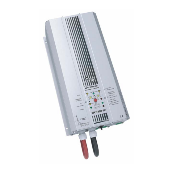
XP-COMPACT XPC 1400-12
XP-COMPACT XPC 2200-24
XP-COMPACT XPC 2200-48
STUDER INNOTEC
Rue des Casernes 57
CH-1950 SION
User manual
and Transfersystem
Remote control
Temperature sensor
Solar charge controller
AC cable cover
IP-23 top cover
TEL: ++41 (0)27 205 60 80
FAX: ++41 (0)27 205 60 88
EMAIL : info@studer-innotec.com
XP-COMPACT V5.1 E
RCC-01
CT-35
XPCxxxx-S
CFC-01
C-IP23
XP-COMPACT
Advertisement
Table of Contents

Related Manuals for Studer XPC 1400-12


Summary of Contents for Studer XPC 1400-12
- Page 1 STUDER INNOTEC User and installer Manual Combi Inverter, Battery charger and Transfersystem XP-COMPACT XPC 1400-12 XP-COMPACT XPC 2200-24 XP-COMPACT XPC 2200-48 Remote control Temperature sensor Solar charge controller AC cable cover STUDER INNOTEC Rue des Casernes 57 CH-1950 SION User manual...
-
Page 2: Table Of Contents
STUDER Innotec Summary General Information ...3 PERATING INSTRUCTIONS UALITY AND ARRANTY ARRANTY ISCLAIMER ...3 IABILITY ISCLAIMER ...4 RECAUTIONS ...4 PECIAL RECAUTIONS Introduction...5 ...5 RINCIPLE SCHEMATIC ESCRIPTION OF MAIN FUNCTIONS 2.2.1 The inverter...5 2.2.2 The transfer system ...5 2.2.3 The battery charger...6 2.2.4... - Page 3 STUDER Innotec 4.8.3 Delayed mode of the Transfer System ...15 OLAR CHARGE CONTROLLER 4.10 ULTIFUNCTIONAL 4.11 EMPERATURE SENSOR The Remote Control ...16 EMOTE CONTROL PLUG ...16 OWER MONITOR :...17 ATTERY ONDITION ...17 AULT INDICATOR 5.4.1 Overtemp. (10) ...17 5.4.2 Overload (11)...17 5.4.3...
-
Page 4: General Information
Respecting this manual, servicing and method of installation, functioning, application and mainte- nance of the appliance can not be controlled or supervised by STUDER INNOTEC. Hence we do not accept any liability and responsibility for damages, loses and costs which result through the use of this appliance or which result through incorrect installation, incorrect operation or wrong application and maintenance or which by some other means maybe connected together to these. -
Page 5: Precautions
The whole installation connected with the XP-COMPACT must comply with the respective valid codes and ordinances. Persons without the written authorization from STUDER INNOTEC are strictly forbidden to carry out any changes or repairs on the appliances. For authorized changes only original parts are to be used. -
Page 6: Introduction
STUDER Innotec 2 Introduction The XP-COMPACT is a sine wave inverter with integrated battery charger and solar charge con- troller with many additional functions, it has been developed to be used as stand-alone (no grid feeding) AC provider, or as continuous / break-free current supply provider (UPS). -
Page 7: The Battery Charger
STUDER Innotec 2.2.3 The battery charger The built-in battery charger is so designed that it can charge the battery quickly and fully. A micro- processor controlled, 3 to 4 Step charging process ensures the optimum charging of the batteries. The desired charging current can be set continuously from 0 to maximum, according with particular technical specification (chap.6). -
Page 8: Connection In Parallel And In Serie
STUDER Innotec 2.3.3 Connection in parallel and in serie 3 Mounting and installing 3.1 Installation place The location of the XP-COMPACT must be chosen by the following criteria: - Protection against unauthorized handling - Dry dust free room, no condensation - Never install directly over the battery and never in a cabinet together with the batteries - Keep ventilation holes free. -
Page 9: Protection Cover For The Terminals Connections
STUDER Innotec Connecting must be done by qualified staff. Material such as cable, connectors and distribution boxes, fuses etc. used in the installation must comply with the respective valid low-voltage installa- tion rules and regulations. 3.4.2 Protection cover for the terminals con-... -
Page 10: Cabling/Wiring
Caution: With a wrong battery voltage the XP-COMPACT can be destroyed. (For example: connecting a XPC 1400-12 to a 48V-Battery). Nevertheless if the XP-COMPACT had been connected with reverse polarity, it is highly probable that the fuse inside the casing is broken. -
Page 11: Connection To Auxiliary Contact
STUDER Innotec XPC 1400-12 17-25V/30A, XPC 2200-24 34 – 45V/30A, XPC 2200-48 68 – 90V/20A. 3.6.6 Connection to Auxiliary Contact On these three terminals is a potential free change-over contact. The maximal permitted current and voltage for this is 16A/250Vac. The LED 5 “Contact active” shows the position of them: alight means active and off means non-active. -
Page 12: Display And Control Parameters On Remote Control Panel (Optional)
STUDER Innotec 4.2 Display and control parameters on remote control panel (optional) INVERTER - CHARGER AC IN CHARGER SOLAR CHARGE EQUALIZE Program Contact active Contact manual AUXILIARY CONTACT (Program) RCC-01 4.3 Light Emitting Diodes (LED) Marking LED lit AC IN... -
Page 13: Push Buttons
STUDER Innotec Batt. Low/High Battery voltage is too low XP-COMPACT is turned off. Turn- ing it back on is only possible manually. Battery Charger and/or Solar Charge Controller are doing an equalization cycle 15-18* Charge condition of Battery CURRENT Display the value of the output power in % of Pnom (in Inverter Mode) MONITOR and the charge current in Amps. -
Page 14: Overheating (Over Temp)
STUDER Innotec 4.6.3 Overheating (Over Temp) If the Inverter has been overloaded for a long time or it has been working in a too high surrounding temperatures, it will switch off. The LED 13 „OFF“ blinks. After cooling down, the inverter switches back on automatically. -
Page 15: Equalization Charging
STUDER Innotec 4.7.2 Equalization charging Before you program the XP-COMPACT for Equalization-charge you must check with your supplier that the batteries are suitable for this process. Equalization is recommended for the lead-acid batteries in order to mix well the electrolyte fluid and to clean the lead plates. -
Page 16: Set The Transfer Voltage Threshold
SOLAR +/-. The in-built controller is a „Shunt con- troller“ for the maximum input current of 30A for XPC 1400-12 and XPC 2200-24 and 20A for XPC 2200-48. The operating voltage of Solar panels to be connected must match the actual operating voltage of the XP-COMPACT and never exceeds the max. -
Page 17: The Multifunctional Contact
STUDER Innotec 4.10 The Multifunctional Contact In the XP-COMPACT there is a built-in power relay. The potential-free change-over contact (NO – NC) of this power relay is connected to the screw terminal AUX CONTACT. Maximum Contact load: 230Vac /12Vdc/24Vdc/16Amp The contact is activated when the XP-COMPACT is halted or by a fault condition, or by a normal manual stop done by pushing push-button 19. -
Page 18: Battery Condition
STUDER Innotec 5.3 Battery Condition Built-in microprocessor calculates the actual state of charge of the battery and displays it on LED 15 – 18. The LED 14 is lit when the system is carrying out a charge cycle with equalization. -
Page 19: Standard Setting
STUDER Innotec 6.1 Standard setting The XP-COMPACT (except for 60Hz versions) is equipped with a Flash processor fitted out with EEPROM Memory, which means that even when it is disconnected from the battery, the parame- ters that were programmed for the application remain after a new connection to the battery. -
Page 20: Program The Auxiliary Contact
STUDER Innotec These four red LED show the function set: Low voltage LED 13 Float charge LED 12 Absorption (End of charge) LED11 Equalization LED 10 Absorptions Time LED 10/11/12/13 With the Push Button 19 (Change status) set the desired parameter (voltage or the time) to modify (LED 14/15/16/17/18). -
Page 21: Example
STUDER Innotec 6.4.3 Example 6.4.3.1 Auxiliary Contact as generator starter When in the programming of the Auxiliary Contact, the Battery Capacity (LED 15-18) is used as a condition, then you must take note of the following requirements. If you have to start an emergency back-up supply with a battery having a certain residual capacity, then two battery levels must be programmed. -
Page 22: Maintenance
Hereby we state that the products described in this user manual meet the following standards: EN 61000-6-1, EN 61000-6-3, EN 55014, EN 55022, EN 61000-3-2, Dir. 89/336/EEC, LVD 73/23/EEC, EN 50091-2, EN 60950-1. CH-1950 Sion, the 1 of January 2003 STUDER INNOTEC (R.Studer) User manual XP-COMPACT V5.1 E... -
Page 23: Technical Data
Remote control (112 x 138 x 25mm / 20 m cable) IP-23 top cover AC cable cover Battery temperature sensor (58 x 51.5 x 22mm / 3 m cable) Data may change without any notice User manual XPC 1400-12 XPC 2200-24 9.5 – 16V 19 - 32V 1100VA 1600VA 1400VA...