
Related Manuals for ABB AC500-eCo Series


Summary of Contents for ABB AC500-eCo Series
- Page 1 Hardware Introduction AC500-eCo ________________________________________________________________________________________________________ - 1 - AC500-eCo Hardware Introduction...
- Page 2 About this Heft: The AC500-eCo family is a comfortable and small control family with fully-upward-compatibility for the economic or stand-alone solution. This manual is just a short introduction to the AC500-eCo system. For further information please refer to the AC500 system manual. Chapter 1 Introduction: gives a brief overview of the AC500 System, and describes the system structures.
-
Page 3: Table Of Contents
Table of Contents About this Heft: ......................- 2 - 1. Introduction ......................- 4 - 1.1 AC500 System Overview....................- 4 - 1.2 New Product of AC500 PLC Family ................- 7 - 2. AC500-eCo Hardware Descriptions ................- 8 - 2.1 CPU Overview ........................- 8 - 2.1.1 CPU components ........................- 8 - 2.1.2 CPU Assortments........................- 9 - 2.1.3 The CPU onboard I/Os ......................- 9 -... -
Page 4: Introduction
This chapter describes the AC500 PLC’s family and shows the system structures. 1.1 AC500 System Overview Figure 1 AC500 PLC Overview This Figure shows the ABB AC500 PLC family, different CPU Type with different performance and memory. The principle AC500 PLC system structure is shown in the following figure:... - Page 5 Following table shows the AC500 CPUs with different features. Details/Type: PM554 PM564 PM571 PM581 PM582 PM590 PM591 24 V DC 24 V DC 24 V DC 24 V DC 24 V DC 24 V DC 24 V DC Supply voltage(DC) 100- 100- 100-...
- Page 6 Overview of the S500 I/O Module AI523 AX521 AX522 AO523 AI561 AO561 AX561 AI562 AI563 Number of Channels per Module analoge Inputs analoge Outputs Inputs, single configurable -2.5V…+2.5V -5V…+5V 0…5V 0…10V 0…20mA 4…20mA Outputs, single configurable -10V…+10V 0…20mA 4…20mA Inputs Thermo couple S500-eCo ________________________________________________________________________________________________________...
-
Page 7: New Product Of Ac500 Plc Family
1.2 New Product of AC500 PLC Family The AC500 CPUs type PM554, PM564 and the S500-eCo I/O modules are the new products of the AC500 PLC family. The CPUs: The new CPUs (PM554, PM564) are the enter-point of the AC500 CPUs of different performance classes, as the compact and cost effective controller for small applications;... -
Page 8: Ac500-Eco Hardware Descriptions
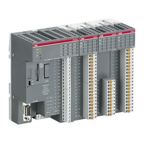
2. AC500-eCo Hardware Descriptions 2.1 CPU Overview The CPU PM554 and PM564 is the central unit of the AC500 system with the onboard digital/analog inputs and outputs. The CPUs can be powered by 24V DC or 100-240V AC depending on different variant. The different between two CPU types is the onboard I/O type. -
Page 9: Cpu Assortments
2.1.2 CPU Assortments AC500 CPUs PM554 and PM564 have the following five Assortments: Power Digital Digital Analog Analog Program Cycle time for 100 Other CPU types Supply Inputs Outputs Inputs* Output Memory instructions Interface 24V DC Serial Binary: Transistor 0.3 ms interfaces PM554-T COM1 and... -
Page 10: Communication Interfaces
2.1.4 Communication Interfaces COM1 The serial interface COM1 is connected to a 9-pin SUB-D Connector. COM1 is a RS-485 serial interface and can be used for Online access (RS-485 programming interface for PC/Control Builder) Modbus RTU as master or slave ASCII serial protocols CS31 Master RTC + Battery, SD-card on SD Card Adapter (Option) -
Page 11: Mode Selection Switch Run/Stop
2.1.6 Mode Selection Switch RUN/STOP AC500 CPUs PM554 and PM564 have RUN/STOP mode selection switch. User application programs can only be implemented when RUN/STOP switch is set to RUN mode. If RUN/STOP switch is set to STOP mode, the user application programs will be stopped. It must be use the screwdriver to change swatch’s condition. -
Page 12: S500-Eco I/O Modules Overview
2.2 S500-eCo I/O Modules Overview The S500-eCo I/O modules are with compact housing for DIN-Rail or wall mounting. It has the same height and depth as the standard S500 modules and can be used or mixed with the standard S500 I/Os on all AC500 CPUs. 2.2.1 I/O Unit components 1. -
Page 13: Hardware Installation And Wiring
Analog I/Os overview AI561 AO561 AX561 AI562 AI563 Number of Channels per Module Analog Inputs Analog Outputs Inputs, single configurable as -2.5V…+2.5V -5V…+5V 0…5V 0…10V 0…20mA 4…20mA Outputs, single configurable as -10V…+10V 0…20mA 4…20mA Inputs Thermo Couple 3. Hardware Installation and Wiring This Chapter provides general precautions for using the AC500 and related devices. -
Page 14: Hardware Mounting
3.1 Hardware Mounting During panel or DIN rail mounting of all devices, be sure that all debris (metal chips, wire ATTENTION strands, etc.) is kept from falling into the controller. Debris that falls into the controller could cause damage while the controller is energized. 3.1.1 DIN Rail Mounting/ re-Mounting Mounting on DIN rail Step 1: Install the... - Page 15 You can use the following components to add additional I/Os: If you want … … use the following component(s): DI561(8DI),DI562(16DI),DO561(8DO),DX561(8 • to connect a digital 24 VDC sensor or DI-T,8DO-T),DX571(8DI-R,8DO-R),DC561(16DI actuator to the CPU … /DO-T),DO571(8DO-R) • o connect a 100-240 VAC sensor or actuator DI571(8DI),DO572(8DO-Triac),DO571(8DO-R) to the CPU ...
-
Page 16: Wall Mounting
3.1.2 Wall Mounting If the CPU or I/O module should be mounted with screws, Wall Mounting Accessories TA566 must be inserted at the rear side first. 1. The Wall Mounting Accessories TA566 is snapped on the rear side of the CPU or the I/O modules. -
Page 17: Wiring
3.2 Wiring Wiring cautions • Do not lay I/O signal cables next to power cables or allow them to share the same trunk duct. Low voltage cables should be reliably separated or insulated with regard to high voltage cabling. • Where I/O signal lines are used over an extended distance consideration for voltage drop and noise interference should be made. -
Page 18: Terminal Block
3.2.2 Terminal Block The terminal block has to be embedded on the fixed terminals and only after that the cable can be connected during the terminal block. Depending on how many poles on the terminal block, there were three kinds: - 5 poles for the power supply;... -
Page 19: Appendix
4. Appendix 4.1 Technical Data PM554 PM564 Table 0, Details/Type PM554-T, PM554-R PM554-R-AC PM564-T, PM564-R Supply voltage 24 V DC 24V DC or 100-240V AC 24 V DC Program memory 128 KB 128 KB 128 KB Integrated data memory[KB] 10 KB 10 KB 10 KB Memory card adapter (option) - Page 20 number of timers unlimited unlimited unlimited number of counters unlimited unlimited unlimited Programming languages Function Block Diagram(FBS) Instruction List(IL) Ladder Diagram(LD) Structured Text(ST) Sequential Function Chart(SFC) Continuous Function Chart(CFC) Approvals CE, cUL E /A-Module, digital I/O Tabelle 1: digitale E/A DI561 DI562 DI571...
- Page 21 Eingangsspannung±5 V < 1 mA >1 mA < 1 mA < 1 mA < 1 mA - - - - bei Eingangsspannung > 2.5 mA > 2.5 mA > 2.5 mA > 2.5 mA > 2.5 mA - - - -...
- Page 22 max. 11 Hz max. 11 Hz - bei Lampenlast bei max. 5 max. 1 Hz max. 10 Hz bei max. 5 max. 1 Hz - - - - Kurzschluss- / - - - Überlastfestigkeit Überlastmeldung (I > 0,7 - - -...
- Page 23 zwischen den - - - - - - - - - Eingangs-Kanälen zwischen den - - - - - - - - - Ausgangs-Kanälen Intern über Erweiterung Intern über Spannungsversodergun sbus-Schnit Rückwandb g des Moduls tstelle (I/O-Bus) Über AC500-CP Über Feldbus-Anschluss U bzw.
- Page 24 Pt100, -50 ° C...+70 ° C (3-Draht), belegt 2 AI 2 / 2 - - - - Pt1000, -50 ° C...+400 ° C (2-Draht) 2 / 2 - - - - Pt1000, -50 ° C...+400 ° C (3-Draht), belegt 2 AI 2 / 2 -...
-
Page 25: Order Number
4.2 Order Number CPUs Cycle time in ms 1000 Onboard Program instructions I/Os Type Power supply Order Number memory Bit/Word/Float. Point DI/DO/AI/AO PM554-T 128 KB 0.3 / 0.3 / 6 8 / 6 / – / – 24 V DC 1TNE968900R0100 PM554-R 128 KB... -
Page 26: Guidelines Of Safety
This manual provides information for the installation and the usage of the ABB product AC500-ECO PLC. In no event will ABB be responsible or liable for indirect or consequential damages resulting from the use or application of this equipment. Solid state equipment has operational characteristics differing from those of electromechanical equipment. - Page 27 Identifies information about practices or circumstances that can cause an WARNING explosion in a hazardous environment, which may lead to personal injury or death, property damage, or economic loss. Identifies information that is critical for successful application and IMPORTANT understanding of the product. Identifies information about practices or circumstances that can lead to ATTENTION personal injury or death, property damage, or economic loss.
- Page 28 "Used as directed" implies that the devices are installed, maintained and operated in accordance with appropriate ABB manuals & documents. No liability is assumed for the direct or indirect consequences of the improper use, improper application or inadequate maintenance of these devices.
- Page 29 Risk reduction instructions Protect the devices from dampness, dirt and damage during transport, storage and operation! Do not operate devices outside of the specified, technical data! Trouble-free functioning cannot be guaranteed outside of the specified data. Operate the control system only in an enclosed housing (switch cabinet)! Due to their construction (degree of protection IP 20 according to EN 60529) and their connection technology, the devices are suitable only for operation in enclosed housings (switch cabinets).
- Page 30 The extent of resulting errors must be kept to a minimum. Use only ABB approved lithium battery modules! At the end of the battery’s lifetime, always replace it only with a genuine battery module.
-
Page 31: Services And Training
4.4 Services and Training 4.4.1 Technical Support Center ABB operates a Technical Support Center to assist with even the most difficult of problems. Consultation by phone (Helpline) Failure analysis and removal at the machine/installation In order to provide the customer with qualified assistance, customers are requested to provide the following: Provide all required application documentation and information. -
Page 32: Repair Services And Replacement Devices
If desired, we also offer seminars at the customer's facility. Please find detailed information in our seminar brochure. You can order this brochure from the address given above or from every ABB STOTZ-KONTAKT GmbH office or you can download it from our Internet website (PDF file, see the following link). -
Page 33: Bus System Overview
4.5 Bus System Overview Brief information about Ethernet Ethernet Ethernet operates with a data rate of 10 MBit/s and as Fast-Ethernet with 100 MBit/s. Ethernet utilizes the producer/consumer model. This means that every station possesses equal rights. While it is transmitting, all other stations listen in and accept the data directed to them. Bus access is regulated by the CSMA/CD procedure (Carrier-Sense Multiple-Access with Collision Detection), where each station may autonomously transmit when the bus is free. - Page 34 Brief Information about CS31 CS31 (Communication Serial, developed by ABB in 1989) for continuity and migration CS31 is a proprietary master/slave field bus. It is characterized by simple handling, easy configuration, and inexpensive installation. The COM1 interface of the AC500 can be configured as a CS31 field bus master.