Table of Contents
Advertisement
CAUTION:
Weight on this product should not exceed 250 lbs.
2008, 07
This Product is Produced Exclusively by
2040 N. Alliance, Springfield, MO 65803
Customer Service
1 (800) 375-7520
www.staminaproducts.com
Owner's
Manual
WARNING
Exercise can present a health
risk. Consult a physician
before beginning any exercise
program with this equipment.
If you feel faint or dizzy,
immediately discontinue use
of this equipment. Serious
bodily injury can occur if this
equipment is not assembled
and used correctly. Serious
bodily injury can also occur if
all instructions are not
followed. Keep others and
pets away from equipment
when in use. Always make
sure all bolts and nuts are
tightened prior to each use.
Follow all safety instructions in
this manual.
When calling for parts or
service, please specify the
following number.
Model#: 15-1350
STAMINA PRODUCTS
MADE IN CHINA
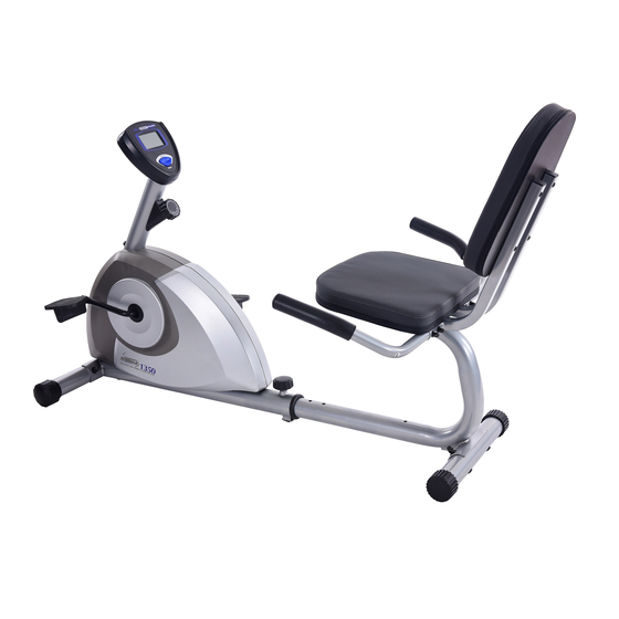
Product May Vary Slightly
From Pictured.
2008 Stamina Products, Inc.
Advertisement
Table of Contents

Related Manuals for Stamina 1350


Summary of Contents for Stamina 1350
- Page 1 Follow all safety instructions in this manual. When calling for parts or service, please specify the following number. Model#: 15-1350 STAMINA PRODUCTS MADE IN CHINA Product May Vary Slightly From Pictured. 2008 Stamina Products, Inc.
-
Page 2: Table Of Contents
The Magnetic Recumbent 1350 Bike should be used by only one person at a time. The Magnetic Recumbent 1350 Bike is for consumer use only. It is not for use in public or semipublic facilities. Use two people to move the Magnetic Recumbent 1350 Bike. -
Page 3: Customer Service
Magnetic Recumbent 1350 Bike To help you get started, we have pre-assembled most of your Magnetic Recumbent 1350 Bike at the factory with the exception of those few parts left unassembled for shipping purposes. Simply follow the few assembly instructions set forth in this manual. -
Page 4: Before You Begin
BEFORE YOU BEGIN Thank you for choosing the Magnetic Recumbent 1350 Bike. We take great pride in producing this quality product and hope it will provide many hours of quality exercise to make you feel better, look better, and enjoy life to its fullest. -
Page 5: Equipment Warning & Notice Labels
EQUIPMENT WARNING & NOTICE LABELS This chart is provided to help identify the warning & notice labels on the Magnetic Recumbent 1350 Bike. Please take a moment to familiarize yourself with all of the warning & notice labels. Label is larger than actual size... -
Page 6: Hardware Identification Chart
HARDWARE IDENTIFICATION CHART This chart is provided to help identify the hardware used in the assembly process. Place the washers or the ends of the bolts or screws on the circles to check for the correct diameter. Use the small scale to check the length of the bolts and screws. -
Page 7: Assembly Instructions
ASSEMBLY INSTRUCTIONS Place all parts from the box in a cleared area and position them on the floor in front of you. Remove all packing materials from your area and place them back into the box. Do not dispose of the packing materials until assembly is completed. - Page 8 ASSEMBLY INSTRUCTIONS STEP 4 NOTE: Install the HEX BOLTS(M6x1x37mm)(50) as shown in the illustration above. This allows the head of the bolts to fit inside the hex shape holes in the SEAT FRAMES(5, 6). Attach the RIGHT HANDRAIL(8) to the RIGHT SEAT FRAME(6) with HEX BOLTS(M6x1x37mm)(50), ARC WASHERS(M6)(64), LOCK WASHERS(M6)(66), and ACORN NUTS(M6x1)(60).
- Page 9 ASSEMBLY INSTRUCTIONS Strap A Metal Fitting Strap B Cable End Bracket Spring Hook STEP 6 Refer to illustration A. Pull the ends of the TENSION CABLE(24) and SENSOR WIRE(28) out of the FRONT FRAME(1). There are two straps attached inside of the METER POST(26) to assist when pulling the SENSOR WIRE(28) and the TENSION CABLE(24) through the METER POST(26).
- Page 10 ASSEMBLY INSTRUCTIONS STEP 8 NOTE: The RIGHT PEDAL(35) has R stamped on the end of the pedal shaft. The RIGHT PEDAL(35) has right hand threads and is tightened by turning clockwise. The LEFT PEDAL(34) has L stamped on the end of the pedal shaft. The LEFT PEDAL(34) has left hand threads and is tightened by turning counter clockwise.
-
Page 11: Set Up Instructions
SET UP INSTRUCTIONS Place the Magnetic Recumbent 1350 Bike in the area where it will be used. It is recommended that the Magnetic Recumbent 1350 Bike be placed on an equipment mat. The Magnetic Recumbent 1350 Bike is approximately 61 3/4 inches long (max.) x 27 1/2 inches wide x 36 inches tall. (These dimensions may vary up to one inch.) An area 4 feet wide x 7 feet long is required for safe operation of the Magnetic... -
Page 12: Operational Instructions
CAUTION: Do not attempt to adjust the seat while you are on the Magnetic Recumbent 1350 Bike. Always tighten the ADJUSTMENT KNOB(37) after adjusting the seat to a new position. - Page 13 OPERATIONAL INSTRUCTIONS USING THE METER POWER ON : Pedal movement or push the button. POWER OFF : Automatic shut off after four minutes of inactivity. MODE/RESET BUTTON: Press to select display functions, include SCAN, TIME, SPEED, DISTANCE, and CALORIES. Press and hold for three seconds to reset all functions to zero.
-
Page 14: Storage
Adjust the REAR FRAME(3) into the FRONT FRAME(1) to the shortest position. The Magnetic Recumbent 1350 Bike is approximately 39 3/4 inches long x 27 1/4 inches wide x 32 1/4 inches tall. These dimensions will vary. Please measure your Magnetic Recumbent 1350 Bike if exact dimensions are needed. -
Page 15: Conditioning Guidelines
CONDITIONING GUIDELINES How you begin your exercise program depends on your physical condition. If you have been inactive for several years or are severely overweight, start slowly and increase your workout time gradually. Increase your workout intensity gradually by monitoring your Remember to follow these essentials: Have your doctor review your training and diet programs. -
Page 16: Warm-Up And Cool-Down
WARM-UP and COOL-DOWN Warm-Up The purpose of warming up is to prepare your body for exercise and to minimize injuries. Warm up for two to five minutes before strength training or aerobic exercising. Perform activities that raise your heart rate and warm the working muscles. Activities may include brisk walking, jogging, jumping jacks, jump rope, and running in place Stretching Stretching while your muscles are warm after a proper warm-up and again after your strength... -
Page 17: Warranty
To implement this limited warranty, send a written notice stating your name, date, and place of purchase and a brief description of the defect along with your receipt to Stamina Products, Inc. P.O. Box 1071, Springfield Missouri, USA, 65801-1071, or email us at customerservice@staminaproducts.com, or call us at 1-800-375-7520. -
Page 18: Product Parts Drawing
PRODUCT PARTS DRAWING FRONT Strap A Strap B BACK... -
Page 19: Parts List
PARTS LIST PART# PART NAME Front Frame Front Stabilizer Rear Frame Rear Stabilizer Left Seat Frame Right Seat Frame Left Handrail Right Handrail Crank Bearing Housing Ball Bearing Inside Bearing Collar Outside Bearing Collar Bearing Washer Bearing Snap Washer Bearing Nut Pulley V-Ribbed Belt Idler Arm... - Page 20 PARTS LIST PART# PART NAME Bolt, Button Head (M8 x 1.25 x 15mm) Bolt, Button Head (M10 x 1.5 x 122mm) Bolt, Hex Head (M6 x 1 x 37mm) Bolt, Round Head (M6 x 1 x 35mm) Bolt, Flat Head (M10 x 1.5 x 20mm) Bolt, Flat Head (M10 x 1.5 x 35mm) Screw, Round Head (M5 x 0.8 x 15mm) Screw, Flat Head (M5 x 0.8 x 10mm)
-
Page 21: Notes
NOTES... -
Page 22: Fax/Mail Ordering Form
PART # EXAMPLE: CUSTOMER SERVICE CUSTOMER SERVICE Fax: (417) 889-8064 customerservice@staminaproducts.com www.staminaproducts.com Detach and Mail or Fax the Form Below Stamina Products, Inc. P.O. Box 1071 Springfield, MO 65801-1071 State: Work Phone #: ( DESCRIPTION Rear Unit Assembly ONLINE MAIL STAMINA PRODUCTS, INC.