
Related Manuals for Samson 3724


Summary of Contents for Samson 3724
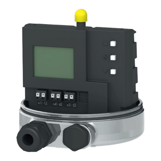
- Page 1 EB 8395 EN Translation of original instructions Type 3724 Positioner (cover removed) Type 3724 Electropneumatic Positioner Firmware version 1.01 Edition October 2018...
- Page 2 Î For the safe and proper use of these instructions, read them carefully and keep them for later reference. Î If you have any questions about these instructions, contact SAMSON‘s After-sales Service Department (aftersalesservice@samson.de). The mounting and operating instructions for the devices are included in the scope of delivery.
-
Page 3: Table Of Contents
Contents Safety instructions and measures ..............5 Notes on possible personal injury ..............7 Notes on possible property damage ..............7 Markings on the device .................9 Nameplate ....................9 Article code ....................9 Design and principle of operation ..............10 Technical data .....................12 Dimensions in mm ..................14 Measures for preparation ................15 Unpacking ....................15 Transporting ....................15... - Page 4 Contents Servicing.....................31 Preparation for return shipment ..............31 Firmware update..................31 Malfunction ....................32 Error codes ....................33 Emergency action ..................34 Decommissioning and removal ..............35 10.1 Decommissioning ..................35 10.2 Removing the positioner ................35 10.3 Disposal ......................35 Appendix ....................36 11.1 After-sales service ..................36 11.2 Code list ......................37 EB 8395 EN...
-
Page 5: Safety Instructions And Measures
SAMSON. SAMSON does not assume any liability for damage resulting from the failure to use the de- vice for its intended purpose or for damage caused by external forces or any other external factors. - Page 6 Safety instructions and measures Revisions and other modifications Revisions, conversions or other modifications of the product are not authorized by SAMSON. They are performed at the user's own risk and may lead to safety hazards, for example. Fur- thermore, the product may no longer meet the requirements for its intended use.
-
Page 7: Notes On Possible Personal Injury
Safety instructions and measures 1.1 Notes on possible personal injury WARNING Risk of personal injury due to moving parts on the valve. During initialization of the positioner and during operation, the actuator stem moves through its entire travel range. Injury to hands or fingers is possible if they are inserted into the valve. - Page 8 Safety instructions and measures Incorrect assignment of the terminals will damage the positioner and will lead to mal- function. For the positioner to function properly, the prescribed terminal assignment must be ob- served. Î Connect the electrical wiring to the positioner according to the prescribed terminal assignment.
-
Page 9: Markings On The Device
2 Markings on the device 2.1 Nameplate Configuration ID Firmware version Serial number Reference variable Supply 2.2 Article code Positioner Type 3724- 0 Housing material Housing: 1.4409 · Cover: 1.4404 Surface finish Micro-bead blasted Polished (R ≤0.6 µm) Permissible ambient temperature –20 to +80 °C... -
Page 10: Design And Principle Of Operation
(6) is changed so that the actuator (1) is pressurized or vented accordingly over the ation downstream air capacity booster (7). The The Type 3724 Positioner is delivered as a supply air is supplied to the booster (7) and ready-mounted unit on Type 3379 Pneumatic the pressure regulator (8). - Page 11 Design and principle of operation Control valve 7 Air capacity booster Sensor 8 Pressure regulator A/D converter 9 Flow regulator Microcontroller 10 Volume restriction D/A converter 11 Display i/p converter 12 Limit contacts Fig. 1: Circuit diagram EB 8395 EN...
-
Page 12: Technical Data
Design and principle of operation 3.1 Technical data Table 1: General technical data Positioner Attachment Type 3379 piston Ø: 63 mm · Effective area: 31 cm² Type 3379 piston Ø: 90 mm · Effective area: 63 cm² Travel 4 to 16 mm, adjustable in steps of 0.5 mm Reference variable w 4 to 20 mA signal range ·... - Page 13 Design and principle of operation Table 2: Limit contacts Binary contacts Two software limit contacts (min., max.) Version Reverse polarity protection, galvanic isolation Adjustment range 0 to 100 % (see section 7.7 on page 26) Step size 0.5 % Static destruction limit ± 32 V No response Non-conducting (highly resistive), I <...
-
Page 14: Dimensions In Mm
Design and principle of operation 3.2 Dimensions in mm Ød Actuator Piston Ø Ød 63 mm 69 mm Type 3379 90 mm 94 mm Fig. 2: Dimensional drawings of Type 3724 Positioner with Type 3379 Pneumatic Piston Actuator EB 8395 EN... -
Page 15: Measures For Preparation
− Observe storage instructions. note. − Avoid long storage times. 2. Check the shipment for transportation − Contact SAMSON in case of different stor- damage. Report any transportation dam- age conditions or long storage periods. age. Storage instructions 4.1 Unpacking... -
Page 16: Mounting And Start-Up
The pneumatic connections of the actuator are used (see Mounting and Operating In- Note structions of the Type 3379 Pneumatic Piston The unit consisting of the Type 3724 Posi- Actuator u EB 8315) for start-up (see sec- tioner, Type 3379 Actuator and valve is tion 7 on page 22). - Page 17 Mounting and start-up FA: actuator stem extends (air to open/ ATO) Fail-close (for globe and angle valves): Required supply pressure = Upper bench range value + 0.4 bar, minimum 1.4 bar. FE: actuator stem retracts (Air to close/ATC) Fail-open (for globe and angle valves): For tight-closing valves, the maximum signal pressure pst is roughly estimated as fol-...
-
Page 18: Electrical Connections
Mounting and start-up 5.2 Electrical connections NOTICE Incorrect assignment of the terminals will NOTICE damage the positioner and will lead to mal- An incorrect electric signal will damage the function. positioner. Connect the electrical wiring to the position- Only use a current source and never a volt- er according to the prescribed terminal as- age source. -
Page 19: Selecting Cables And Wires
Mounting and start-up 5.2.2 Selecting cables and NOTICE wires A reference variable above or below the static destruction limit will damage the posi- The minimum radial thickness of the conduc- tioner. tor insulation must be suitable for the con- Keep the reference variable within the static ductor diameter and type of insulation. -
Page 20: Operation
Operation 6 Operation To save changes to parameters in a non-vol- atile memory, proceed as follows: The positioner is operated by three pushbut- Î After changing parameters, press tons for menu navigation on the display (see button to change to Code P0 or Fig. 5): Î... - Page 21 Operation Cover Pick-up rod Pushbuttons Terminals Positioner Vent plug Actuator Fig. 6: Type 3724 Positioner mounted on Type 3379 Pneumatic Piston Actuator EB 8395 EN...
-
Page 22: Operating The Positioner
Operating the positioner 7 Operating the positioner Volume restriction Q The volume restriction serves to adapt the air output capacity to the size of the actuator. NOTICE Two fixed settings are possible (refer to sec- The process is disturbed by the movement of tion 7.3). -
Page 23: Adapting The Display
Operating the positioner 7.1 Adapting the display Reading after connecting the electrical sig- The display reading direction can be rotated Code P0 is displayed. The fault indication by 180°. If the displayed data appear up- icon and S (fail-safe position) appear on the side down, proceed as follows: display when the positioner has not yet been Press... -
Page 24: Adjusting The Volume Restriction Q
Operating the positioner If no settings are entered within three min- Setting to MIN utes, the enabled configuration function be- − Actuators with a transit time ≥ 0.4 s do comes invalid. not require the air flow rate to be restrict- 7.3 Adjusting the volume re- Setting to MAX striction Q... -
Page 25: Entering The Opening Direction/Direction Of Action
Operating the positioner 7.4 Entering the opening direc- 7.5 Entering the direction of tion/direction of action action − AIR TO OPEN (ATO) applies to a valve The direction of action (P7) is set to increas- opening as the signal pressure increases. ing/increasing by default. -
Page 26: Adjusting The Limit Contacts
Operating the positioner 7.7 Adjusting the limit contacts 7.8 Setting other parameters The following table lists all the parameter The electronic limit contact can be triggered codes and their default settings. If you want by the position of pick-up rod exceeding or to change the default setting of a parameter, falling below an adjustable switching point. -
Page 27: Initialization
Operating the positioner 7.9 Initialization During initialization the positioner adapts it- self optimally to the friction conditions and the signal pressure required by the control valve. to select Code P15. Press NOTICE Press and hold for six seconds. 6-5-4-3- 2-1- is counted down on the display. The process is disturbed by the movement of the actuator stem. -
Page 28: Zero Calibration
Operating the positioner 7.10 Zero calibration Canceling initialization The initialization can be canceled by press- In case of inconsistencies in the closed posi- tion of the valve (e.g. with soft-seated plugs), − ESC blinks on the display. it might be necessary to recalibrate zero. En- able configuration as described in sec- −... -
Page 29: Manual Mode
Operating the positioner 7.11 Manual mode Canceling zero calibration The zero calibration can be canceled by The valve position can be moved as follows pressing using the Manual mode function: − ESC blinks on the display. Enable configuration as described in section 7.2. -
Page 30: Reset
Operating the positioner 7.12 Reset Positioner that has not been initialized Press for a long time to move the A reset causes an initialization to be undone valve manually. and all parameters settings are reset to the The valve is only moved in one direction un- default settings (see code list in sec- controlled. -
Page 31: Servicing
Contact your local SAMSON engineering these instructions is performed without and sales office or subsidiary (www.samson. prior agreement by SAMSON's After-sales de > About SAMSON > Sales offices) to re- Service department. quest a firmware update. − Only use original spare parts by... -
Page 32: Malfunction
Malfunction 9 Malfunction Reset error codes The E0 and E8 error codes can be reset as In case of a fault, the fault indication icon follows: is displayed. Press to select the error code. If the fault indication icon appears after a parameter code setting has been changed, this indicates that this setting does not match the values determined during initialization. -
Page 33: Error Codes
Malfunction 9.1 Error codes In case of a fault, the fault indication icon is displayed. The errors listed in the following table are assigned to error classes: Error class 1: No operation possible Error class 2: Manual operation only possible Error class 3: Manual operation and closed-loop control possible Code Description... -
Page 34: Emergency Action
Recommended action Check positioner mounting and re-initialize the positioner. Error code can be reset (see section 9). Device error (internal) Return positioner to SAMSON AG for repair. 9.2 Emergency action Upon failure of the air supply or electric signal, the positioner vents the actuator, causing the valve to move to the fail-safe position determined by the actuator. -
Page 35: Decommissioning And Removal
Decommissioning and removal 10 Decommissioning and 10.3 Disposal removal Î Observe local, national and internation- al refuse regulations. NOTICE Î Do not dispose of components, lubricants The process is disturbed by interrupting and hazardous substances together with closed-loop control. your other household waste. Do not mount or service the positioner while the process is running and only after isolat- ing the plant by closing the shut-off valves. -
Page 36: Appendix
You can reach the After-sales Service De- partment at aftersalesservice@samson. Addresses of SAMSON AG and its subsid- iaries The addresses of SAMSON AG, its subsid- iaries, representatives and service facilities worldwide can be found on our website (www.samson.de) or in all SAMSON prod- uct catalogs. -
Page 37: Code List
Appendix 11.2 Code list Code Display, values Description [default setting] Note: Codes marked by an asterisk (*) indicate that the positioner needs to be re-initialized afterwards Status reading with The reading indicates the valve position in % when the positioner is basic information initialized. - Page 38 Appendix Code Display, values Description [default setting] Set point cutoff Upper tight-closing function: increase (end position If w reaches up to 99 % towards the final value that causes the valve w >) to open, the actuator is immediately completely filled with air (with ON/[OFF] ATO - air to open) or vented (with ATC - air to close).
- Page 39 EB 8395 EN...
- Page 40 EB 8395 EN SAMSON AKTIENGESELLSCHAFT Weismüllerstraße 3 · 60314 Frankfurt am Main, Germany Phone: +49 69 4009-0 · Fax: +49 69 4009-1507 samson@samson.de · www.samson.de...