Table of Contents
Advertisement
Quick Links
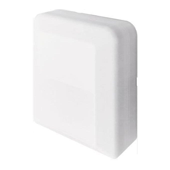
UTY-VTGX
INSTALLATION MANUAL
NETWORK CONVERTOR
For authorized service personnel only.
INSTALLATIONSANLEITUNG
NETZWERKKONVERTER
Nur für autorisiertes Fachpersonal.
MANUEL D'INSTALLATION
Pour le personnel agréé uniquement.
MANUAL DE INSTALACIÓN
Únicamente para personal de servicio autorizado.
MANUALE DI INSTALLAZIONE
CONVERTITORE DI RETE
A uso esclusivo del personale tecnico autorizzato.
ΕΓΧΕΙΡΙΔΙΟ ΕΓΚΑΤΑΣΤΑΣΗΣ
ΜΕΤΑΤΡΟΠΕΑΣ ΔΙΚΤΥΟΥ
Μόνο για εξουσιοδοτημένο τεχνικό προσωπικό.
MANUAL DE INSTALAÇÃO
Apenas para técnicos autorizados.
РУКОВОДСТВО ПО УСТАНОВКЕ
Только для авторизованного обслуживающего персонала.
MONTAJ KILAVUZU
Yalnızca yetkili servis personeli için.
仅针对授权的专业维修人员。
ADAPTATEUR RESEAU
CONVERTIDOR DE RED
CONVERSOR DE REDE
СЕТЕВОЙ КОНВЕРТОР
AÐ DÖNÜÞTÜRÜCÜ
安装说明书
安装说明书
网络信号转换器
[Original instructions]
PART NO. 9374707119-02
Advertisement
Table of Contents

Summary of Contents for Fujitsu Airstage UTY-VTGX
- Page 1 INSTALLATION MANUAL NETWORK CONVERTOR For authorized service personnel only. INSTALLATIONSANLEITUNG NETZWERKKONVERTER Nur für autorisiertes Fachpersonal. MANUEL D’INSTALLATION ADAPTATEUR RESEAU Pour le personnel agréé uniquement. MANUAL DE INSTALACIÓN CONVERTIDOR DE RED Únicamente para personal de servicio autorizado. MANUALE DI INSTALLAZIONE CONVERTITORE DI RETE UTY-VTGX A uso esclusivo del personale tecnico autorizzato.
-
Page 2: Table Of Contents
INSTALLATION MANUAL This mark indicates procedures which, if improp- CAUTION erly performed, might possibly result in personal PART NO. 9374707119-02 harm to the user or damage to property. NETWORK CONVERTOR Pay abundant care when transporting this unit because it is a precision device. -
Page 3: Electrical Requirement
3. ELECTRICAL REQUIREMENT 5. WIRING WARNING Size Cable type Remarks 22AWG LEV- Before starting installation work, turn off the power of this unit and the EL4 (NEMA) connection destination. Do not turn on the power again until installa- ORKS Transmis- 0.33 mm nonpolar 2 tion is completed. -
Page 4: Wiring Method
[Example of connecting single split type indoor unit in a parallel arrange- 5. 1. Wiring method ment] 5. 1. 1. Setting method when connecting a single split Case 1: For non-polar 2 wire indoor unit Wired Group of Single Split System *1 *2 Transmission remote Cable... -
Page 5: Unit Wiring
5. 2. Unit wiring 6. INSTALLING THE NETWORK CONVERTOR 5. 2. 1 Transmission and Remote controller cable WARNING Transmission cable Always use the accessories and specifi ed installation work parts. Check the state of the installation parts. Not using the specifi ed parts 25 mm (1 in) will cause units to fall off, electric shock, fi... -
Page 6: Connection Of Remote Controller Cable
Case 1: For non-polar 2 wire 7. CONNECTION OF REMOTE CONTROLLER CABLE Remote controller cable Transmission cable CAUTION Cable tie When connecting the remote controller cable to the indoor unit, do not (Accessories) connect it to the outdoor unit or the power terminal block. It may cause a failure. -
Page 7: Circuit Board Setting
Case 2: For polar 3 wire 8. CIRCUIT BOARD SETTING Modify the cable as per below methods. Set network convertor rotary switch SET1, and DIP switch SET2, SET3 Use a tool to cut off the terminal on the end of the remote controller cable, and then remove the insulation from the cut end of the cable as shown in Fig. -
Page 8: Turning On The Power
10. 2. Error code 9. TURNING ON THE POWER When error occurs in the remote controller connected to the Network (1) Check the network convertor wiring and switch settings on the convertor, please refer to the installation manual of the remote control- circuit board.


