Sony HT-DDW650 Operating Instructions (HT-DDW650) Operating Instructions Manual
Home theater system
Hide thumbs
Also See for HT-DDW650 Operating Instructions (HT-DDW650):
- Connection and installation manual (2 pages) ,
- Speakers connection (1 page) ,
- Supplementary manual (1 page)
Table of Contents
Advertisement
Home Theater
System
Operating Instructions
Owner's Record
The model and serial numbers are located at the rear of the unit. Record the serial
number in the space provided below. Refer to them whenever you call upon your Sony
dealer regarding this product.
Model No.
HT-DDW650
© 2003 Sony Corporation
4-244-183-71(1)
Serial No.
Advertisement
Table of Contents

Related Manuals for Sony HT-DDW650 Operating Instructions (HT-DDW650)


Summary of Contents for Sony HT-DDW650 Operating Instructions (HT-DDW650)
-
Page 1: Operating Instructions
Operating Instructions Owner’s Record The model and serial numbers are located at the rear of the unit. Record the serial number in the space provided below. Refer to them whenever you call upon your Sony dealer regarding this product. Model No. - Page 2 * Manufactured under license from Dolby Laboratories. “Dolby”, “Pro Logic” and the double-D symbol are trademarks of Dolby Laboratories. ** “DTS” and “DTS Digital Surround” are registered trademarks of Digital Theater Systems, Inc. is a U.S. registered ® partner, Sony ® NERGY...
-
Page 3: Table Of Contents
Table of Contents List of Button Locations and Reference Pages Main unit ... 5 Hooking Up the Components Required cords ... 6 Antenna hookups ... 7 Audio component hookups ... 8 DVD Player/Video Cassette Recorder hookups ... 9 Video component hookups ... 10 Digital component hookups ... -
Page 4: About This Manual
About This Manual The HT-DDW650 consists of: – Receiver – Speaker system • Front/surround speakers • Center speaker • Sub woofer The instructions in this manual describe the controls on the receiver. You can also use the controls on the supplied remote if they have the same or similar names as those on the receiver. -
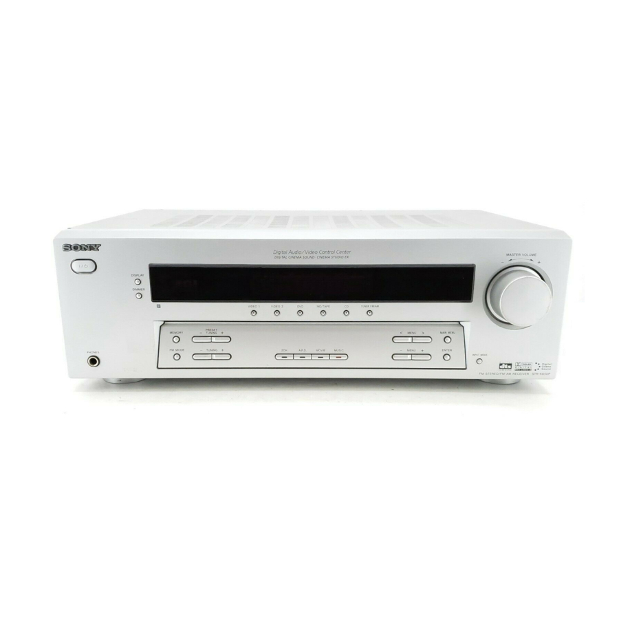
Page 5: Main Unit
List of Button Locations and Reference Pages How to use this page Use this page to find the location of buttons that are mentioned in the text. Main unit ALPHABETICAL ORDER A – L A.F.D. (button/indicator) w; (23- CD 9 (21) DIMMER 3 (22) DISPLAY 2 (22, 42) Display qa (22) -
Page 6: Hooking Up The Components
Hooking Up the Components Required cords The following optional connection cords A – E are required when you hook up the components (pages 8 – 11). A Audio cord (supplied (1 only)) White (L) Red (R) B Audio/video cord (not supplied) Yellow (video) White (L/audio) Red (R/audio) -
Page 7: Antenna Hookups
Antenna hookups ANTENNA DIGITAL OPTICAL VIDEO 2 DVD IN COAXIAL * The shape of the connector varies depending on the area code. Notes on antenna hookups • To prevent noise pickup, keep the AM loop antenna away from the receiver and other components. -
Page 8: Audio Component Hookups
Audio component hookups MD or Tape deck INPUT OUTPUT LINE LINE ANTENNA DIGITAL OPTICAL VIDEO 2 75Ω DVD IN COAXIAL COAXIAL MD/TAPE OUTPUT LINE CD player MONITOR VIDEO IN VIDEO IN VIDEO OUT VIDEO OUT VIDEO IN AUDIO AUDIO IN AUDIO IN AUDIO OUT AUDIO IN VIDEO 2 VIDEO 1... -
Page 9: Dvd Player/Video Cassette Recorder Hookups
DVD Player/Video Cassette Recorder hookups DIGITAL ANTENNA OPTICAL VIDEO 2 VIDEO IN VIDEO IN 75Ω DVD IN COAXIAL COAXIAL AUDIO IN AUDIO IN MD/TAPE VIDEO 2 DVD & VCR LINE LINE IN 1 (FROM ANT.) AUDIO (TO TV) VIDEO Note If your TV has COMPONENT VIDEO input jacks, you can use a component video cord (not supplied) to connect the DVD Player/Video Cassette Recorder to your TV. -
Page 10: Video Component Hookups
Video component hookups If you are not going to hookup a DVD Player/Video Cassette Recorder, you can hookup your video components as shown below. DIGITAL OPTICAL VIDEO 2 DVD IN COAXIAL Note on video component hookups You can connect your TV’s audio output jacks to the VIDEO 2 AUDIO IN jacks on the receiver and apply sound effects to the audio from the TV. -
Page 11: Digital Component Hookups
Digital component hookups If you are not going to hookup a DVD Player/Video Cassette Recorder, you can hookup your digital components as shown below. Connect the digital output jacks of your DVD player and satellite tuner (etc.) to the receiver’s digital input jacks to bring the multi channel surround sound of a movie theater into your home. -
Page 12: Other Hookups
Other hookups FRONT SPEAKERS Connecting the AC power cord Before connecting the AC power cord of this receiver to a wall outlet, connect the speaker system to the receiver (page 13). Connect the AC power cord(s) of your audio/ video components to a wall outlet. AC power cord CENTER SURROUND... -
Page 13: Hooking Up And Setting Up The Speaker System
Hooking Up and Setting Up the Speaker System Speaker system hookups Required cords A Speaker cords (supplied) (–) Active sub woofer INPUT AUDIO To a wall outlet (Switch the power (POWER) to off before connecting the power cord.) MONITOR VIDEO OUT AUDIO WOOFER Center speaker... - Page 14 Speaker system hookups (continued) To prevent speaker vibration or movement while listening, attach the supplied foot pads at the bottom of the speakers. Notes • Connect the long speaker connecting cords to the surround speaker terminals and the short speaker connecting cords to the front and center speaker terminals.
-
Page 15: Performing Initial Setup Operations
To avoid damaging your speakers Make sure that you turn down the volume before you turn off the receiver. When you turn on the receiver, the volume remains at the level you turn off the receiver. Performing initial setup operations Once you have hooked up the speakers and turned on the power, clear the receiver’s memory. -
Page 16: Specifying The Speaker Parameters
MENU. (To reset to “MICRO SP.”, do the same procedure.) The setting for Micro Satellite Speaker (MICRO SP.) has been programmed to optimize the sound balance. If you use Sony’s Micro Satellite Speakers, select “MICRO SP.”. Caution When you use Micro Satellite Speakers and the speaker size is set to “LARGE”, you may not obtain... - Page 17 x Front speaker distance ( XX ft.) Set the distance from your listening position to the front speakers (A on page 15). x Center speaker distance ( XX ft.) Set the distance from your listening position to the center speaker. Center speaker distance should be set from a distance equal to the front speaker distance (A on page 15) to a distance 5 feet closer to your listening position (B on...
- Page 18 Multi channel surround setup (continued) The surround speaker placement parameter is designed specifically for implementation of the Digital Cinema Sound modes with virtual elements. With the Digital Cinema Sound modes, speaker placement is not as critical as other modes. All modes with virtual elements were designed under the premise that the surround speaker would be located behind the listening position, but presentation remains...
-
Page 19: Adjusting The Speaker Level
x Surround speaker size ( XXXXX) • If you connect large speakers that will effectively reproduce bass frequencies, select “LARGE”. Normally, select “LARGE”. However, if the front speakers are set to “SMALL”, you cannot set the surround speakers to “LARGE”. •... -
Page 20: Checking The Connections
Multi channel surround setup (continued) Listening to the sub woofer POWER indicator First, turn down the volume on the receiver. The volume should be set to minimum before you begin playing the program source. Turn on the receiver and select the program source. -
Page 21: Basic Operations
Basic Operations Selecting the component Input Selector buttons Press the input selector button to select the component you want to use. To select Press DVD PLAYER/VIDEO CASSETTE RECORDER (DVD mode) DVD PLAYER/VIDEO VIDEO 1 CASSETTE RECORDER (VIDEO mode) Other VCR VIDEO 2 MD or Tape deck MD/TAPE... -
Page 22: Changing The Display
Changing the display DIMMER Press DIMMER repeatedly to adjust the brightness of the display (3 steps). However, when you press any button, the display becomes the brightest setting temporary. DISPLAY Each time you press DISPLAY, the display changes cyclically as follows: Index name of the component* t Selected component t Sound field applied to the program source... -
Page 23: Enjoying Surround Sound
Enjoying Surround Sound You can take advantage of surround sound simply by selecting one of the receiver’s pre- programmed sound fields. They bring the exciting and powerful sound of movie theaters and concert halls into your home. You can also customize the sound fields to obtain the sound you want by changing the surround parameter. -
Page 24: Selecting A Sound Field
In collaboration with Sony Pictures Entertainment, Sony measured the sound environment of their studios and integrated the data of the measurement and Sony’s own DSP (Digital Signal Processor) technology to develop “Digital Cinema Sound”. In a home theater, “Digital Cinema Sound” simulates an... - Page 25 C.ST.EX A (Cinema Studio EX A) Reproduces the sound characteristics of the Sony Pictures Entertainment “Cary Grant Theater” cinema production studio. This is a standard mode, great for watching most any type of movie. x C.ST.EX B (Cinema Studio EX B) Reproduces the sound characteristics of the Sony Pictures Entertainment “Kim Novak...
-
Page 26: Understanding The Multi Channel Surround Displays
Understanding the multi channel surround displays L F E 1 SW: Lights up when sub woofer selection is set to “YES” (page 18) and the audio signal is output from the SUB WOOFER jacks. 2 SP: Lights up when you turn on the receiver. Note Does not light up when you connect headphones to the PHONES jack. -
Page 27: Customizing Sound Fields
qs Playback channel indicators: The letters (L, C, R, etc.) indicate the channels being played back. The boxes around the letters vary to show how the receiver downmixes the source sound (based on the speakers settings). When using sound fields like “C.ST.EX”, the receiver adds reverberation based on the source sound. - Page 28 Customizing sound fields (continued) Front balance ( Lets you adjust the balance between front left and right speakers. Center level (CTR XXX dB) Lets you adjust the level of the center speaker. Surround left level (SUR.L. XXX dB) Lets you adjust the level of the surround left speaker.
-
Page 29: Receiving Broadcasts
Receiving Broadcasts Before receiving broadcasts, make sure you have connected FM and AM antennas to the receiver (page 7). Direct tuning You can enter a frequency of the station you want directly by using the numeric buttons on the supplied remote. For details on the buttons used in this section, see pages 35–39. -
Page 30: Automatic Tuning
Automatic tuning If you don’t know the frequency of the station you want, you can let the receiver scan all available stations in your area. Press TUNER FM/AM repeatedly to select the FM or AM band. The last received station is tuned in. Press TUNING + or TUNING –. -
Page 31: Tuning To Preset Stations
Tuning to preset stations You can tune the preset stations by either of the following two ways. Scanning the preset stations Press TUNER FM/AM. The last received station is tuned in. Press PRESET TUNING + or PRESET TUNING – repeatedly to select the preset station you want. -
Page 32: Other Operations
Other Operations Naming preset stations and program sources You can enter a name (index name) of up to 8 characters for preset stations and program sources. These names (for example, “VHS”) appear in the receiver’s display when a station or program source is selected. Note that no more than one name can be entered for each preset station or program source. -
Page 33: Adjustments Using The Set Up Menu
Recording on a video tape You can record from a VCR, a TV or a DVD player using the receiver. You can also add audio from a variety of audio sources when editing a video tape. See the operating instructions of your VCR or DVD player if you need help. -
Page 34: Changing The Command Mode Of The Receiver
Changing the command mode of the receiver This function is useful when you use 2 Sony receivers in the same room. Turn off the receiver. Hold down ENTER and press 1/u to turn on the receiver. “C.MODE.AVX” appears in the display. -
Page 35: Operations Using The Remote Rm-Pp65
Operations Using the Remote RM-PP65 You can use the remote RM-PP65 to operate the components in your system. You can also use this remote to operate the DVD PLAYER/ VIDEO CASSETTE RECORDER (SLV-D300P). Before you use your remote Inserting batteries into the remote Insert R6 (size-AA) batteries with the + and –... - Page 36 SET UP, LEVEL, TONE and NAME. MENU. Turns the audio and video components on or Operations Function Receiver/ Turns off the receiver and other Sony audio/ Satellite tuner/ video components. CD player/ DVD PLAYER/ VIDEO RECORDER/ MD deck Receiver Use with “SHIFT”...
- Page 37 Remote Operations Function Button ENTER After selecting a DVD PLAYER/ channel, disc or track VIDEO using the numeric CASSETTE buttons, press to enter RECORDER the value. (VIDEO mode)/ Satellite tuner/ MD deck/ Tape deck DVD PLAYER/ Selects output signal VIDEO from aerial terminal: CASSETTE TV signal or VCR...
-
Page 38: Changing The Factory Setting Of An Input Selector Button
VCR (command mode VTR 3*) TV (SONY) DSS (Digital Satellite Receiver) Tuner * Sony VCRs are operated with a VTR 2 or 3 setting. These correspond to 8mm and VHS respectively. Now you can use the MD/TAPE button to control the Tape Deck B. - Page 39 Controlling other TVs with the remote commander The remote commander is pre-programmed to control non-Sony TVs. If your TV is listed in the following table, set the appropriate manufacturer’s code number. Hold down TV ?/1 and enter your TV’s code number using the number buttons.
-
Page 40: Additional Information
If you have any question or problem concerning your receiver, please consult your nearest Sony dealer. Troubleshooting If you experience any of the following... - Page 41 There is no sound from a specific component. • Check that the component is connected correctly to the audio input jacks for that component. • Check that the cord(s) used for the connection is (are) fully inserted into the jacks on both the receiver and the component.
- Page 42 If the problem persist Consult your nearest Sony dealer. Clearing the receiver’s memory To clear All memorized settings page 15...
-
Page 43: Specifications
Specifications AUDIO POWER SPECIFICATIONS POWER OUTPUT AND TOTAL HARMONIC DISTORTION: With 8 ohm loads, both channels driven, from 40 – 20,000 Hz; rated 70 watts per channel minimum RMS power, with no more than 0.7 % total harmonic distortion from 250 milliwatts to rated output. - Page 44 Specifications (continued) AM tuner section Tuning range With 10-kHz tuning scale: 530 – 1710 kHz With 9-kHz tuning scale: 531 – 1710 kHz Antenna Intermediate Frequency Usable sensitivity Harmonic distortion Selectivity At 9 kHz: At 10 kHz: 4) You can change the AM tuning scale to 9 kHz or 10 kHz.
- Page 45 Continuous RMS power output (6 ohms, 20 – 250 Hz) 100 W Reproduction frequency range 28 Hz – 200 Hz High frequency cut-off frequency 150 Hz Input LINE IN (input pin jacks) Power requirements 120 V AC, 60 Hz Power consumption 100 W Approx.
-
Page 46: Tables Of Settings Using The Main Menu Button
Tables of settings using the MAIN MENU button You can make various settings using the MAIN MENU, MENU tables below show each of the settings that these buttons can make. Press MAIN MENU Press MENU repeatedly to select to select LEVEL CTR XXX dB SUR.L. -
Page 47: Adjustable Parameters For Each Sound Field
Adjustable parameters for each sound field The adjusted BASS and TREB. parameters are applied to all sound fields. 2CH ST. A.F.D. AUTO DOLBY PL PLII MOV PLII MUS C.ST.EX A C.ST.EX B C.ST.EX C HALL JAZZ CONCERT PCM 96K The adjusted LEVEL parameters are applied to all the sound fields except for EFCT. parameter. For EFCT. - Page 48 US Sony Corporation Printed in Malaysia...