Janome Continental M7 Professional Service Manual
Hide thumbs
Also See for Continental M7 Professional:
- Instructions (3 pages) ,
- Instruction book (144 pages)
Table of Contents
Advertisement
Advertisement
Table of Contents

Related Manuals for Janome Continental M7 Professional


Summary of Contents for Janome Continental M7 Professional
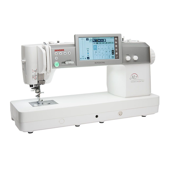
- Page 1 First Edition: 06 August 2019 SERVICE MANUAL MODEL: Continental M7 Professional...
-
Page 2: Table Of Contents
INDEX Changing external parts Face plate ................................. 1 Top cover ................................1 Belt cover ................................. 2 Base ................................. 2 Power supply cover ............................3 Thread cutter cover ............................3 Front cover ............................... 4 Rear cover ................................ 5 Arm thread guide unit ............................6 Replacing Electronic Components Changing the printed circuit board A ........................ -
Page 3: Changing External Parts
Changing external parts (1) Face plate To remove: 1. Remove the setscrew A and remove the face plate. To attach: Setscrew A 1. Attach the face plate with the setscrew A. Face plate Top cover To remove: Setscrew B Setscrew B 1. -
Page 4: Belt Cover
Changing external parts (2) Hook Belt cover Belt cover To remove: 1. Remove the top cover. (Refer to page 1) Remove the caps and setscrews A (4 pcs.) and Setscrew A remove belt cover. To attach: Hook 1. Attach the belt cover and tighten the setscrews A Setscrew A (4 pcs.). -
Page 5: Power Supply Cover
Changing external parts (3) Power supply cover To remove: 1. Remove the setscrews A (3 pcs) and remove the power supply cover. Setscrew A To attach: 1. Attach the power supply cover with setscrews A (3 pcs.). Power supply cover Setscrew A Thread cutter cover To remove:... -
Page 6: Front Cover
Changing external parts (4) Setscrew A Front cover Setscrew A To remove: 1. Remove the face plate, top cover and belt cover. (Refer to pages 1 and 2) 2. Loosen the setscrews A (5 pcs.). 3. Remove the setscrews B (2 pcs.). 4. -
Page 7: Rear Cover
Changing external parts (5) Rear cover To remove: Setscrew Setscrew 1. Remove the setscrews (3 pcs.) and remove the rear cover. To attach: 1. Attach the rear cover with the setscrews (3 pcs.). Setscrew... -
Page 8: Arm Thread Guide Unit
Changing external parts (6) Arm thread guide unit Setscrew To remove: 1. Remove the face plate and top cover. (Refer to page 1) 2. Loosen the setscrews (2 pcs.), and remove the arm thread guide unit. To attach: 1. Follow the steps of removal procedure in reverse. Setscrew Arm thread guide unit... -
Page 9: Changing The Printed Circuit Board A
Changing the printed circuit board A Setscrew A To remove: 1. Remove the face plate, top cover, belt cover and front cover. (Refer to page 1 to 4) Belt cord guide 2. Remove the setscrews A (2 pcs.) and remove the belt cord guide. -
Page 10: Changing The Printed Circuit Board F And Slide Volume
Changing the printed circuit board F and slide volume Printed circuit board F Connector for printed circuit board F Setscrew A To remove: 1. Remove the front cover. (Refer to page 4) 2. Disconnect the connector for printed circuit board F. 3. -
Page 11: Changing The Front Panel
Changing the front panel Front panel 2 Setscrew B Setscrew B To remove: Setscrew A Setscrew A 1. Remove the front cover. (Refer to page 4) 2. Remove the setscrews A (2 pcs.). Unhook the front panel 2 from the front panel unit and remove the front panel 2. -
Page 12: Changing The Lcd Unit And Lcd Supporter Plate
Changing the LCD unit and LCD supporter plate Front panel unit LCD supporter plate LCD unit Setscrew B To remove: 1. Remove the front cover, front panel 2 and front panel unit. (Refer to pages 4 and 8) 2. Remove the setscrews A (4 pcs.) and LCD unit. 3. -
Page 13: Wiring Diagram
Wiring diagram Refer to this wiring diagram for locating the connectors on the printed circuit board A. (Front side) Printed circuit board F (Black 18P) Printed circuit board U2 Slide volume (Black 3P) (Flexible cable) Rotary encoder (White 6P) Printed circuit board L1 (Black 2P) Printed circuit board L1 (Blue 2P) Printed circuit board L3 (Red 2P) Printed circuit board L2 (White 2P) -
Page 14: Needle Drop Position Adjustment
Needle drop position adjustment When you enter the factory setting mode, the needle should be positioned in the center of the needle plate hole. When the “Bobbin” key is pressed, the clearance between the side of the needle and needle hole should be 0.2 mm or more. -
Page 15: Backlash Between Hook Drive Gear And Lower Shaft Gear
Backlash between hook drive gear and lower shaft gear The gears should turn smoothly and rotary play of the hook should be 0.8 mm or less when the tip of hook is within the width of the feed dog as shown below. Width of feed dog 1. -
Page 16: Hook Timing Adjustment
Hook timing adjustment The amount of ascending travel of the needle bar from its lowest position to the position where the tip of the rotary hook exactly meets the right side of the needle in the left needle position (“0.0”) should be 3.70 to 4.00 mm. The tip of the rotary hook exactly meets the right side of Needle #14... -
Page 17: Needle Bar Height Adjustment
Needle bar height adjustment Before proceeding with this adjustment, check the hook timing. (Refer to page 14) The distance between the upper edge of the needle eye and the tip of the hook should be in the range of 1.6 to 2.0mm when the tip of the hook meets right side of the needle in the left needle position (“0.0”) as the needle ascends from its lowest position. -
Page 18: Clearance Between Needle And Tip Of The Rotary Hook Adjustment (1)
Clearance between needle and tip of the rotary hook adjustment (1) The clearance between the needle and the tip of the rotary hook should be between -0.10 to +0.05 mm. Clearance adjustment 1 1. Remove the face plate and top cover. (Refer to page 1) Test pin 2. -
Page 19: Clearance Between Needle And Tip Of The Rotary Hook Adjustment (2)
Clearance between needle and tip of the rotary hook adjustment (2) The clearance between the needle and the tip of the rotary hook should be between -0.10 to +0.05 mm. Clearance adjustment 2 1. Remove the base. (Refer to page 2) Hook setting plate 2. -
Page 20: Height And Direction Of Presser Bar Adjustment
Height and direction of presser bar adjustment The clearance between the presser foot and the surface of the needle plate should be 6.0 mm when the presser foot is raised with the presser foot lifter. The presser foot should be parallel to the slot of the feed dog teeth when attached. Presser foot lifter button 1. -
Page 21: Feed Dog Height Adjustment
Feed dog height adjustment When the presser foot is lowered in the factory setting mode, the highest position of the feed dog should be 0.90 to 1.00 mm from the surface of the needle plate. Reverse button To adjust: Start/stop button 1. -
Page 22: To Replace Needle Thread Tension Unit
To replace needle thread tension unit Setscrew A To remove: 1. Remove the face plate, top cover, thread guide cover, front cover and arm thread guide. (Refer to pages 1, 4 and 6) 2. Loosen the setscrew A (2 pcs.) and slide the front cover toward you slightly. -
Page 23: Tension Release Mechanism Adjustment
Tension release mechanism adjustment When the presser foot lifter is raised, the tension release mechanism should work correctly. 1 Remove the face plate, top cover and front cover (Refer to pages 1 and 4). Convex is NOT set at tension release claw 2. -
Page 24: Upper Thread Tension Adjustment
Upper thread tension adjustment The standard upper thread tension should be 59 to 67 grams-force when the thread tension is set at “3.4”, measured with a #50 polyester thread being pulled at approximately 110 mm/ sec. in the direction of arrow. 1. -
Page 25: Bobbin Winder Stopper Adjustment
Bobbin winder stopper adjustment The diameter of thread wound on a bobbin should be 16.5 to 19.5 mm. 1. To adjust the thread amount for bobbin, loosen the setscrew and turn the bobbin winder stopper. Turn the bobbin winder stopper in the direction of (A) when the thread amount for bobbin is too large. -
Page 26: Needle Threader Hook Position
Needle threader hook position The threader hook comes out through the needle eye from behind when the needle threader lever is lowered. 1. Push down the threader lever and hold it just before the threader hook enters the needle eye. 2. -
Page 27: Thread Cutter Switch Adjustment
Thread cutter switch adjustment The distance between the left end of thread cutter plate slit and the left end of moving cutter should be in the range of 0.7 to 1.5 mm. 1. Turn the poewr switch off. End of thread End of moving cutter Remove the needle plate, base and thread cutter cutter plate slit... -
Page 28: Thread Drawing Lever Height Adjustment
Thread drawing lever height adjustment The maximum height of the thread drawing lever should be between 5.5 to 5.7 mm from the hook race. 1. Remove the needle plate. 2. Loosen the hexagonal socket screw. When the thread drawing lever is at the highest position, adjust the drawing lever so that the distance between the hook race and the drawing lever is 5.5 to 5.7 mm. -
Page 29: Automatic Upper Feed Withdrawal Rod Adjustment
Automatic upper feed withdrawal rod adjustment The clearance between the upper feed arm and upper feed cam should be 1.5 mm to 2.5 mm when “SM Init” key is pressed in the factory setting mode. 1. Turn the power switch ON while pressing the start/ stop button and the reverse stitch button to enter the Reverse button factory setting mode. -
Page 30: Automatic Upper Feed Adjustment (1)
Automatic upper feed adjustment (1) Adjust this part after adjusting the automatic upper feed withdrawal. The clearance between the upper feed lower shaft 2 and connecting link shaft stool should be 16.5 mm when “Dualfeed” key is pressed in the factory setting mode and the offset value is set at “0”, the balancing value is set at “5”, the stitch length value is set at “2.40”. -
Page 31: Automatic Upper Feed Adjustment (2)
Automatic upper feed adjustment (2) Adjust this part after Adjusting the automatic upper feed adjustment (1). To check: 1. Attach the dual feed foot. Reverse button 2. Remove the top cover. 3. Turn the power switch ON while pressing the start/ Start/stop button stop button and the reverse stitch button to enter the factory setting mode. -
Page 32: Upper Feed Dog (1)
Upper feed dog (1) The needle tip should be 0 to 1 mm above the surface of the needle plate when the toe of the dual feed foot touch the needle plate. To check: Reverse button 1. Attach the dual feed foot and needle #14. 2. -
Page 33: Upper Feed Dog (2)
Upper feed dog (2) To adjust: 1. Follow steps 3 to 5 of “To check” procedure on page 30 and turn the handwheel toward you to raise the Hexagonal socket bolt needle. 2. Remove the top cover and face plate. Buttonhole lever 3. -
Page 34: To Replace The Thread Take-Up Lever
To replace the thread take-up lever When you replace the thread take-up lever, insert the needle bar crank pin into the take- up lever crank as illustrated. The setscrew A (long) must hold the needle bar crank pin cut surface. Thread take-up lever Setscrew A (long) Take-up lever crank... -
Page 35: To Attach Lower Shaft
To attach lower shaft When you replace the lower shaft or the lower shaft parts, adjust the phases as shown below. The phases of the thread drawing lever cam (A) and the feed cam (B) are the same as that of the spring pin (C). -
Page 36: Synchlo Belt
Synchlo belt When you replace the synchlo belt, set the alignment Alignment mark (A) mark (A) on the belt wheel at upper left (10 degrees), the 10 degrees alignment mark (B) on the lower shaft gear at upper right as shown. Belt wheel Synchlo belt Alignment mark (B) -
Page 37: To Replace The Brushless Dc Motor And Belt Tension Adjustment
To replace the brushless DC motor and belt tension adjustment Setscrew A To remove: Printed circuit board B unit 1. Remove the face plate, top cover, belt cover, base and front cover. (Refer to pages 1, 2 and 4) 2. Remove the motor belt. 3. -
Page 38: Upper Shaft Shield Plate Position
Upper shaft shield plate position When the machine is set for zigzag stitch, the needle should start to swing 7.2 to 8.2 mm above the surface of the needle plate. 1. Attach the #14 needle. Needle #14 2 Turn the power switch on while pressing the start/stop button and reverse button to enter the factory setting mode. -
Page 39: Buttonhole Lever Position Adjustment
Buttonhole lever position adjustment If the buttonhole stitches are distorted or not balanced, refer to the troubleshooting of the instruction book. If the problem still persists, adjust as follows; 1. Turn the power switch on while pressing the start/stop button and reverse button to enter the factory setting Reverse button mode. -
Page 40: Stretch Stitch Feed Balance Adjustment
Stretch stitch feed balance adjustment Stretch stitch balance dial position 1. Attach the satin stitch foot F. 2. Set the stretch stitch feed balance dial to the neutral position. 3. Turn the power switch on while pressing the start/stop button and reverse button to enter the factory setting Neutral position Stretch stitch balance dial mode. -
Page 41: Presser Foot Lifter Stopper Position (1)
Presser foot lifter stopper position (1) The distance between the presser foot spring release base and the presser foot lifter stopper should be in the range of 39.4 mm to 39.8 mm when the presser foot is raised with the presser foot lifter. Presser foot lifter stopper Preparation: 1. -
Page 42: Presser Foot Lifter Stopper Position (2)
Presser foot lifter stopper position (2) The distance between the presser foot spring release base and the presser foot lifter should be in the range of 39.4 mm to 39.8 mm when the presser foot is raised with the presser foot lifter. To adjust: Front side of the machine 1. -
Page 43: Automatic Presser Foot Lifter Initializing Sensor Position
Automatic presser foot lifter initializing sensor position Adjust the automatic presser foot lifter initializing sensor position when the presser foot lifter motor unit is replaced. To adjust: 1. Remove the face cover, top cover and rear cover. Reverse button (Refer to pages 1, 5) 2. -
Page 44: Preseer Foot Height On Needle Plate Adjustment
Preseer foot height on needle plate adjustment Presser foot lifter button To adjust: 1. Turn the power switch on while pressing the start/stop Reverse button button and reverse button to enter the factory setting mode. Press the “Foot Up/Down” key to select the Foot Up/ Start/stop button Down adjusting mode. -
Page 45: Presser Bar Lifter Switch Position
Presser bar lifter switch position To check: Reverse button 1. Attach the zigzag foot (A) . Start/stop button 2. Turn the power switch on while pressing the start/stop button and reverse button to enter the factory setting mode. Press “Foot Sensor” key to select the foot sensor adjusting mode. -
Page 46: To Replace And Adjust The Needle Plate Sensor Switch
To replace and adjust the needle plate sensor switch To replace: To remove: 1. Remove the base. (Refer to page 2) Rear side 2. Push and turn the needle plate release dial in direction A with the screwdriver. Remove the needle plate and bobbin holder. * LED light can be too bright when the machine lay on its side. -
Page 47: To Replace The Switching Power Supply Unit
To replace the switching power supply unit To remove: 1. Remove the belt cover, power supply cover and front cover. (Refer to pages 2 to 4) 2. Disconnect the switching power supply connector (motor) (white 5P), switching power supply connector Switching ErP switch (control) (white 4P) and ErP switch connector (green... -
Page 48: Drop Down Switch Adjustment
Drop down switch adjustment To check: 1. Remove the base. (Refer to page 2) Reverse button 2. Turn the power switch ON while pressing the start/ stop button and the reverse stitch button to enter the Start/stop button factory setting mode. 3. -
Page 49: Feed Dog Troubleshooting
Feed dog troubleshooting When the feed dog does not return to “Up” position and the machine do not feed a fabric, check and adjust the feed lifting cam. Projection of feed lifting cam 1. Check the drop feed lever Drop plate 1) Remove the base. -
Page 50: Knee Lifter Adjustment
Knee lifter adjustment To adjust: 1. Attach the knee lifter. Reverse button 2. Turn the power switch ON while pressing the start/ Start/stop button stop button and the Reverse stitch button to enter the factory setting mode. Press the “Knee lifter” key to select the knee lifter adjusting mode. -
Page 51: Optical Bottom Thread Sensor Adjustment
Optical bottom thread sensor adjustment To check: Wound bobbin 1. Prepare the wound bobbin. 2. Turn the power switch ON while pressing the start/ Reverse button stop button and the reverse stitch button to enter the factory setting mode. Press the “Bobbin” key to select the bobbin thread Start/stop button sensor adjusting mode.