Sony STR-DG2100 Operating Instructions Manual
Hi-fi receivers: multi channel a/v receiver
Hide thumbs
Also See for STR-DG2100:
- User manual (21 pages) ,
- Quick setup manual (2 pages) ,
- Limited warranty (1 page)
Table of Contents
Advertisement
3-274-907-12(1)
Multi Channel
AV Receiver
Operating Instructions
Owner's Record
The model and serial numbers are located on the rear of the unit. Record the serial
number in the space provided below. Refer to them whenever you call upon your Sony
dealer regarding this product.
Model No.
Serial No.
STR-DG2100
Sony Corporation
©2007 Sony Corporation
Printed in Malaysia
Advertisement
Table of Contents

Related Manuals for Sony STR-DG2100


Summary of Contents for Sony STR-DG2100
- Page 1 Operating Instructions Owner’s Record The model and serial numbers are located on the rear of the unit. Record the serial number in the space provided below. Refer to them whenever you call upon your Sony dealer regarding this product. Model No.
- Page 2 WARNING To reduce the risk of fire or electric shock, do not expose this apparatus to rain or moisture. Do not install the appliance in a confined space, such as a bookcase or built-in cabinet. Install this system so that the power cord can be unplugged from the wall socket immediately in the event of trouble.
-
Page 3: About This Manual
SIRIUS Satellite Radio Inc. This product using Neural-THX manufactured under license from Neural Audio Corporation and THX Ltd. Sony Corporation hereby grants the user a non-exclusive, non-transferable, limited right of use to this product under USA and foreign patent, patent pending and other technology or trademarks owned by Neural Audio Corporation and THX Ltd. -
Page 4: Table Of Contents
Table of Contents Getting Started Description and location of parts ...6 1: Installing speakers ...14 2: Connecting speakers ...16 3: Connecting the monitor ...18 4a: Connecting the audio components ...20 4b: Connecting the video components ...25 5: Connecting the antennas (aerials) ...35 6: Preparing the receiver and the remote ...36 7: Operating the receiver using the GUI (Graphical User Interface) ...38... - Page 5 Additional Information Glossary ... 120 Precautions ... 123 Troubleshooting ... 124 Specifications ... 128 Index ... 131...
-
Page 6: Getting Started
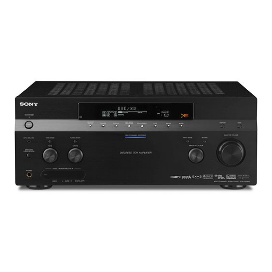
Getting Started Description and location of parts Front panel Status of the POWER button The receiver is turned off (initial setting). Press POWER to turn the receiver on. You cannot turn the receiver on using the remote. On/Standby Press /1 on the remote to turn the receiver on or set it to the standby mode. - Page 7 Name Function A POWER Press to turn the receiver on or off. B AUTO CAL MIC Connects to the supplied optimizer jack microphone for the Digital Cinema Auto Calibration function (page 43). C TONE MODE Adjusts FRONT/ CENTER/ TONE SURROUND/ SURROUND BACK BASS and TREBLE.
- Page 8 Name Function S INPUT Turn to select the input source to play back. SELECTOR T MASTER Turn to adjust the volume level of all VOLUME speakers at the same time.
-
Page 9: Rear Panel
XM jack Connects to the XM Mini Tuner and Home Dock (not supplied) (page 83). SIRIUS jack Connects to a SiriusConnect Home Tuner (not supplied) (page 83). C DMPORT Connects to a Sony DIGITAL MEDIA PORT adapter (page 21). continued... -
Page 10: Component Video Input
D COMPONENT VIDEO INPUT/ OUTPUT section Y, P Connect to a DVD IN/OUT* player, TV, or a jacks satellite tuner (page 18, 29, 30). E AUDIO INPUT/OUTPUT section AUDIO IN/ Connect to a tape OUT jacks deck or MD deck, etc (page 18, 20, 21, 24). - Page 11 Remote commander You can use the supplied remote RM-AAP018 to operate the receiver and to control the Sony audio/video components that the remote is assigned to operate (page 116). RM-AAP018 Name Function A AV ?/1 (on/ Press to turn on or off the audio/...
- Page 12 Name Function H Numeric Press to – preset/tune to preset stations. buttons – select track numbers of the CD player, DVD player, Blu- ray Disc Player or MD deck. Press 0/10 to select track number 10. – select channel numbers of the VCR or satellite tuner.
- Page 13 Name Function R DVD/ Press to display the menus of the DVD player on the TV TOP MENU, screen. Then use V/v/B/b and MENU to perform a menu operations (page 114). Press AMP (5), then press NIGHT NIGHT MODE to activate the MODE NIGHT MODE function (page 70).
-
Page 14: 1: Installing Speakers
1: Installing speakers This receiver allows you to use a 7.1 channel system (7 speakers and one sub woofer). Enjoying a 5.1/7.1 channel system To fully enjoy theater-like multi-channel surround sound requires five speakers (two front speakers, a center speaker, and two surround speakers) and a sub woofer (5.1 channel system). - Page 15 Tips • The angle A should be the same. • When you connect a 6.1 channel speaker system, place the surround back speaker behind the seating position. • Since the sub woofer does not emit highly directional signals, you can place it wherever you want.
-
Page 16: 2: Connecting Speakers
2: Connecting speakers Before connecting cords, make sure to disconnect the AC power cord (mains lead). A Monaural audio cord (not supplied) B Speaker cords (not supplied) ACenter speaker BFront speaker A (L) CFront speaker A (R) DSurround speaker (L) ESurround speaker (R) FSurround back speaker (L) GSurround back speaker (R) - Page 17 If you connect only one surround back speaker, connect it to the SURROUND BACK SPEAKERS L terminals. When you connect a sub woofer with an auto standby function, turn off the function when watching movies. If the auto standby function is set to on, it turns to standby mode automatically based on the level of the input signal to a sub woofer, then sound may not be output.
-
Page 18: 3: Connecting The Monitor
3: Connecting the monitor You can watch the selected input image when you connect the MONITOR VIDEO OUT jack to a TV. You can operate this receiver using a GUI (Graphical User Interface). Audio signals A Optical digital cord (not supplied) B Audio cord (not supplied) C Video cord (not supplied) D HDMI cable (not supplied) - Page 19 Notes • Before connecting cords, make sure to disconnect the AC power cord (mains lead). • Connect image display components such as a TV monitor or a projector to the MONITOR VIDEO OUT jack on the receiver. You may not be able to record, even if you connect recording components.
-
Page 20: 4A: Connecting The Audio Components
4a: Connecting the audio components How to hook up your components This section describes how to hook up your components to this receiver. Before you begin, refer to “Component to be connected” below for the pages which describe how to connect each component. -
Page 21: Connecting Components With Digital Audio Input/Output Jacks
Connecting components with digital audio input/output jacks The following illustration shows how to connect a Super Audio CD player, CD player, an MD deck and DIGITAL MEDIA PORT adapter. Super Audio CD player, CD player A Audio cord (not supplied) B Coaxial digital cord (not supplied) C Optical digital cord (not supplied) Notes... - Page 22 Notes on playing a Super Audio CD on a Super Audio CD player • No sound is output when playing a Super Audio CD on a Super Audio CD player connected to only the COAXIAL SA-CD/ CD IN jack on this receiver. When you play a Super Audio CD, connect the player to the MULTI CHANNEL INPUT or SA-CD/CD IN jacks.
-
Page 23: Connecting Components With Multi-Channel Output Jacks
Connecting components with multi-channel output jacks If your DVD or Super Audio CD player is equipped with multi-channel output jacks, you can connect them to the MULTI CHANNEL INPUT jacks of this receiver to enjoy multi- channel sound. Alternatively, the multi- channel input jacks can be used to connect an external multi-channel decoder. -
Page 24: Connecting Components With Analog Audio Jacks
Connecting components with analog audio jacks The following illustration shows how to connect a component with analog jacks, such as tape deck, turntable, etc. Super Audio CD player, CD player Turntable A Audio cord (not supplied) Notes • If your turntable has a ground (earth) wire, connect it to the (U) SIGNAL GND terminal. -
Page 25: 4B: Connecting The Video Components
4b: Connecting the video components How to hook up your components This section describes how to hook up your components to this receiver. Before you begin, refer to “Component to be connected” below for the pages which describe how to connect each component. - Page 26 Connecting components with HDMI jacks HDMI is the abbreviated name for High- Definition Multimedia Interface. It is an interface which transmits video and audio signals in digital format. HDMI features • A digital audio signals transmitted by HDMI can be output from the speakers connected to this receiver.
-
Page 27: Tv Monitor
DVD player Audio/video signals Audio/video signals TV monitor, projector, etc. A HDMI cable (not supplied) Satellite tuner Audio/video signals Blu-ray Disc Player, PS3™, hard disk recorder Audio/video signals continued... -
Page 28: Notes On Connecting Cables
Notes on connecting cables • We recommend that you use a Sony HDMI cable. • We recommend that you use an HDMI cable with the HDMI logo (made by Sony) for the HDMI jack corresponding to high speed (an HDMI version1.3a, category 2 cable) when... -
Page 29: Dvd Player, Blu-Ray Disc Player
Connecting a DVD player, Blu- ray Disc Player The following illustration shows how to connect a DVD player, Blu-ray Disc Player. It is not necessary to connect all the cables. Connect audio and video cords according to the jacks of your components. Audio signals A Optical digital cord (not supplied) B Coaxial digital cord (not supplied) -
Page 30: Satellite Tuner, Catv System
Connecting a satellite tuner, CATV system The following illustration shows how to connect a satellite tuner, CATV system. It is not necessary to connect all the cables. Connect audio and video cords according to the jacks of your components. Audio signals A Optical digital cord (not supplied) B Audio cord (not supplied) C Video cord (not supplied) -
Page 31: Dvd Recorder, Vcr
Connecting components with analog video and audio jack The following illustration shows how to connect a component which has analog jacks such as a DVD recorder or VCR, etc. Audio signals A Audio cord (not supplied) B Video cord (not supplied) C Audio/video cord (not supplied) It is not necessary to connect all the cables. - Page 32 Function for conversion of video signals This receiver is equipped with a function for converting video signals. You can output the video signal after connecting this receiver via the MONITOR VIDEO OUT jack as shown in the illustration. In the video input/output conversion table of the receiver OUTPUT jack HDMI OUT INPUT jack...
- Page 33 Notes on converting video signals • When video signals from a VCR, etc., are converted on this receiver and then output to your TV, depending on the status of the video signal output, the image on the TV screen may appear distorted horizontally or no image may be output.
- Page 34 In the video input/output conversion table classified by the menu settings For details on “Resolution” menu setting, see “Settings for the video (Video settings menu)” (page 57) and on operating, see “Converting analog video input signals” (page 91). “Resolution” Output from menu setting Input signals DIRECT...
-
Page 35: 5: Connecting The Antennas (Aerials)
5: Connecting the antennas (aerials) Connect the supplied AM loop antenna (aerial) and FM wire antenna (aerial). FM wire antenna (aerial) (supplied) * The shape of the connector varies depending on the area. Notes • To prevent noise pickup, keep the AM loop antenna (aerial) away from the receiver and other components. -
Page 36: 6: Preparing The Receiver And The Remote
6: Preparing the receiver and the remote Connecting the AC power cord (mains lead) Connect the AC power cord (mains lead) to a wall outlet. Notes • Before connecting the AC power cord (mains lead), make sure that metallic wires of the speaker cords are not touching each other between the SPEAKERS terminals. - Page 37 You can switch the command mode (AV SYSTEM 1 or AV SYSTEM 2) of the receiver and the remote. If both the receiver and the other Sony component respond to the same remote command, switch the command mode of either the component or the receiver to...
-
Page 38: 7: Operating The Receiver Using The Gui (Graphical User Interface)
Press CLEAR. Press 1 or 2 while the RM SET UP button is flashing. When you press 1, the command mode is set to AV SYSTEM 1. When you press 2, the command mode is set to AV SYSTEM Press ENTER when the RM SET UP button lights up. -
Page 39: Overview Of The Menus
Press SHIFT, then press MENU. The menu list of this receiver appears on the TV screen. Press AMP MENU if the menu list does not appear on the TV screen. Press V/v repeatedly to select a menu you want, then press or b. -
Page 40: Navigating Through Menus
System For details on adjusting the system using the System settings menu, see “Settings for the system (System settings menu)” (page 58). Navigating through menus RETURN/ EXIT O Make sure that the AMP button is lit. If it is not lit, or “GUI MODE” is not displayed in the display window of the receiver, follow the steps given in “Displaying the GUI menu on the TV... -
Page 41: 8: Setting The Speakers
8: Setting the speakers Setting the speaker impedances Set the appropriate speaker impedance for the speakers you are using. Make sure that the AMP button is lit. If it is not lit, or “GUI MODE” is not displayed in the display window of the receiver, follow the steps given in “7: Operating the receiver using the GUI (Graphical User Interface)”... -
Page 42: Selecting The Front Speakers
16 ohms or higher in both “A” and “B” configuration: Set “Impedance” to “8 Ω” in the Speaker settings menu. – For other types of speakers in other configurations: Set “Impedance” to “4 Ω” in the Speaker settings menu. Selecting the front speakers You can select the front speakers you want to drive. -
Page 43: 9: Calibrating The Appropriate Speaker Settings Automatically (Auto Calibration)
9: Calibrating the appropriate speaker settings automatically (Auto Calibration) The DCAC (Digital Cinema Auto Calibration) function allows you to perform automatic calibration, such as checking the connection between each speaker and the receiver, adjusting the speaker level, and measuring the distance of each speaker from your seating position automatically. -
Page 44: Performing Auto Calibration
On setting up the active sub woofer • When a sub woofer is connected, turn on the sub woofer and turn up the volume beforehand. Turn the MASTER VOLUME knob to just before the mid-point. • If you connect a sub woofer with the crossover frequency function, set the value to maximum. - Page 45 Press V/v repeatedly to select “Settings,” then press The Settings menu list appears on the TV screen. Press V/v repeatedly to select “Auto Calibration,” then press or b. Press V/v repeatedly to select “Quick Setup,” then press Press V/v repeatedly and un-check the items you do not want to measure.
- Page 46 Makes the measurement of frequency from each speaker flat. Engineer Sets the frequency to one that matches that of the Sony listening room standard. Front Reference Adjusts the characteristics of all the speakers to match the characteristics of the front speaker.
- Page 47 Notes • After reflecting the results of a compensation for a frequency characteristic, signals with a sampling frequency of more than 96 kHz are always played back at either 44.1 kHz or 48 kHz. • The frequency response measurement result is not utilized in the following cases.
- Page 48 Message list after auto calibration measurement Display Explanation Code 30 Headphones are connected. Remove the headphones and perform the auto calibration again. Code 31 SPEAKERS (OFF/A/B/A+B) is set to OFF. Set it to others and re-perform the measurement. Code 32 None of the speakers were detected.
- Page 49 To set auto calibration items more precisely (Enhanced Setup) On the Auto Calibration menu, select “Enhanced Setup,” then press • Seating Position You can register three patterns as position 1, 2, and 3, depending on the seating position, listening environment, and measurement conditions.
-
Page 50: Playback
Playback Selecting a component MUTING Press one of the input buttons. When you want to select a component connected to the PHONO, the MULTI CHANNEL INPUT or TV jack, or satellite radio, press SHIFT and then press PHONO, MULTI IN or TV, SIRIUS or XM. - Page 51 Tips • You can adjust the volume differently depending on the speed with which you turn the MASTER VOLUME knob. To turn the volume up or down quickly: turn the knob quickly. To make fine adjustment: turn the knob slowly. •...
-
Page 52: Listening To A Super Audio Cd/Cd
Listening to a Super Audio CD/CD • The operation is described for a Sony Super Audio CD player. • Refer to the operating instructions supplied with the Super Audio CD player or CD player. You can select the sound field to suit the music. -
Page 53: Watching A Dvd/Blu-Ray Disc
Watching a DVD/Blu-ray Disc • Refer to the operating instructions supplied with the TV and DVD player, Blu-ray Disc Player. Select the sound format of the disc to be played, if necessary. You can select the sound field to suit the movie or the music. Refer to page 64 for details. -
Page 54: Enjoying Video Games
Enjoying video games • Refer to the operating instructions supplied with the TV and video game. VIDEO 3 IN/PORTABLE AV IN Turn on the TV and video game. Turn on the receiver. Press INPUT SELECTOR to select “VIDEO 3*.” You can also use INPUT SELECTOR on this receiver to select “VIDEO 3*.”... -
Page 55: Watching Video
Watching video • Refer to the operating instructions supplied with the TV and VCR. Turn on the VCR. Turn on the receiver. Press INPUT SELECTOR to select “VIDEO 1*.” You can also use INPUT SELECTOR on this receiver to select “VIDEO 1*.” * When you connect VCR to the VIDEO 1 jack. -
Page 56: Amplifier Operations
Amplifier Operations Settings for the audio (Audio settings menu) You can use the Audio settings menu to make settings for the audio to suit your preference. Select “Audio” in the Settings menu. For details on adjusting the parameters, see “7: Operating the receiver using the GUI (Graphical User Interface)”... -
Page 57: Settings For The Video (Video Settings Menu)
Settings for the video (Video settings menu) You can use the Video settings menu to make settings for video. Select “Video” in the Settings menu. For details on adjusting the parameters, see “7: Operating the receiver using the GUI (Graphical User Interface)” (page 38). -
Page 58: Settings For The System (System Settings Menu)
connected to the receiver. The multi-channel sound can be played back as it is. Note Audio signals are not output from the TV’s speakers when HDMI Audio is set to “AMP.” x HDMI SW Level Lets you set the level of the sub woofer to 0 dB or +10 dB when PCM signals are input via an HDMI connection. -
Page 59: Enjoying Surround Sound
Enjoying Surround Sound Enjoying a pre- programmed sound field Start playing a sound source you want to listen to (CD, DVD, etc.). Make sure that the AMP button is lit. If it is not lit, or “GUI MODE” is not displayed in the display window of the receiver, follow the steps given in “7: Operating the receiver using the GUI... - Page 60 x 2ch Analog Direct You can switch the audio of the selected input to 2 channel analog input. This function enables you to enjoy high quality analog sources. When using this function, only the volume and front speaker balance can be adjusted. When connecting Blu-ray Disc Players and other next generation HD players This receiver supports the following audio formats.
- Page 61 Audio format DTS-HD a) b) Master Audio Multi channel Linear PCM a)Audio signals are output in another format if the playback component does not correspond to the format. For details, refer to the operating instructions of the playback component. b)Signals with a sampling frequency of more than 96 kHz are played back at 96 kHz or 88.2 kHz. Connection of the playback component and Maximum number of channels...
- Page 62 Types of A.F.D. mode The Auto Format Direct (A.F.D.) mode allows you to listen to higher fidelity sound and select the decoding mode for listening to a 2 channel stereo sound as multi-channel sound. A.F.D. mode A.F.D. Auto ProLogic PLII Movie PLII Music PLII Game PLIIx Movie*...
- Page 63 Notes • This function does not work in the following cases. – The multi-channel input is selected. – DTS-HD signals with a sampling frequency of more than 48 kHz are being received. – Dolby TrueHD signals with a sampling frequency of more than 96 kHz are being received.
- Page 64 Stadium Sports Portable Audio Effect Reproduces the sound characteristics of the Sony Pictures Entertainment “Cary Grant Theater” cinema production studio. This is a standard mode, great for watching almost any type of movie. Reproduces the sound characteristics of the Sony Pictures Entertainment “Kim Novak Theater”...
- Page 65 Sound field Sound field Headphone* Headphone (2ch) Headphone Theater DCS This mode is selected automatically when you use headphones Headphone (Direct) Headphone (Multi) * You can select this sound field mode if the headphones are connected to the receiver. Notes •...
-
Page 66: Adjusting The Sound Effect
Adjusting the sound effect Parameter that allows custom settings provides a “Custom Settings” menu that can be used to make advanced adjustments. Choose the sound field (page 59). Press b to select “Custom Settings,” then press While monitoring the sound, adjust the selected parameter using V/v and For details, see following menu... - Page 67 x Dimension Control Lets you perform further adjustments for Dolby Pro Logic II and IIx Music mode decoding. You can set this parameter only when A.F.D. mode is set to “PLII Music” or “PLIIx Music.” You can adjust the difference between the front channels and the surround channels.
-
Page 68: Using The Surround Back Decoding Mode
Using the surround back decoding mode By decoding the surround back signal recorded in Dolby Digital Surround EX, DTS- ES Matrix, DTS-ES Discrete 6.1, etc., format, you can enjoy the surround sound intended by the filmmakers. Make sure that the AMP button is lit. - Page 69 Input stream Output Surround back channels decoding DTS 5.1 — DTS-ES Matrix DTS Matrix decoding DTS-ES DTS Discrete Discrete 6.1 decoding A 6.1 channel decode flag is information recorded in software, such as DVDs. A Dolby Digital DVD that includes a Surround EX flag.
-
Page 70: Enjoying The Surround Effect At Low Volume Levels (Night Mode)
Enjoying the surround effect at low volume levels (NIGHT MODE) This function allows you to retain a theater like environment at low volume levels. This function can be used with other sound fields. When watching a movie late at night, you will be able to hear the dialog clearly even at a low volume level. -
Page 71: Advanced Speakers Setting Up
Advanced Speakers Setting Up Adjusting the speaker settings manually You can adjust the each speaker manually. You can also adjust the speaker levels after the auto calibration is completed. Making settings with the Manual Setup menu Make sure that the AMP button is lit. - Page 72 will be output from the sub woofer if the digital input signal contains L.F.E. signals, or if the front or surround speakers are set to “SMALL,” the sound field for movie is selected, or “Portable Audio” is selected. x Distance (Distance from the seating position to each speaker) You can adjust the distance from the seating...
- Page 73 • SIDE/LOW Select if the location of your surround speakers corresponds to sections A and C. • SIDE/HIGH Select if the location of your surround speakers corresponds to sections A and D. • BEHD/LOW Select if the location of your surround speakers corresponds to sections B and C.
- Page 74 Make sure that the AMP button is lit. If it is not lit, or “GUI MODE” is not displayed in the display window of the receiver, follow the steps given in “7: Operating the receiver using the GUI (Graphical User Interface)” (page 38). Press V/v repeatedly to select “Settings,”...
- Page 75 You can select the test tone type. Select the speaker you want to adjust, then press The test tone is output from each speaker in sequence. Adjust the parameter using V/v, then press Tips • To adjust the level of all speakers at the same time, press MASTER VOL +/–.
-
Page 76: Speaker Settings
Other menu parameters of Speaker settings x Sur Back Assign (Settings of the surround back speaker(s)) • OFF If you have not connected surround back speakers, select “OFF.” • BI-AMP If you connect front speakers in a bi- amplifier configuration, select “BI-AMP.” Note Set “Sur Back Assign”... -
Page 77: Adjusting The Equalizer
Adjusting the equalizer You can use following parameters to adjust the tonal quality (bass/treble level) of all speakers, store up to 5 different equalizer settings, and apply them. These settings are applied to all sound fields and for each speaker. Bass Level (dB) -
Page 78: Clearing Stored Equalizer Settings
Press V/v repeatedly to select the preset number that you want to register as the number to store the equalizer adjustment, then press The equalizer adjustment screen appears on the TV screen. Choose the speaker you want to adjust using B/b, then press Press B/b repeatedly to select “Bass”... -
Page 79: Tuner Operations
Tuner Operations Listening to FM/AM radio You can listen to FM and AM broadcasts through the built-in tuner. Before operation, make sure you have connected the FM and AM antennas (aerials) to the receiver (page 35). The tuning scale for direct tuning is shown below. •... -
Page 80: Direct Tuning
Direct tuning Enter the frequency of a station directly by using the numeric buttons. Make sure that the AMP button is lit. If it is not lit, or “GUI MODE” is not displayed in the display window of the receiver, follow the steps given in “7: Operating the receiver using the GUI (Graphical User Interface)”... -
Page 81: Presetting Radio Stations
Presetting radio stations You can preset up to 30 FM and 30 AM stations. Then you can easily tune in the stations you often listen to. Make sure that the AMP button is lit. If it is not lit, or “GUI MODE” is not displayed in the display window of the receiver, follow the steps given in “7: Operating the receiver using the GUI... -
Page 82: Listening To Satellite Radio
Listening to satellite radio ABOUT XM RADIO XM offers over 170 digital radio channels: the most commercial-free music channels, premier news, sports, talk, and traffic and weather in 21 metro markets. XM’s on-air hosts broadcast live from studios in Washington, D.C., New York City and Nashville. - Page 83 Connecting the XM Radio or SIRIUS Satellite Radio SIRIUS jack To connect to the XM jack Before operating the system, connect the XM Mini Tuner and Home Dock to the XM jack. Note To ensure optimal reception of XM’s satellite signal, move your antenna to various window locations around your home to see where the best reception will be received.
- Page 84 SIRIUS Press OPTIONS, then press V/v repeatedly to select “Radio ID” or “Sirius ID,” then press SIRIUS Check the XM Radio ID or Sirius ID on the TV screen and write it in the space provided here. XM Radio ID:_____________________ Sirius ID:_________________________ You can also check the XM Radio ID and Sirius ID using the display on the...
- Page 85 Make sure that the AMP button is lit. If it is not lit, or “GUI MODE” is not displayed in the display window of the receiver, follow the steps given in “7: Operating the receiver using the GUI (Graphical User Interface)” (page 38). Press V/v repeatedly to select “XM”...
- Page 86 Press the numeric buttons to enter the channel number. Press The selected channel is tune in. Presetting the channels You can select the channels you want directly by presetting them using the preset numbers. You can preset up to 30 XM Radio channels and 30 SIRIUS Satellite Radio channels.
- Page 87 Restricting access to specific channels (Parental Lock) (SIRIUS only) You can restrict access to certain channels using your own lock code. The lock code is set to “0000” as the default. Change the lock code before you use this function for the first time (see “To change the lock code”).
-
Page 88: To Listen To The Locked Channels
To change the lock code Press V/v repeatedly to select “SIRIUS,” then press Press OPTIONS, then press V/v to select “Lock Code,” then press “Enter your 4-digit lock code.” appears. Enter your 4-digit lock code using the number buttons. “Enter a new lock code.” appears. Enter a new 4-digit lock code using the number buttons. - Page 89 XM Radio message list Message Explanation appears Check Antenna The XM antenna is not connected or transmission is not being received properly. Updating The encryption code is being updated. Wait until the encryption code has been updated. No Signal The signal is too weak. Loading The audio channel or information is being acquired.
- Page 90 Message Explanation appears Firmware The SiriusConnect HomeTuner Updating firmware is being updated. ––––– There is no text information in the channel. Remedies — This is not an error. The text information may not be displayed depending on the system condition, for example, right after the system has received a channel.
-
Page 91: Other Operations
For details on connecting the DIGITAL MEDIA PORT adapter, see “Connecting components with digital audio input/output jacks” (page 21). Sony offers the following DIGITAL MEDIA PORT adapters: • TDM-BT1 Bluetooth™ Wireless Audio Adapter • TDM-NW1 DIGITAL MEDIA PORT Adapter •... - Page 92 Selecting an operation screen to operate the component connected to the DIGITAL MEDIA PORT adapter You can select an operation screen using the GUI menu, depending on the DIGITAL MEDIA PORT adapter you want to use. For some adapter, such as TDM-BT1 or TDM- NW1, the operation screen is fixed and you cannot change it on the GUI screen.
- Page 93 Operating the component connected to the DIGITAL MEDIA PORT adapter To operate the TDM-iP1 or TDM- NC1 using the GUI menu of the receiver Make sure that “System GUI” is selected in step 6 in “Selecting an operation screen to operate the component connected to the DIGITAL MEDIA PORT adapter”...
- Page 94 Do the following Play Press H. Pause Press X. To resume play, press the button again. Stop Press x.* Find the beginning of a Press .. track during playback, or find the beginning of the previous track Find the beginning of the Press >.
-
Page 95: Naming Inputs
Naming inputs You can enter a name of up to 8 characters for inputs and display it. This is convenient for labeling the jacks with the names of the connected components. Choose the item you want to name. You can name the following items. •... -
Page 96: Switching Between Digital And Analog Audio (Input Mode)
Switching between digital and analog audio (INPUT MODE) When you connect components to both digital and analog audio input jacks on the receiver, you can fix the audio input mode to either of them, or switch from one to the other, depending on the type of material you intend to watch. -
Page 97: Enjoying The Sound/Images From Other Inputs
Enjoying the sound/ images from other inputs You can reassign video and/or audio signals to another input. Example) Connect the OPTICAL OUT jack of the DVD player to the OPTICAL VIDEO 1 IN jack of this receiver when you want to input the only digital optical audio signals from the DVD player. - Page 98 Input name Assignable video Video1 Component input jacks Video1 Composite Video2 Composite Video3 Composite DVD/BD Component DVD/BD Composite SAT/CATV Component SAT/CATV Composite HDMI1 HDMI2 HDMI3 Assignable audio Video1 OPT input jacks Video3 OPT SAT/CATV OPT MD/Tape OPT Video2 COAX DVD/BD COAX SA-CD/CD COAX Notes •...
-
Page 99: Changing The Display
Changing the display You can check the sound field, etc., by changing the information on the display. SHIFT DISPLAY MENU Press DISPLAY repeatedly. Each time you press DISPLAY, the display will change as follows. Input name you selected t Original input name t Sound field type t Volume... - Page 100 About the indicators on the display Name Function A SW Lights up when sub woofer is connected and the audio signal is output from the SUB WOOFER jack. While this indicator lights up, the receiver creates a sub woofer signal based on the L.F.E.
- Page 101 Name Function D INPUT Lights up constantly. One of the input indicators also lights up according to the current input. E AUTO Lights up when INPUT MODE is set to “Auto.” F HDMI Lights up when the receiver recognizes a component connected via an HDMI IN jack.
- Page 102 Name Function W ;PRO Lights up when the receiver LOGIC (II/ applies Dolby Pro Logic IIx) processing to 2 channel signals in order to output the center and surround channel signals. “;PRO LOGIC II” also lights up when the Dolby Pro Logic II Movie/Music/Game decoder is activated.
-
Page 103: Using The Sleep Timer
Using the sleep timer You can set the receiver to turn off automatically at a specified time. SLEEP Press SLEEP repeatedly. Each time you press SLEEP, the display changes cyclically as follows: When sleep timer is being used, “SLEEP” lights up. To check the remaining time before the receiver turns off, press SLEEP. -
Page 104: Using A Bi-Amplifier Connection
Notes • Sound adjustments do not affect the signal output from the MD/TAPE OUT jacks. • The audio input signals from the MULTI CHANNEL INPUT jacks are not output. To record digital sound Connect a component for playback to the digital audio input (OPTICAL IN) jack, and connect the recording component to the OPTICAL MD/TAPE OUT jack. -
Page 105: Operating Without Connecting To The Tv
Notes • You cannot use the FRONT SPEAKERS B jacks for a bi-amplifier connection. • When you use the auto calibration function, make the bi-amplifier settings before you perform auto calibration. • If you make the bi-amplifier settings, the speaker level, balance, and equalizer settings of the surround back speakers become invalid, and those of the front speakers are used. - Page 106 Overview of the menus The following options are available in each menu. For details on navigating through menus, see page 40. Menu Item Auto Calibration AUTO CAL START? COMPLETE [xxxxxxxxxx] WARNING CODE [xxx:4x] FL, FR, C, SL, SR, SBL, SBR : 0, 1, 2, 3 ERROR CODE [xxx:3x] CAL TYPE [xxxxxxxxx] FULL FLAT, ENGINEER, FRONT POSITION [xxxxxxxx]...
- Page 107 Menu Item Speaker Settings SP PATTERN [xxxxx] SUB WOOFER [xxx] FRONT SP [xxxxx] CENTER SP [xxxxx] SURROUND SP [xxxxx] SUR BACK SP [xxxxxx] BI-AMP [xxx] FRONT L [xxxxxxxxx] FRONT R [xxxxxxxxx] CENTER [xxxxxxxxx] SURROUND L [xxxxxxxxx] SURROUND R [xxxxxxxxx] SUR BACK [xxxxxxxxx] 3’ 3” to 32’ 9” (1 inch step) SUR BACK L [xxxxxxxxx] SUR BACK R...
- Page 108 Menu Item Sur Settings SOUND FIELD SELECT ? SB DECODING [xxxx] SB DEC MODE [xxxxxxx] DDEX, PLIIx MV, PLIIx MS EFFECT LEVEL [xxx%] CENTER WIDTH [x] DIMENSION [xxxxxxx] PANORAMA MODE [xxx] SCREEN DEPTH [xxx] VIR. SPEAKERS [xxx] FRONT REVERB [xxx] EQ Settings EQ PRESET [xxx] FRONT BASS [xxx dB]...
- Page 109 Menu Item Audio Settings A/V SYNC [xxxms] DUAL MONO [xxxxxxxx] MAIN/SUB, MAIN, SUB, MAIN+SUB MAIN DEC. PRIORITY [xxxx] DIGITAL ASSIGN ? VIDEO1 OPT c [xxxxxx] NONE, VIDEO1 to 3, DVD/BD, SAT, VIDEO2 COAX c [xxxxxx] VIDEO3 OPT c [xxxxxx] DVD/BD COAX c [xxxxxx] SAT OPT c [xxxxxx] MD/TAPE OPT c...
- Page 110 Performing auto calibration For details on the auto calibration, see “9: Calibrating the appropriate speaker settings automatically (Auto Calibration)” (page 43). Refer to “Before you perform the auto calibration” (page 43) before performing the auto calibration. To operate on the receiver Press SHIFT, then press MENU to switch from “GUI MODE”...
- Page 111 Makes the measurement of frequency from each speaker flat. ENGINEER Sets the frequency characteristics to a set that matches that of the Sony listening room standard. FRONT REF Adjusts the characteristics of all the speakers to match the characteristics of the front speaker.
-
Page 112: Tuning Radio Stations
Tuning radio stations Press TUNER repeatedly to select the FM or AM band. You can also use INPUT SELECTOR on the receiver. Press TUNING + or TUNING –. Press TUNING + to scan from low to high frequencies, press TUNING – to scan from high to low frequencies. -
Page 113: Selecting A Preset Channel
Selecting channels from a category (CATEGORY TUNING) Press SHIFT, then press XM to select “XM RADIO,” or press SIRIUS to select “SIRIUS.” You can also use INPUT SELECTOR on the receiver. Press CATEGORY MODE repeatedly to select “ONE CATEGORY.” • All Categories: You can select a channel from all the categories. -
Page 114: Using The Remote
When you program the remote to control the following Sony or non-Sony components, you can use the buttons on the remote that are marked with circles. Note, however, that some buttons may not operate your component. - Page 115 Table of buttons used to control each component TV VCR Blu-ray Component player, Disc DVD/ Player combo Button AV ?/1, ?/1 (after pressing TV) Numeric buttons MEMORY/ENTER CLEAR/D.TUNING/ >10/-/-- DISPLAY OPTIONS/TOOLS RETURN/EXIT V/v/B/b MENU ./> CATEGORY +/–, B·/·b m/TUNING –, M/TUNING + X, x DISC SKIP...
-
Page 116: Programming The Remote
The procedure below uses as an example a case in which a VCR made by a company other than Sony is connected to the VIDEO 2 IN jacks on the receiver. Before you begin, note that: –... - Page 117 742, 743, 744, 745 SANYO 717, 720, 746 SHARP 748, 749 TELEFUNKEN 751, 752 TOSHIBA 747, 756 ZENITH * If an AIWA VCR does not work even though you enter the code for AIWA, enter the code for Sony instead. continued...
- Page 118 To control a DVD player Maker Code(s) SONY 401, 402 BROKSONIC DENON HITACHI 415, 423 MITSUBISHI ORITRON PANASONIC 406, 408, 425 PHILIPS PIONEER 409, 410 SAMSUNG 416, 422 TOSHIBA 404, 421 ZENITH 418, 420 To control a DVD recorder Maker...
-
Page 119: Clearing All The Contents Of The Remote's Memory
HUGHES JVC/Echostar/Dish Network MITSUBISHI SAMSUNG TOSHIBA 869, 870 To control a cable box Maker Code(s) SONY 821, 822, 823 HAMLIN/REGAL 836, 837, 838, 839, 840 JERROLD/G.I./ 806, 807, 808, 809, 810, MOTOROLA 811, 812, 813, 814, 819 JERROLD 830, 831... -
Page 120: Additional Information
Digital Cinema Sound (DCS) Unique sound reproduction technology for home theater developed by Sony, in cooperation with Sony Pictures Entertainment, for enjoying the exciting and powerful sound of movie theaters at home. With this “Digital Cinema Sound”... - Page 121 x Dolby Digital Digital audio encoding/decoding technology developed by Dolby Laboratories, Inc. It consists of front (left/right), center, surround (left/right) and sub woofer channels. It is a designated audio standard for DVD-video and also known as 5.1 channels surround. x Dolby Digital Plus Dolby Digital Plus provides the flexibility and efficiency to deliver more channels of compelling surround sound for high-definition...
- Page 122 “p” of “480p” stands for “Progressive.” x x.v.Color x.v.Color is a more familiar term for the xvYCC standard proposed by Sony, and is a trademark of Sony. xvYCC is an international standard for color space in video. This standard can express a wider color range...
-
Page 123: Precautions
Do not use any type of abrasive pad, scouring powder, or solvent, such as alcohol or benzine. If you have any questions or problems concerning your receiver, please consult your nearest Sony dealer. -
Page 124: Troubleshooting
If you experience any of the following difficulties while using the receiver, use this troubleshooting guide to help you remedy the problem. Should any problem persist, consult your nearest Sony dealer. Audio There is no sound, no matter which component is selected, or only a very low-level sound is heard. - Page 125 The source sound input from the HDMI jack is not output from an amplifier or the TV speaker connected to the receiver. • Check that the component is connected correctly to the HDMI jack for that component. • The sound is not output when you display the receiver’s menu on the TV monitor.
- Page 126 Recording cannot be carried out. • Check that the components are connected correctly (page 20). • Select the source component using INPUT SELECTOR (page 50). The MULTI CHANNEL DECODING lamp does not light up in blue. • Check that the playback component is connected on a digital jack and the input is selected properly on this receiver.
-
Page 127: Remote Control
• Make sure you select the correct input on To ground the remote. • When you operate a programmed non- Sony component, the remote may not function properly depending on the model and the maker of the component. Error messages If there is a malfunction, the display shows a code of two numbers and a message. -
Page 128: Specifications
Reference sections for clearing the memory To clear All memorized settings Specifications AUDIO POWER page 36 SPECIFICATIONS POWER OUTPUT AND TOTAL HARMONIC DISTORTION: With 8 ohm loads, both channels driven, from 20 – 20,000 Hz; rated 100 watts per channel minimum RMS power, with no more than 0.09% total harmonic distortion from 250 milliwatts to rated output. - Page 129 Frequency response PHONO RIAA equalization curve ± 0.5 dB MULTI CHANNEL 10 Hz – 100 kHz INPUT, SA-CD/CD, ± 3 dB MD/TAPE, DVD/BD, TV, SAT/CATV, VIDEO 1/2/3 Inputs (Analog) PHONO Sensitivity: 2.5 mV Impedance: 50 kohms S/N: 90dB (A, 20 kHz LPF) MULTI CHANNEL Sensitivity: 150 mV...
- Page 130 General Power requirements 120 V AC, 60 Hz Power output (DIGITAL MEDIA PORT) DC OUT: 5 V, 700 mA Power consumption 350 W Power consumption (during standby mode) 0.7 W (when “HDMI Control” is set to “OFF”) Dimensions 430 × 175 × 430 mm (width/height/depth) including projecting parts and controls...
-
Page 131: Index
Index Symbols U SIGNAL GND terminal 24 Numerics 2 channel 59 2ch Analog Direct 60 2ch Stereo Mode 59 4 Ω 41 5.1 channel 14 7.1 channel 14 8 Ω 41 A.F.D. (mode) 62 A/V Sync 56 AC power cord 36 AM 79 Audio (Settings) 56 Auto Calibration 43... - Page 132 HDMI (Settings) 57 HDMI Audio 57 HDMI button 7 HDMI Control 57 HDMI jacks 9 HDMI SW Level 58 Headphone (Settings) 65 Input 50 Input Assign 97 INPUT MODE 96 INPUT SELECTOR 52 iPod 92 L.F.E. (Low Frequency Effect) 101 LARGE 72 Level 71 List Mode 94...
- Page 133 Test Tone 74 TONE 7 TONE MODE 7 Treble 7 Tuner 79 Tuner (Settings) 108 Tuning 79 Up converting 32 VCR 55 Video (Settings) 57 VIDEO 3 IN/PORTABLE AV IN jacks 31 Video game 54 Virtual Speakers 67 XM Radio 82...