
Related Manuals for Sony STR-DA1200ES


Summary of Contents for Sony STR-DA1200ES
- Page 1 2-694-840-12(2) Multi Channel AV Receiver Operating Instructions STR-DA1200ES Sony Corporation ©2006 Sony Corporation Printed in Malaysia...
- Page 2 Never use the plug without the fuse cover. If you should lose the fuse cover, please contact your nearest Sony service station. For customers in Europe Disposal of Old Electrical & Electronic Equipment (Applicable in the European...
-
Page 3: About This Manual
About This Manual • The instructions in this manual are for model STR- DA1200ES. Check your model number by looking at the lower right corner of the front panel. • The instructions in this manual describe the controls on the supplied remote. You can also use the controls on the receiver if they have the same or similar names as those on the remote. -
Page 4: Table Of Contents
Table of Contents Getting Started Description and location of parts ...6 1: Installing speakers ...16 2: Connecting speakers ...17 3a: Connecting the audio components ...19 3b: Connecting the video components ...24 4: Connecting the antennas (aerials) ...35 5: Preparing the receiver and the remote ...36 6: Setting the speakers ...38 7: Calibrating the appropriate settings automatically... - Page 5 Watching component images from other inputs (COMPONENT VIDEO ASSIGN) ... 88 Changing the display ... 89 Using the Sleep Timer ... 90 Recording using the receiver ... 90 Using a bi-amplifier connection ... 91 Using the Remote Operating each component using the remote ...
-
Page 6: Getting Started
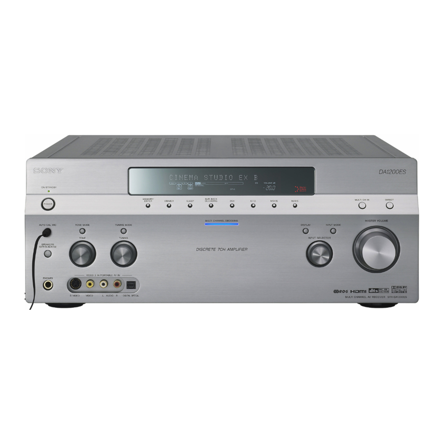
Getting Started Description and location of parts Front panel To remove the cover Press PUSH. When you remove the cover, keep it out of reach from children. Name Function A POWER Press to turn the receiver on or off (page 36, 48, 49, 50, 51, 76). - Page 7 Name Function C TONE MODE Adjusts FRONT BASS and FRONT TREBLE. TONE Press TONE MODE repeatedly to select BASS or TREBLE, then turn TONE to adjust the level (page 57). D MEMORY/ Press to operate a tuner ENTER (FM/AM) (page 77). TUNING MODE TUNING E Remote sensor Receives signals from...
- Page 8 About the indicators on the display Name Function A SW Lights up when sub woofer selection is set to “YES” and the audio signal is output from the SUB WOOFER jack (page 63). While this indicator lights up, the receiver creates a sub woofer signal based on the L.F.E.
- Page 9 Name Function C ;DIGITAL Lights up when the receiver (EX) is decoding Dolby Digital Surround signals. “;DIGITAL EX” also lights up when the receiver is decoding Dolby Digital Surround EX signals. When playing a Dolby Digital format disc, be sure that you have made digital connections and that INPUT MODE is not set to...
- Page 10 Name Function R L.F.E. Lights up when the disc being played back contains an L.F.E. (Low Frequency Effect) channel and the L.F.E. channel signal is actually being reproduced, the bars underneath the letters light up to indicate the level. Since the L.F.E. signal is not recorded in all parts of the input signal the bar indication will fluctuate...
-
Page 11: Rear Panel
Rear panel A DIGITAL INPUT/OUTPUT section OPTICAL IN/ Connects to a DVD OUT jacks player, Super Audio CD player, etc. The COAXIAL jack provides a better COAXIAL IN quality sound (page jacks 19, 20, 29). HDMI IN/ Connects to a DVD MONITOR player, or a satellite OUT jacks... - Page 12 E VIDEO/AUDIO INPUT/OUTPUT section AUDIO IN/ OUT jacks VIDEO IN/ OUT jacks* S VIDEO IN/ OUT jacks* F SPEAKERS section * You can watch the selected input image when you connect the MONITOR OUT jack to a TV (page 27). You can also display certain menu settings and the sound field on the monitor when you press ON SCREEN on the remote (page 83).
- Page 13 Remote commander You can use the supplied remote RM-AAP015 to operate the receiver and to control the Sony audio/video components that the remote is assigned to operate (page 94). RM-AAP015 Name Function A AV ?/1 Press to turn on or off the audio/...
- Page 14 Name Function H Numeric Press to buttons – preset/tune to preset stations. – select track numbers of the CD player, DVD player or MD deck. Press 0/10 to select track number 10. – select channel numbers of the VCR or satellite tuner. –...
- Page 15 Name Function X CLEAR Press to – clear a mistake when you press the incorrect numeric button. – return to continuous playback, etc. of the satellite tuner or DVD player. >10 Press to select – track numbers over 10 of the VCR, satellite tuner, CD player or MD deck.
-
Page 16: 1: Installing Speakers
1: Installing speakers This receiver allows you to use a 7.1 channel system (7 speakers and one sub woofer). Enjoying a 5.1/7.1 channel system To fully enjoy theater-like multi-channel surround sound requires five speakers (two front speakers, a center speaker, and two surround speakers) and a sub woofer (5.1 channel system). -
Page 17: 2: Connecting Speakers
2: Connecting speakers A Monaural audio cord (not supplied) B Speaker cords (not supplied) AFront speaker A (L) BFront speaker A (R) CCenter speaker DSurround speaker (L) ESurround speaker (R) FSurround back speaker (L) GSurround back speaker (R) HSub woofer If you have an additional front speaker system, connect them to the FRONT SPEAKERS B terminals. - Page 18 When you connect a sub woofer with an auto standby function, turn off the function when watching movies. If the auto standby function is set to on, it turns to standby mode automatically based on the level of the input signal to a sub woofer, then sound may not be output.
-
Page 19: 3A: Connecting The Audio Components
3a: Connecting the audio components How to hook up your components This section describes how to hook up your components to this receiver. Before you begin, refer to “Component to be connected” below for the pages which describe how to connect each component. - Page 20 Connecting components with digital audio input/output jacks The following illustration shows how to connect a Super Audio CD player, CD player and an MD/TAPE deck. Super Audio CD player, CD player A Audio cord (not supplied) B Coaxial digital cord (not supplied) C Optical digital cord (not supplied) MD deck, TAPE deck...
- Page 21 Notes on playing a Super Audio CD on a Super Audio CD player • No sound is output when playing a Super Audio CD on a Super Audio CD player connected to only the COAXIAL SA-CD/ CD IN jacks on this receiver. When you play a Super Audio CD, connect the player to the MULTI CHANNEL INPUT or SA-CD/CD IN jacks.
-
Page 22: Connecting Components With
Connecting components with multi-channel output jacks If your DVD or Super Audio CD player is equipped with multi-channel output jacks, you can connect it to the MULTI CHANNEL INPUT jacks of this receiver to enjoy multi- channel sound. Alternatively, the multi- channel input jacks can be used to connect an external multi-channel decoder. - Page 23 Connecting components with analog audio jacks The following illustration shows how to connect a component with analog jacks, such as tape deck, turntable, etc. Super Audio CD player, CD player Turntable A Audio cord (not supplied) Note If your turntable has a ground (earth) wire, connect it to the (U) SIGNAL GND terminal.
-
Page 24: 3B: Connecting The Video Components
3b: Connecting the video components How to hook up your components This section describes how to hook up your components to this receiver. Before you begin, refer to “Component to be connected” below for the pages which describe how to connect each component. -
Page 25: Connecting Components With Hdmi Jacks
DVD player Audio Audio/video signals signals A HDMI cable (not supplied) We recommend that you use a Sony HDMI cable. B Coaxial digital cord (not supplied) C Optical digital cord (not supplied) Satellite tuner/TV monitor, projector, etc. Audio Audio/video signals... - Page 26 VIDEO OUT jacks, S VIDEO OUT jacks, or MONITOR OUT jacks. • Use an HDMI cable with the HDMI logo (made by Sony). • Check the setup of the connected component if an image is poor or the sound does not come out of a component connected via the HDMI cable.
-
Page 27: Tv Monitor
Connecting a TV monitor The image from a visual component connected to this receiver and the menu of this receiver can be displayed on a TV screen. It is not necessary to connect all the cables. Connect audio and video cords according to the jacks of your components. - Page 28 Notes • Connect image display components such as a TV monitor or a projector to the MONITOR OUT jack on the receiver. You may not be able to record, even if you connect recording components. • Turn on the receiver when the video and audio of a playback component are being output to a TV via the receiver.
-
Page 29: Dvd Player, Dvd Recorder
Connecting a DVD player/DVD recorder The following illustration shows how to connect a DVD player/DVD recorder. It is not necessary to connect all the cables. Connect audio and video cords according to the jacks of your components. Connecting a DVD player Audio signals A Coaxial digital cord (not supplied) B Audio cord (not supplied) -
Page 30: Connecting A Dvd Recorder
Connecting a DVD recorder DVD recorder Audio signals Video signals A Optical digital cord (not supplied) B Audio cord (not supplied) C Video cord (not supplied) D S video cord (not supplied) -
Page 31: Satellite Tuner
Connecting a satellite tuner The following illustration shows how to connect a satellite tuner. It is not necessary to connect all the cables. Connect audio and video cords according to the jacks of your components. Audio signals A Optical digital cord (not supplied) B Audio cord (not supplied) C Component video cord (not supplied) D S video cord (not supplied) -
Page 32: Vcr
Connecting components with analog video and audio jack The following illustration shows how to connect a component which has analog jacks such as a VCR, etc. Audio signals A Audio cord (not supplied) B Video cord (not supplied) It is not necessary to connect all the cables. Connect audio and video cords according to the jacks of your components. - Page 33 Function for conversion of video signals This receiver is equipped with a function for converting video signals. You can output the video signal after connecting this receiver via the MONITOR OUT jack as shown in the illustration. In the video input/output conversion table of the receiver Input Signals OUTPUT jack HDMI OUT...
- Page 34 Notes on converting video signals • You cannot down-convert input signals using the receiver. Component video signals cannot be converted to S video signals and composite video signals. S video signals cannot be converted to composite video signals. HDMI video signals cannot be converted to component video signals, S video signals, and video signals.
-
Page 35: 4: Connecting The Antennas (Aerials)
4: Connecting the antennas (aerials) Connect the supplied AM loop antenna (aerial) and FM wire antenna (aerial). * The shape of the connector varies depending on the area. Notes • To prevent noise pickup, keep the AM loop antenna (aerial) away from the receiver and other components. -
Page 36: 5: Preparing The Receiver And The Remote
5: Preparing the receiver and the remote Connecting the AC power cord (mains lead) Connect the supplied AC power cord (mains lead) to the AC IN terminal on the receiver, then connect the AC power cord (mains lead) to a wall outlet. AC OUTLET* To the wall outlet * The configuration, shape, number of AC outlets,... - Page 37 You can switch the command mode (AV SYSTEM 1 or AV SYSTEM 2) of the receiver and the remote. If both the receiver and the other Sony component respond to the same remote command, switch the command mode of either the component or the receiver to...
-
Page 38: 6: Setting The Speakers
To switch the command mode of the RM-AAP015 remote Press RM SET UP. The RM SET UP button flashes. Press 1 or 2 while the RM SET UP button is flashing. When you press 1, the command mode is set to AV SYSTEM 1. When you press 2, the command mode is set to AV SYSTEM Press ENTER when the RM SET UP button lights up. - Page 39 Press V/v repeatedly to select “4 ohm” or “8 ohm” depending on the speakers you are using, then press to enter the selection. Press MENU to exit the menu. Notes • If you are not sure of the impedances of the speakers, refer to the operating instructions supplied with your speakers.
-
Page 40: 7: Calibrating The Appropriate Settings Automatically (Auto Calibration)
7: Calibrating the appropriate settings automatically (AUTO CALIBRATION) The DCAC (Digital Cinema Auto Calibration) function allows you to perform automatic calibration, such as checking the connection between each speaker and the receiver, adjusting the speaker level, and measuring the distance of each speaker from your listening position automatically. - Page 41 Note Depending on the characteristics of the sub woofer you are using, the setup distance value may be further away from the actual position. Using the receiver as a pre- amplifier You can use the auto calibration function when you use the receiver as a pre-amplifier. In this case, the distance value shown on the display may differ from the actual distance value.
- Page 42 Calibration Explanation type ENGINEER Sets the frequency characteristics to a set that matches that of the Sony listening room standard. FULL FLAT Makes the measurement of frequency from each speaker flat. FRONT REF Adjusts the characteristics...
- Page 43 Confirming/saving the measurement results Confirm the measurement result. When the measurement ends, a beep sounds and the measurement result appears on the display. Measurement Display result When the COMPLETE Proceed to step measurement process completes properly When the ERROR CODE XX measurement process fails Press V/v repeatedly to select...
- Page 44 Error code Cause and remedies CODE 33 (SR) • Either the left or right surround speakers is not connected. • Surround back speakers are connected even though surround speakers are not connected. Connect the surround speaker to the SURROUND terminals. CODE 33 (SB) The surround back speaker is connected only to the SURROUND BACK...
- Page 45 CAL TYPE* (Parameter type) • ENGINEER Sets the frequency to one that matches that of the Sony listening room standard. • FULL FLAT Makes the measurement of frequency from each speaker flat. • FRONT REF Adjusts the characteristics of all the speakers to match the characteristics of the front speaker.
- Page 46 x A.CAL LOAD? (Loads a preset measurement) • PRESET-1 Loads the measurement value stored as “PRESET-1.” • PRESET-2 Loads the measurement value stored as “PRESET-2.” • PRESET-3 Loads the measurement value stored as “PRESET-3.” • OFF Select this when you do not want to load a preset value.
-
Page 47: Playback
Playback Selecting a component MUTING Press one of the input button. You can also use INPUT SELECTOR on the receiver. The selected input appears on the display. To select a component connected to the MULTI CHANNEL INPUT jack, press MULTI CH IN button. Switch the input signals from the component connected to the HDMI IN jack of the receiver to HDMI signals... -
Page 48: Listening To A Super Audio Cd/Cd
Listening to a Super Audio CD/CD • The operation is described for a Sony Super Audio CD player. • Refer to the operating instructions supplied with the Super Audio CD player or CD player. You can select the sound field to suit the music. -
Page 49: Watching A Dvd
Watching a DVD • Refer to the operating instructions supplied with the TV and DVD player. Select the sound format of the disc to be played, if necessary. You can select the sound field to suit the movie or the music. Refer to page 71 for details. -
Page 50: Enjoying Video Games
Enjoying video games • Refer to the operating instructions supplied with the TV and video game. VIDEO 3 IN/PORTABLE AV IN Turn on the TV and video game. Turn on the receiver. Press VIDEO 3*. You can also use INPUT SELECTOR on this receiver to select “VIDEO 3*.”... -
Page 51: Watching Video
Watching video • Refer to the operating instructions supplied with the TV and VCR. Turn on the VCR. Turn on the receiver. Press VIDEO 1*. You can also use INPUT SELECTOR on this receiver to select “VIDEO 1*.” * When you connect VCR to the VIDEO 1 jack. An example of the display Switch the input of the TV so that an image of the VCR is displayed. -
Page 52: Amplifier Operations
Amplifier Operations Navigating through menus By using the amplifier menus, you can make various adjustments to customize the receiver. RETURN/ EXIT O Press RECEIVER. Receiver operation is enabled. Press MENU. The list of setting menus appears. Press V/v repeatedly to select the menu you want. - Page 53 Overview of the menus The following options are available in each menu. For details on navigating through menus, see page 52. Menu Item 1-Level TEST TONE Settings [xxxxxxxx] PHASE NOISE [xxxxxxx] PHASE AUDIO [xxxxxxx] FRONT BAL. [xxx.x dB] CENTER [xxx.x dB] SURROUND L [xxx.x dB] –20.0dB to +10.0dB (0.5dB step) SURROUND R [xxx.x dB] –20.0dB to +10.0dB (0.5dB step) SUR BACK [xxx.x dB]...
- Page 54 Menu Item 3-Sur Settings SOUND FIELD SELECT ? SB DECODING [xxxx] SB DEC MODE [xxxxxxx] EFFECT LEVEL [xxx%] CENTER WIDTH [x] DIMENSION [xxxxxxx] PANORAMA MODE [xxx] OFF, ON SCREEN DEPTH [xxx] VIR. SPEAKERS [xxx] 4-Tuner FM MODE [xxxxxx] Settings NAME IN? [xxx] 5-Audio DEC.
- Page 55 Menu Item 7-Speaker SUB WOOFER [xxx] Settings FRONT SP [xxxxx] CENTER SP [xxxxx] SURROUND SP [xxxxx] NO, SMALL, LARGE SUR BACK SP [xxxxxx] BI-AMP, NO, SINGLE, DUAL FRONT L x.xmeter* FRONT R x.xmeter* CENTER x.xmeter* SURROUND L x.xmeter* SURROUND R x.xmeter* SUR BACK L x.xmeter* SUR BACK R x.xmeter* SUB WOOFER x.xmeter*...
-
Page 56: Adjusting The Level (Level Settings Menu)
Adjusting the level Settings menu) You can use the Level Settings menu to adjust the balance and level of each speaker. These settings are applied to all sound fields. Select “Level Settings” in the setting menus. For details on adjusting the parameters, see “Navigating through menus”... -
Page 57: Adjusting The Equalizer (Eq Settings Menu)
x D.RANGE COMP. (Dynamic range compressor) Lets you compress the dynamic range of the sound track. This may be useful when you want to watch movies at low volumes late at night. Dynamic range compression is possible with Dolby Digital sources only. •... - Page 58 x CENTER BASS (Center speaker bass level) x CENTER TREBLE (Center speaker treble level) x SUR/SB BASS (Surround/surround back speaker bass level) x SUR/SB TREBLE (Surround/surround back speaker treble level) x PRESET CLEAR (Equalizer preset clear) You can reset the adjusted equalizer settings to the initial setting.
-
Page 59: Settings For The Surround Sound (Sur Settings Menu)
Settings for the surround sound (Sur Settings menu) You can use the Sur Settings menu to select the sound field you want for your listening pleasure. Select “Sur Settings” in the setting menus. For details on adjusting the parameters, see “Navigating through menus” (page 52) and “Overview of the menus”... - Page 60 x VIR.SPEAKERS (Virtual speakers) This parameter is provided especially for Cinema Studio EX modes (page 72). • ON Virtual speakers are created. • OFF Virtual speakers are not created. Using the surround back decoding mode (SB DECODING) By decoding the surround back signal of DVD software, etc.
-
Page 61: Settings For The Tuner (Tuner Settings Menu)
Notes • Matrix decoding conforming to Dolby Digital EX is applied regardless of the surround back decoder mode setup when a sound field for a movie is selected. • Matrix decoding conforming to Dolby Digital EX is applied if the speaker setting is 6.1 channel system and movie decoding conforming to Pro Logic IIx is applied if the speaker setting is 7.1 channel system, when you select Dolby PLIIx MS... -
Page 62: Settings For The Audio (Audio Settings Menu)
Settings for the audio (Audio Settings menu) You can use the Audio Settings menu to make settings for the audio to suit your preference. Select “Audio Settings” in the setting menus. For details on adjusting the parameters, see “Navigating through menus” (page 52) and “Overview of the menus”... -
Page 63: Settings For The Video (Video Settings Menu)
Settings for the video (Video Settings menu) You can use the Video Settings menu to reassign the component video input to another input and to name inputs. Select “Video Settings” in the setting menus. For details on adjusting the parameters, see “Navigating through menus”... - Page 64 surround back speakers are also automatically set to “SMALL” (unless previously set to “NO”). x CENTER SP (Center speaker) • LARGE If you connect a large speaker that will effectively reproduce bass frequencies, select “LARGE.” Normally, select “LARGE.” However, if the front speakers are set to “SMALL,”...
- Page 65 bass, you can use the equalizer to boost the bass levels. For details, see “Adjusting the equalizer (EQ Settings menu)” (page 57). x FRONT L (Front left speaker distance) x FRONT R (Front right speaker distance) Lets you set the distance from your listening position to the front speakers (A).
- Page 66 Example: Adjust the distance C to 1.5 meters or more when the distance A is 6 meters. This is important because incorrect speaker placement is not conductive to the enjoyment of surround sound. Place note that placing the speakers closer than the required will cause a delay in the output of the sound from that speaker.
-
Page 67: Settings For The System (System Settings Menu)
Surround speaker position is designed specifically for implementation of the Cinema Studio EX modes. For other sound fields, speaker position is not so critical. Those sound fields were designed under the premise that the surround speakers would be located behind the listening position, but presentation remains fairly consistent even with the surround speakers positioned at a rather wide angle. -
Page 68: Calibrating The Appropriate Settings Automatically (Auto Calibration Menu)
Calibrating the appropriate settings automatically (Auto Calibration menu) For details, see “7: Calibrating the appropriate settings automatically (AUTO CALIBRATION)” (page 40). -
Page 69: Enjoying Surround Sound
Enjoying Surround Sound Enjoying Dolby Digital and DTS surround sound (A.F.D. mode) The A.F.D. (Auto Format Direct) mode allows you to listen to higher fidelity sound and select the decoding mode for listening to a 2 channel stereo sound as multi-channel sound. A.F.D. - Page 70 Type of A.F.D. mode Decoding A.F.D. mode mode [Display] (Detecting A.F.D. AUTO automatically) [A.F.D. AUTO] Dolby Pro Logic A.F.D. PRO LOGIC [PRO LOGIC] Dolby Pro Logic A.F.D. PRO LOGIC II MOVIE [PRO LOGIC II MOVIE] A.F.D. PRO LOGIC II MUSIC [PRO LOGIC II MUSIC] A.F.D.
-
Page 71: Selecting A Pre-Programmed Sound Field
Selecting a pre- programmed sound field (DCS) You can take advantage of surround sound simply by selecting one of the receiver’s preprogrammed sound fields. They bring the exciting and powerful sound of movie theaters and concert halls into your home. A.F.D. - Page 72 You can select this sound field mode if the headphones are connected to the receiver. Effect Reproduces the sound characteristics of the Sony Pictures Entertainment “Cary Grant Theater” cinema production studio. This is a standard mode, great for watching almost any type of movie.
-
Page 73: Using Only The Front Speakers (2Ch Stereo)
Using only the front speakers (2CH STEREO) In this mode, the receiver outputs the sound from the front left/right speakers only. There is no sound from the sub woofer. Standard 2 channel stereo sources completely bypass the sound field processing and multi- channel surround formats are downmixed to 2 channel. -
Page 74: Listening To The Sound Without Any Adjustment (Analog Direct)
Listening to the sound without any adjustment (ANALOG DIRECT) You can switch the audio of the selected input to 2 channel analog input. This function enables you to enjoy high quality analog sources. When using this function, only the volume and front speaker balance can be adjusted. - Page 75 Press V/v repeatedly to select “Level Settings,” then press to enter. Press V/v repeatedly to select “TEST TONE,” then press Press V. The test tone is output from each speaker in sequence. Also, if you press , the pattern will become the “FIX”...
-
Page 76: Resetting Sound Fields To The Initial Settings
Resetting sound fields to the initial settings Press POWER to turn off the power. While holding down MUSIC, press POWER. “S.F. Initialize” appears on the display and all sound fields are reset to their initial setting. -
Page 77: Tuner Operations
Tuner Operations Listening to FM/AM radio You can listen to FM and AM broadcasts through the built-in tuner. Before operation, make sure you have connected the FM and AM antennas (aerials) to the receiver (page 35). The tuning scale for direct tuning is shown below. •... -
Page 78: Storing Fm Stations Automatically (Autobetical)
Direct tuning Enter the frequency of a station directly by using the numeric buttons. Press TUNER repeatedly to select the FM or AM band. Press D.TUNING. Press the numeric buttons to enter the frequency. Example 1: FM 102.50 MHz Select 1 b 0 b 2 b 5 b 0 Example 2: AM 1,350 kHz Select 1 b 3 b 5 b 0 Press ENTER. -
Page 79: Presetting Radio Stations
Hold down MEMORY/ENTER and press POWER to turn the receiver back on. “Autobetical select” appears on the display and the receiver scans and stores all the FM and FM RDS stations in the broadcast area. For RDS stations, the tuner first checks for stations broadcasting the same program, then stores only the ones with the clearest signal. - Page 80 Press MEMORY. “MEMORY” appears on the display for a few seconds. Perform steps 4 and 5 before the display goes out. Press PRESET +/– to select a preset number. If “MEMORY” goes out before you select the preset number, start again from step 3. Press ENTER.
-
Page 81: Using The Radio Data System (Rds)
Tune in the preset station you want to create an index name for (page 77). Press RECEIVER. Receiver operation is enabled. Press MENU. The list of setting menus appears. Press V/v repeatedly to select “Tuner Settings,” then press Press V/v repeatedly to select “NAME IN?.”... - Page 82 Text messages sent by the RDS station. Notes • If there is an emergency announcement by government authorities, “Alarm-Alarm!” flashes in the display. • If a station does not provide a particular RDS service, “No XX” (such as “No Clock Time”) appears on the display.
-
Page 83: Other Operations
Other Operations Displaying menus of the receiver on the TV screen Press ON SCREEN, then display a menu on the TV screen connected to this receiver. You can set up menus easily. Turn on the receiver and the TV. Press ON SCREEN. Switch the input of the TV so that a setting menu is displayed on the TV screen connected to this receiver. -
Page 84: Naming Inputs
Naming inputs You can enter a name of up to 8 characters for inputs and display it on the receiver’s display. This is convenient for labeling the jacks with the names of the connected components. Press the input button to select an input you want to create an index name for. -
Page 85: Switching Between Digital And Analog Audio (Input Mode)
Switching between digital and analog audio (INPUT MODE) When you connect components to both digital and analog audio input jacks on the receiver, you can fix the audio input mode to either of them, or switch from one to the other, depending on the type of material you intend to watch. -
Page 86: Listening To Digital Sound From Other Inputs (Digital Assign)
Listening to digital sound from other inputs (DIGITAL ASSIGN) You can reassign digital audio input that has OPTICAL or COAXIAL (VIDEO 1 IN, DVD IN, TV/SAT IN, MD/DAT IN, SA-CD/CD IN) signals to another input when they are not currently being used. For example, to make the DVD player the sound source for the digital audio input using the OPTICAL IN jack on the receiver, then:... -
Page 87: Watching Hdmi Images From Other Inputs (Hdmi Assign)
Notes • You cannot reassign more than one digital audio input to the same input. • You cannot assign optical signals from an input source to the optical input jacks on the receiver, and you cannot assign coaxial signals from the input source to the coaxial input jacks on the receiver. -
Page 88: Watching Component Images From Other Inputs (Component Video Assign)
Press Press V/v repeatedly to select the input you want to assign as an HDMI video input selected in step 5. Press The input you can assign varies for each component video input. For details, see “Assignable inputs for an HDMI video input.”... -
Page 89: Changing The Display
Press V/v repeatedly to select an input (DVD IN in the example) you want to reassign. Press Press V/v repeatedly to select the input (SA-CD/CD in the example) you want to assign as the component video input selected in step 5. Press If an input is switched to “SA-CD/CD,”... -
Page 90: Using The Sleep Timer
Using the Sleep Timer You can set the receiver to turn off automatically at a specified time. SLEEP Press SLEEP repeatedly. Each time you press SLEEP, the display changes cyclically as follows: When Sleep Timer is being used, “SLEEP” lights up on the display. To check the remaining time before the receiver turns off, press SLEEP. -
Page 91: Using A Bi-Amplifier Connection
Notes • Sound adjustments do not affect the signal output from the TAPE/CDR OUT or MD/DAT OUT jacks. • The audio signals input to the MULTI CHANNEL INPUT jacks are output only from the front left/ right channels. To record digital sound Connect a component for playback to the digital audio input (OPTICAL IN) jack, and connect the recording component to the... - Page 92 Notes • You cannot use the FRONT SPEAKERS B jacks for a bi-amplifier connection. • When you use the auto calibration function, make the bi-amplifier settings before you perform auto calibration. • If you make the bi-amplifier settings, the speaker level, balance, and equalizer settings of the surround back speakers become invalid, and those of the front speakers are used.
-
Page 93: Using The Remote
Using the Remote Operating each component using the remote When you program the remote to control the following Sony or non-Sony components, you can use the buttons on the remote that are marked with circles. Note, however, that some buttons may not operate your component. -
Page 94: Programming The Remote
You can customize the remote to match the components connected to your receiver. You can even program the remote to control non- Sony components and also Sony components that the remote is normally unable to control. The procedure below uses as an example a case in which the other manufacturer’s VCR is... - Page 95 • All of the input buttons on this remote may not be available when used with your particular component. To control a CD player Maker Code(s) SONY 101, 102, 103 DENON 104, 123 105, 106, 107 KENWOOD 108, 109, 110...
- Page 96 TELEFUNKEN 751, 752 TOSHIBA 747, 755, 756 ZENITH * If an AIWA VCR does not work even though you enter the code for AIWA, enter the code for Sony instead. To control a DVD player Maker Code(s) SONY 401, 402, 403...
-
Page 97: Clearing All The Contents Of The Remote's Memory
To control a satellite tuner or cable box Maker Code(s) SONY 801, 802, 803, 804 JERROLD/G.I. 806, 807, 808, 809, 810, 811, 812, 813, PANASONIC 805, 819 S. ATLANTA 815, 816, 817 To control a tuner Maker Code(s) SONY 002, 003, 004, 005... -
Page 98: Additional Information
The frequency at which two speaker’s frequencies intersect. x Digital Cinema Sound (DCS) Unique sound reproduction technology for home theater developed by Sony, in cooperation with Sony Pictures Entertainment, for enjoying the exciting and powerful sound of movie theaters at home. With this “Digital Cinema Sound”... - Page 99 x Dolby Pro Logic IIx Technology for 7.1 channels (or 6.1 channels) playback. Along with audio encoded in Dolby Digital Surround EX, 5.1 channels Dolby Digital encoded audio can be reproduced in 7.1 channels (or 6.1 channels). Furthermore, existing stereo recorded content can also be reproduced in 7.1 channels (or 6.1 channels).
-
Page 100: Precautions
x PCM (Pulse Code Modulation) A method of converting analog audio to digital audio for easy enjoyment of digital sound. x Progressive A scanning method that draws all scanning lines sequentially, as opposed to interlaced scanning where all the odd and then all the even lines are drawn. -
Page 101: Troubleshooting
If you experience any of the following difficulties while using the receiver, use this troubleshooting guide to help you remedy the problem. Should any problem persist, consult your nearest Sony dealer. Audio There is no sound, no matter which component is selected, or only a very low-level sound is heard. - Page 102 There is no sound from one of the front speakers. • Connect a pair of headphones to the PHONES jack to verify that sound is output from the headphones. If only one channel is output from the headphones, the component may not be connected to the receiver correctly.
- Page 103 There is no sound, or only a very low- level sound is heard from the center/ surround/surround back speakers. • Select a CINEMA STUDIO EX mode (page 72). • Adjust the speaker level (page 74). • Make sure the center/surround speaker (s) is (are) set to either “SMALL”...
-
Page 104: Remote Control
(page 37). To ground • Make sure you select the correct input on the remote. • When you operate a programmed non- Sony component, the remote may not function properly depending on the model and the maker of the component. -
Page 105: Specifications
Refer to the following table to solve the problem. If any problem persists, consult your nearest Sony dealer. PROTECTOR Irregular current is being output from the speakers, or the upper panel of the receiver is covered with something. - Page 106 Reference Power Output (8 ohms 1 kHz, THD 10%) FRONT 130 W + 130 W CENTER 130 W SURROUND 130 W + 130 W SURROUND BACK 130 W + 130 W Reference Power Output (4 ohms 1 kHz, THD 10%) FRONT 130 W + 130 W CENTER...
- Page 107 Video section Inputs/Outputs Video: 1 Vp-p, 75 ohms S video: Y: 1 Vp-p, 75 ohms C: 0.286 Vp-p, 75 ohms COMPONENT VIDEO: Y: 1 Vp-p, 75 ohms : 0.7 Vp-p, 75 ohms : 0.7 Vp-p, 75 ohms 80 MHz HD Pass Through General Power requirements 230 V AC, 50/60 Hz (in countries/areas in...
-
Page 108: Index
Index Symbols U SIGNAL GND terminal 23 Numerics 2CH STEREO mode 73 5.1 channel system 16 7.1 channel system 16 A.F.D. 70 AC power cord 36 Adjusting Audio 62 Equalizer 57 Level 56 Sound effect 76 Speaker 63 Surround 59 System 67 Tuner 61 Video 63... - Page 109 ON SCREEN 74 RDS 81 Recording Onto a MiniDisc or audio tape 90 Onto a video tape 91 Remote All clear 97 Before use 37 Operating each component 93 Programming 94 Resetting 105 Satellite tuner 31 SB DEC MODE 60 SB DECODING 60 Sleep Timer 90 Sound fields...