Table of Contents
Advertisement
Advertisement
Table of Contents

Related Manuals for Cisco Firepower 1600


Summary of Contents for Cisco Firepower 1600
- Page 1 Cisco Firepower Management Center 1600, 2600, and 4600 Hardware Installation Guide First Published: 2019-06-26 Americas Headquarters Cisco Systems, Inc. 170 West Tasman Drive San Jose, CA 95134-1706 http://www.cisco.com Tel: 408 526-4000 800 553-NETS (6387) Fax: 408 527-0883...
- Page 2 Cisco has more than 200 offices worldwide. Addresses and phone numbers are listed on the Cisco website at www.cisco.com/go/offices. Cisco and the Cisco logo are trademarks or registered trademarks of Cisco and/or its affiliates in the U.S. and other countries. To view a list of Cisco trademarks, go to this URL: www.cisco.com...
-
Page 3: Table Of Contents
Rack Configuration Considerations C H A P T E R 3 Mount and Connect Unpack and Inspect the Chassis Rack-Mount the Chassis Connect Cables, Turn on Power, and Verify Connectivity Cisco Firepower Management Center 1600, 2600, and 4600 Hardware Installation Guide... - Page 4 Contents C H A P T E R 4 Maintenance and Upgrade Power Button Shutdown Remove and Replace a Drive Remove and Replace a Power Supply Cisco Firepower Management Center 1600, 2600, and 4600 Hardware Installation Guide...
-
Page 5: Overview
Power Cord Specifications, on page 14 Features The Cisco Firepower Management Center (FMC) 1600, 2600, and 4600 management appliances run software that provides extensive intelligence about the users, applications, devices, threats, and vulnerabilities that exist in your network. It also uses this information to analyze your network’s vulnerabilities. It then provides tailored recommendations on what security policies to put in place and what security events you should investigate. - Page 6 USB ports USB 3.0 Type A VGA port One 3-row 15-pin DB-15 connector Enabled by default SFP ports Two fixed SFP+ ports Supported SFP+ SFP-10G-SR (10 GB) Cisco Firepower Management Center 1600, 2600, and 4600 Hardware Installation Guide...
-
Page 7: Package Contents
RAID 6, hot-swappable RAID 5, hot-swappable RAID 1, hot-swappable RAID controller The chassis has a dedicated internal riser for a PCIe-style Cisco modular RAID controller card. Internal component only; not field-replaceable Package Contents The following figure shows the package contents for the FMC 1600, 2600, and 4600. Note that the contents are subject to change and your exact contents might contain additional or fewer items. -
Page 8: Serial Number Locations
The serial number is also on the label on the cover of the chassis as shown in the following figure. Caution The cover latch on the top of the chassis cover is not supported. There are no internal field-replaceable parts in the FMC 1600, 2600, and 4600. Cisco Firepower Management Center 1600, 2600, and 4600 Hardware Installation Guide... -
Page 9: Front Panel
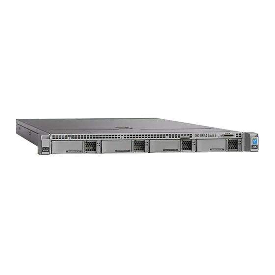
Panel LEDs, on page 7 for a description of the LEDs. Figure 4: FMC 1600 Front Panel Drive bays Power button/power status LED Supports two SAS HDDs in slots 1 and Cisco Firepower Management Center 1600, 2600, and 4600 Hardware Installation Guide... - Page 10 The following figure shows the front panel features and disk-drive configuration for the FMC 4600. See Front Panel LEDs, on page 7 for a description of the LEDs. Cisco Firepower Management Center 1600, 2600, and 4600 Hardware Installation Guide...
-
Page 11: Front Panel Leds
Pullout asset card KVM port Not supported; use the VGA and USB keyboard ports instead. Front Panel LEDs The following figure shows the front panel LEDs and describes their states. Cisco Firepower Management Center 1600, 2600, and 4600 Hardware Installation Guide... - Page 12 • Amber—The chassis is in standby • Blue, flashing—The unit mode. identification function is activated. • Green—The chassis is in main power mode. Power is supplied to all components. Cisco Firepower Management Center 1600, 2600, and 4600 Hardware Installation Guide...
- Page 13 • Green—One or more Ethernet fans breached the unrecoverable ports are link-active, but there is threshold. no activity. • Green, flashing—One or more Ethernet ports are link-active with activity. Cisco Firepower Management Center 1600, 2600, and 4600 Hardware Installation Guide...
-
Page 14: Rear Panel
Rear Panel Note Although the Cisco Integrated Management Controller (CIMC) is not supported on the FMC, you can use Lights-Out-Management (LOM) on the default management interface (eth0) on a Serial Over LAN (SOL) connection to remotely monitor or manage the FMC system. For information about using LOM and SOL, see... -
Page 15: Rear Panel Leds
• Off—No link is present. • Amber—Link speed is 1 Gbps. • Green—Link is active. • Green—Link speed is 10 Gbps. • Green, flashing—Traffic is present on the active link. Cisco Firepower Management Center 1600, 2600, and 4600 Hardware Installation Guide... -
Page 16: Power Supply
Nominal range: 100 to 120 V AC, 200 to 240 V AC Range: 90–132 V AC, 180–264 V AC AC input frequency Nominal range: 50–60 Hz Range: 47–63 Hz Cisco Firepower Management Center 1600, 2600, and 4600 Hardware Installation Guide... -
Page 17: Hardware Specifications
Relative humidity Operating: 8 to 90% noncondensing Nonoperating: 5 to 95% noncondensing Altitude Operating: 0 to 10,000 ft Nonoperating: 0 to 40,000 ft when the appliance is stored or transported Cisco Firepower Management Center 1600, 2600, and 4600 Hardware Installation Guide... -
Page 18: Product Id Numbers
Note Only the approved power cords and jumper cords provided with the FMC 1600, 2600, and 4600 are supported. The following power cords and jumper cords are supported. Cisco Firepower Management Center 1600, 2600, and 4600 Hardware Installation Guide... - Page 19 Plug: A.S. 3112-2000 Cord set rating: 10 A, 250 V Connector: IEC 60320/C15 Figure 12: Brazil PWR-250V-10A-BZ Plug: NBR 14136 Cord set rating: 10 A, 250 V Connector: IEC 60320/C13 Cisco Firepower Management Center 1600, 2600, and 4600 Hardware Installation Guide...
- Page 20 Cord set rating: 10 A, 250 V Connector: HS10S, C-13 to C-14 (recessed receptacle) Figure 15: Cabinet Jumper CAB-C13-CBN Plug: SS10A Cord set rating: 10 A, 250 V Connector: HS10S, C-13 to C-14 Cisco Firepower Management Center 1600, 2600, and 4600 Hardware Installation Guide...
- Page 21 Cord set rating: 10 A/16 A, 250 V Connector: IEC 60320/C15 (VSCC 15) Figure 18: India CAB-250V-10A-ID Plug: IS 6538-1971 Cord set rating: 16 A, 250 V Connector: IEC 60320-C13 Cisco Firepower Management Center 1600, 2600, and 4600 Hardware Installation Guide...
- Page 22 Cord set rating: 10 A, 250 V Connector: IEC 60320/C15 (EN 60320/C15M) Figure 21: Japan CAB-JPN-3PIN Plug: JIS 8303 Cord set rating: 12 A, 125 V Connector: IEC 60320/C13 Cisco Firepower Management Center 1600, 2600, and 4600 Hardware Installation Guide...
- Page 23 Plug: EL211 (KSC 8305) Cord set rating: 10 A, 250 V Connector: IEC 60320/C15 Figure 24: North America CAB-9K12A-NA Plug: NEMA5-15P Cord set rating: 13 A, 125 V Connector: IEC 60320/C15 Cisco Firepower Management Center 1600, 2600, and 4600 Hardware Installation Guide...
- Page 24 Plug: NEMA L6-20 (molded twist lock) Cord set rating: 13 A, 250 V Connector: IEC 60320/C13 Figure 27: Switzerland CAB-9K10A-SW Plug: SEV 1011 (MP232-R) Cord set rating: 10 A, 250 V Connector: IEC 60320/C15 Cisco Firepower Management Center 1600, 2600, and 4600 Hardware Installation Guide...
- Page 25 Plug: EL 302 (CNS10917) Cord set rating: 10 A, 125 V Connector: IEC 60320/C13 Figure 29: United Kingdom CAB-9K10A-UK Plug: BS1363A/SS145 Cord set rating: 10 A, 250 V Connector: IEC 60320/C15 Cisco Firepower Management Center 1600, 2600, and 4600 Hardware Installation Guide...
- Page 26 Overview Power Cord Specifications Cisco Firepower Management Center 1600, 2600, and 4600 Hardware Installation Guide...
-
Page 27: Installation Preparation
This product relies on the building’s installation for short-circuit (overcurrent) protection. Ensure that the protective device is rated not greater than: USA: 120 V, 15 A (EU: 250 V, 16 A) Cisco Firepower Management Center 1600, 2600, and 4600 Hardware Installation Guide... - Page 28 This equipment must be grounded. Never defeat the ground conductor or operate the equipment in the absence of a suitably installed ground conductor. Contact the appropriate electrical inspection authority or an electrician if you are uncertain that suitable grounding is available. Cisco Firepower Management Center 1600, 2600, and 4600 Hardware Installation Guide...
-
Page 29: Safety Recommendations
Then, if an electrical accident occurs, you can act quickly to turn off the power. • Do not work alone if potentially hazardous conditions exist anywhere in your work space. Cisco Firepower Management Center 1600, 2600, and 4600 Hardware Installation Guide... -
Page 30: Prevent Esd Damage
Power Supply Considerations Power Supply, on page 12 for more detailed information about the power supply in the chassis. When installing the chassis, consider the following: Cisco Firepower Management Center 1600, 2600, and 4600 Hardware Installation Guide... -
Page 31: Rack Configuration Considerations
• Baffles can help to isolate exhaust air from intake air, which also helps to draw cooling air through the chassis. The best placement of the baffles depends on the airflow patterns in the rack. Experiment with different arrangements to position the baffles effectively. Cisco Firepower Management Center 1600, 2600, and 4600 Hardware Installation Guide... - Page 32 Installation Preparation Rack Configuration Considerations Cisco Firepower Management Center 1600, 2600, and 4600 Hardware Installation Guide...
-
Page 33: Mount And Connect
• Model and serial number of the damaged unit • Description of damage • Effect of damage on the installation Rack-Mount the Chassis You can install the chassis in a rack using the Cisco rack kit. Cisco Firepower Management Center 1600, 2600, and 4600 Hardware Installation Guide... - Page 34 • The slide rails for the chassis have an adjustment range of 24 to 36 in. (610 to 914 mm). Note The slide rails supplied by Cisco Systems for the chassis do not require tools for installation if you install them in a rack that has square 0.38-in. (9.6 mm), round 0.28-in. (7.1 mm), or #12-24 UNC threaded holes.
- Page 35 Slide the release clip toward the rear on both inner rails, and then continue pushing the chassis into the rack until its front slam latches engage with the rack posts Cisco Firepower Management Center 1600, 2600, and 4600 Hardware Installation Guide...
-
Page 36: Connect Cables, Turn On Power, And Verify Connectivity
Although the CIMC is not supported on the FMC, you can use LOM on the default management interface (eth0) on a SOL connection to remotely monitor or manage the FMC system. For information about using LOM and SOL, see the Cisco Firepower Management Center Getting Started Guide for Models 1600, 2600, and 4600 for your model. - Page 37 Figure 33: Cable Connections eth2 management interface eth3 management interface 10 Gigabit Ethernet SFP+ support 10 Gigabit Ethernet SFP+ support Use only Cisco supported SFP+s Use only Cisco supported SFP+s transceivers. transceivers. Cisco Firepower Management Center 1600, 2600, and 4600 Hardware Installation Guide...
- Page 38 10-Gigabit Ethernet SFP+ interfaces, install any Cisco-supported SFP+ transceivers and cables as needed. You can connect these interfaces to the same or different network from your other management interfaces depending on your network needs. For more information about management...
- Page 39 To avoid data loss or damage to your operating system, perform a graceful shutdown of the operating system. • Graceful shutdown—Press and release the Power button. The operating system performs a graceful shutdown and the FMC goes into standby mode. The power LED is amber. Cisco Firepower Management Center 1600, 2600, and 4600 Hardware Installation Guide...
- Page 40 Only trained and qualified personnel should be allowed to install, replace, or service this equipment. Warning Statement 1073—No User-Serviceable Parts No serviceable parts inside. To avoid risk of electric shock, do not open. Cisco Firepower Management Center 1600, 2600, and 4600 Hardware Installation Guide...
- Page 41 Figure 34: Remove the Drive Ejector handle Release button Step 2 Remove the four drive-tray screws that secure the drive to the tray and then lift the drive out of the tray. Cisco Firepower Management Center 1600, 2600, and 4600 Hardware Installation Guide...
- Page 42 Caution When you replace power supplies, do not mix power supply types in the FMC. Both power supplies must be the same wattage and Cisco PID. Cisco Firepower Management Center 1600, 2600, and 4600 Hardware Installation Guide...
- Page 43 Statement 1074—Comply with Local and National Electrical Codes To reduce risk of electric shock or fire, installation of the equipment must comply with local and national electrical codes. Step 1 Remove the power supply: Cisco Firepower Management Center 1600, 2600, and 4600 Hardware Installation Guide...
- Page 44 Push the power supply into the bay until the release lever locks. c) Connect the power cord to the new power supply. d) If you shut down the FMC, press the Power button to return it to main power mode. Cisco Firepower Management Center 1600, 2600, and 4600 Hardware Installation Guide...