
Summary of Contents for Pentair HIGH POWER WIRELESS LINK KIT
-
Page 1: Installation Guide
HIGH POWER WIRELESS LINK KIT FOR INTELLICENTER™, INTELLITOUCH AND EASYTOUCH ® ® CONTROL SYSTEMS INSTALLATION GUIDE IMPORTANT SAFETY INSTRUCTIONS READ AND FOLLOW ALL INSTRUCTIONS SAVE THESE INSTRUCTIONS... -
Page 2: Table Of Contents
Phone: (800) 831-7133 - www.pentair.com Contents FCC Regulatory Safety Notice ................3 High Power Wireless Link Kit Overview ............. 4 High Power Wireless Link Kit Contents .............. 4 High Power Wireless Link Indoor Transceiver LEDs and Connectors ....5 High Power Wireless Link For ScreenLogic Interface Systems ....6 Mounting Indoor Transceiver ................ -
Page 3: Fcc Regulatory Safety Notice
Note: The user is cautioned that changes and modifications made to the IntelliCenter, EasyTouch and IntelliTouch Control System without the approval of the manufacturer could void the user’s authority to operate this equipment. High Power Wireless Link Kit Installation Guide... -
Page 4: High Power Wireless Link Kit Overview
Indoor transceiver Cable (for connection to (screws) and base ScreenLogic Interface ® Protocol Adapter (purchased separately) AC Power Adapter Outdoor Transceiver enclosure Outdoor Cable (white - 15 ft.) High Power Wireless Link Kit High Power Wireless Link Kit Installation Guide... -
Page 5: High Power Wireless Link Indoor Transceiver Leds And Connectors
IMPORTANT NOTICE: Be sure the (Outdoor transceiver) yellow ID label (8-digit ID number XXXXXXXX) located on the front side of the Indoor transceiver and the ID number on the outdoor transceiver circuit board are the same. High Power Wireless Link Kit Installation Guide... -
Page 6: High Power Wireless Link For Screenlogic Interface Systems
Insert the screws into the wall plug. Don’t insert the screws all the way into the wall, leave about 1/16 in for the wireless transceiver to hang on the head of the screws (see Figure 2 on next page). Mount the wireless transceiver onto both screw heads. High Power Wireless Link Kit Installation Guide... - Page 7 Screw hole (x2) Wall screw hole (2x) Figure 2: Wall Mount the Indoor Wireless Transceiver HPW Link Indoor Transceiver Mounting Screws Location 2½ in Figure 3: Wall Mount Template for HPW Link Indoor Transceiver High Power Wireless Link Kit Installation Guide...
-
Page 8: Mounting Outdoor Transceiver
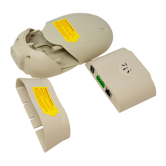
RS-485 COM Port on Automation Control System on the next page. Slide the case over the circuit board and antenna into the back plate. Secure the circuit board in the case using the two retaining screws. High Power Wireless Link Kit Installation Guide... - Page 9 HPW Link Outdoor Transceiver circuit board RS-485 - Connect 4-conductor communication Case cable to terminal screws. Back plate for mounting circuit board Transceiver case retaining screws (x2) Figure 4. HPW Link Outdoor Transceiver High Power Wireless Link Kit Installation Guide...
- Page 10 Inside Low voltage race- HIGH -VOLTAGE FRONT COVER Outdoor Grommet PANEL transceiver| (under side communication of Load cable Center (connect to COM port) Figure 5. IntelliTouch ® or EasyTouch ® Control System Load Center High Power Wireless Link Kit Installation Guide...
- Page 11 After the Power Center is powered up the HPW Link outdoor transceiver will automatically synchronize with the system and will be ready for operation. Note: The initial connection can take up to 2-3 minutes. High Power Wireless Link Kit Installation Guide...
- Page 12 High Power Wireless Link Kit Installation Guide...
-
Page 13: Intellicenter Control System (Replacing Existing Wireless Antenna With Hpw Link)
Power Module DC-IN socket and the plug other end into a AC wall outlet. System Start-Up Refer to the IntelliCenter Control System using the step-by-step Setup Wizard. For more information refer to the IntelliCenter™ Control System User’s Guide (P/N 522990). High Power Wireless Link Kit Installation Guide... - Page 14 Transceiver Power Module Ethernet (Cat5) Cable From (from HPW transceiver Ethernet Place the IntelliCenter™ Control Port (J14) Power Module System main circuit in the low voltage board compartment Figure 7. Power Module Connection High Power Wireless Link Kit Installation Guide...
-
Page 15: Intellicenter Control System (Without An Existing Transceiver)
Connect the other end of the Ethernet cable to the HPW Link indoor transceiver. 12. Power Module Connection: Connect the AC Power Adapter plug into the Power Module DC-IN socket and the plug other end into a AC wall outlet. High Power Wireless Link Kit Installation Guide... - Page 16 1620 HAWKINS AVE., SANFORD, NC 27330 • (919) 566-8000 10951 WEST LOS ANGELES AVE., MOORPARK, CA 93021 • (805) 553-5000 WWW.PENTAIR.COM All Pentair trademarks and logos are owned by Pentair or by one of its global affiliates. ScreenLogic ® EasyTouch...