Table of Contents
Advertisement
3-097-354-11(1)
Home Theatre
System
Operating Instructions
Owner's Record
The model and serial numbers are located on the rear of the unit. Record the
serial number in the space provided below. Refer to them whenever you call
upon your Sony dealer regarding this product.
Model No.
Serial No.
HT-DDW995
©2007 Sony Corporation
Advertisement
Table of Contents

Related Manuals for Sony HT-DDW99


Summary of Contents for Sony HT-DDW99
-
Page 1: Operating Instructions
Owner’s Record The model and serial numbers are located on the rear of the unit. Record the serial number in the space provided below. Refer to them whenever you call upon your Sony dealer regarding this product. Model No. Serial No. -
Page 2: Note To Catv System Installer
WARNING To reduce the risk of fire or electric shock, do not expose this apparatus to rain or moisture. To prevent fire, do not cover the ventilation of the apparatus with newspapers, table-cloths, curtains, etc. And don’t place lighted candles on the apparatus. -
Page 3: About This Manual
About This Manual • The instructions in this manual are for model HT-DDW995. In this manual, models of area code U is used for illustration purposes unless stated otherwise. Any difference in operation is clearly indicated in the text, for example, “Models of area code SP only”. -
Page 4: Table Of Contents
Table of Contents Getting Started Description and location of parts...5 1: Installing speakers ...15 2: Connecting speakers...17 3a: Connecting the audio components...18 3b: Connecting the video components ...19 4: Connecting the antennas...27 5: Preparing the receiver and the remote ...28 6: Selecting the speaker system ...29 7: Calibrating the appropriate settings automatically... -
Page 5: Getting Started
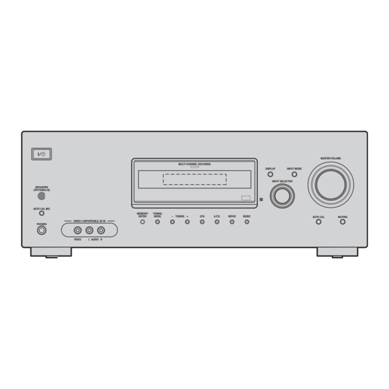
Getting Started Description and location of parts Receiver Front panel SPEAKERS (OFF/A/B/A+B) AUTO CAL MIC VIDEO 3 IN/PORTABLE AV IN PHONES VIDEO L AUDIO R Name Function A ?/1 Press to turn the receiver on (on/standby) or off (page 28, 37, 38, 54, 77). - Page 6 Name Function L 2CH Press to select a sound field (page 49, 51, 53). A.F.D. MOVIE MUSIC M TUNING +/– Press to scan a station (page 55, 58). N TUNING MODE Press to select the tuning mode (page 55, 77). O MEMORY/ Press to store a station or ENTER...
- Page 7 About the indicators on the display SP A SP B Name Function A SW Lights up when the audio signal is output from the SUB WOOFER jack. B LFE Lights up when the disc being played back contains an LFE (Low Frequency Effect) channel and the LFE channel signal is actually being...
- Page 8 Name Function M HDMI Lights up when the receiver recognizes a component connected via a HDMI IN jack (page 20). N Playback The letters (L, C, R, etc.) channel indicate the channels being indicators played back. The boxes around the letters vary to show how the receiver downmixes the source sound.
-
Page 9: Rear Panel
Rear panel DIGITAL DVD IN VIDEO 2/BD IN (ASSIGNABLE) OPTICAL ANTENNA HDMI VIDEO 2/ BD IN COAXIAL VIDEO IN VIDEO IN VIDEO OUT VIDEO IN DMPORT AUDIO IN AUDIO IN AUDIO OUT AUDIO IN SA-CD/CD/CD-R VIDEO 1 A DIGITAL INPUT/OUTPUT section OPTICAL Connects to a DVD IN jack... - Page 10 TV (page 22). Remote commander Connects to Super You can use the supplied remote to operate the Audio CD player, receiver and to control the Sony audio/video CD player, etc. (page 18). components that the remote is assigned to operate.
- Page 11 VCR, CD player, VCD player, LD player, MD deck, DAT deck, tape deck, satellite tuner, Blu-ray disc recorder or PSX. To enter the value of Sony TV, press TV (Z) and then press ENTER. MEMORY Press to store a station during tuner operation.
- Page 12 Press to display and select items TOOLS from the option menus for DVD player or DVD/VHS COMBO. To display the options of Sony TV, press TV (Z) and then press OPTIONS TOOLS. L MENU Press to display the menus of...
- Page 13 DVD player, Blu-ray disc recorder, PSX, DVD/VHS COMBO or satellite tuner is displayed on the TV screen. To return to the previous menu of Sony TV, press TV (Z) and then press RETURN/EXIT O. After pressing RECEIVER (D), press MENU (L) for...
- Page 14 Notes • Some functions explained in this section may not work depending on the model. • The above explanation is intended to serve as an example only. Therefore, depending on the component, the above operation may not be possible or may operate differently than described. •...
-
Page 15: 1: Installing Speakers
1: Installing speakers To fully enjoy theater-like multi channel surround sound requires five speakers (two front speakers, a center speaker, and two surround speakers) and a sub woofer (5.1 channel). Example of a 5.1 channel speaker system configuration AFront speaker (Left) BFront speaker (Right) CCenter speaker DSurround speaker (Left) - Page 16 • Contact a screw shop or installer regarding the wall material or screws to be used. • Sony is not responsible for accident or damage caused by improper installation, insufficient wall strength or improper screw installation, natural calamity, etc.
-
Page 17: 2: Connecting Speakers
2: Connecting speakers DVD IN VIDEO 2/BD IN HDMI VIDEO IN VIDEO IN VIDEO OUT VIDEO IN VIDEO OUT SAT IN DVD IN VIDEO 1 IN MONITOR COMPONENT VIDEO AUDIO OUT FRONT B AUDIO IN AUDIO IN AUDIO OUT AUDIO IN VIDEO 1 WOOFER SPEAKERS FRONT B... -
Page 18: 3A: Connecting The Audio Components
To connect the speakers correctly Check the speaker type by referring to the speaker label* on the rear panel of the speakers. Character on Speaker type speaker label Front left Front right Surround left Surround right * The center speaker and sub woofer do not have any character on the speaker label. -
Page 19: 3B: Connecting The Video Components
3b: Connecting the video components How to hook up your components This section describes how to hook up your components to this receiver. Before you begin, refer to “Component to be connected” below for the pages which describe how to connect each component. -
Page 20: Connecting Components With Hdmi Jacks
COAXIAL DMPORT SA-CD/CD/CD-R A HDMI cable (not supplied) We recommend that you use a Sony HDMI cable. HDMI feature A digital audio signals transmitted by HDMI can be output from the speakers connected to this receiver. This signal supports Dolby Digital, DTS and linear PCM. - Page 21 (page 63). Notes on HDMI connections • Use an HDMI cable with the HDMI logo (made by Sony). • An audio signal input to the HDMI IN jack is output from the SPEAKERS jacks and HDMI OUT jack. It is not output from any other audio jacks.
-
Page 22: Connecting A Tv
Connecting a TV The image from a visual component connected to this receiver and the menu of this receiver can be displayed on a TV screen. It is not necessary to connect all the cords. Connect audio and video cords according to the jacks of your components. -
Page 23: Connecting A Dvd Player
Connecting a DVD player/DVD recorder The following illustration shows how to connect a DVD player/DVD recorder. It is not necessary to connect all the cords. Connect audio and video cords according to the jacks of your components. 1 Connecting a DVD player Audio signals DIGITAL DVD IN... -
Page 24: Connecting A Dvd Recorder
2 Connecting a DVD recorder Audio signals AUDIO AUDIO DIGITAL (ASSIGNABLE) OPTICAL ANTENNA VIDEO 2/ BD IN COAXIAL DMPORT SA-CD/CD/CD-R A Audio cord (not supplied) B Video cord (not supplied) C Component video cord (not supplied) • Be sure to program the VIDEO 1 input button on the remote so that you can use the button to control your DVD recorder. -
Page 25: Connecting A Satellite Tuner
Connecting a satellite tuner/ Set-top box The following illustration shows how to connect a satellite tuner or set-top box. It is not necessary to connect all the cords. Connect audio and video cords according to the jacks of your components. Satellite tuner/Set-top box Audio signals Video signals... - Page 26 Connecting components with analog video and audio jack The following illustration shows how to connect a component which has analog jacks such as a VCR, etc. Audio signals AUDIO AUDIO DIGITAL (ASSIGNABLE) OPTICAL ANTENNA VIDEO 2/ BD IN COAXIAL DMPORT SA-CD/CD/CD-R To the VIDEO 3 IN/PORTABLE AV IN jacks Camcorder/...
-
Page 27: 4: Connecting The Antennas
4: Connecting the antennas Connect the supplied AM loop antenna and FM wire antenna. FM wire antenna (supplied) DIGITAL DVD IN (ASSIGNABLE) OPTICAL ANTENNA VIDEO 2/ BD IN COAXIAL VIDEO IN DMPORT AUDIO IN SA-CD/CD/CD-R * The shape of the connector varies depending on the area code of this receiver. -
Page 28: 5: Preparing The Receiver And The Remote
5: Preparing the receiver and the remote Connecting the AC power cord Connect the AC power cord to a wall outlet. AC power cord CENTER To the wall outlet Performing initial setup operations Before using the receiver for the first time, initialize the receiver by performing the following procedure. -
Page 29: 6: Selecting The Speaker System
Inserting batteries into the remote Insert two R6 (size-AA) batteries in the RM-AAP017 remote commander. Observe the correct polarity when installing batteries. Notes • Do not leave the remote in an extremely hot or humid place. • Do not use a new battery with old ones. •... -
Page 30: 7: Calibrating The Appropriate Settings Automatically (Auto Calibration)
7: Calibrating the appropriate settings automatically (AUTO CALIBRATION) This receiver is equipped with D.C.A.C. (Digital Cinema Auto Calibration) Technology which allows you to perform automatic calibration as follows: • Check the connection between each speaker and the receiver. • Adjust the speaker level. •... - Page 31 Performing Auto Calibration AV ?/1 RM SET UP SYSTEM STANDBY VIDEO 1 VIDEO 2 VIDEO 3 SA-CD/CD TUNER Input buttons DMPORT RECEIVER A.F.D. MOVIE MUSIC SLEEP FM MODE D. TUNING AUTO CAL – /– – 0/10 CLEAR ENTER >10 MEMORY GUIDE DISPLAY OPTIONS...
- Page 32 Error and warning codes Error codes When an error is detected during Auto Calibration, an error code will appear on the display cyclically after each measurement process as follows: Error code t blank display t (error code t blank display) t PUSH t blank display t ENTER Appears when there are more than one error code.
-
Page 33: 8: Adjusting The Speaker Levels And Balance (Test Tone)
Warning codes and solutions Warning Explanation Solution code WARN. 40 The environment Make sure the is noisy. environment is quiet during Auto Calibration. WARN. 50 The center speaker Be sure to connect is not connected. the center speaker. WARN. 51 The surround Be sure to connect speakers are not the surround... - Page 34 Press RECEIVER. The RECEIVER indicator lights up and receiver operation is activated. Press MENU. “1-LEVEL” appears on the display. Press the or b to enter the menu. Press V/v repeatedly to select “T. TONE”. or b to enter the Press the parameter.
-
Page 35: Playback
Playback Selecting a component SYSTEM STANDBY VIDEO 1 VIDEO 2 VIDEO 3 SA-CD/CD DMPORT A.F.D. MOVIE SLEEP FM MODE D. TUNING – /– – 0/10 CLEAR >10 MEMORY GUIDE RETURN/ MENU EXIT REPLAY ADVANCE < < TUNING – DISC SKIP TV VOL TV CH MASTER VOL... - Page 36 To avoid damaging your speakers Before you turn off the receiver, be sure to turn down the volume level. To listen to the sub woofer Be sure to use the buttons on the sub woofer for this operation. Press POWER. The POWER indicator lights up.
-
Page 37: Listening/Watching A Component
TV CH MASTER VOL PRESET MUTING Notes • The operation is described for a Sony Super Audio CD player. • Refer to the operating instructions supplied with the Super Audio CD player or CD player. Tips • You can select the sound field to suit the music. -
Page 38: Watching A Dvd
Watching a DVD RM SET UP AV ?/1 SYSTEM STANDBY VIDEO 1 VIDEO 2 VIDEO 3 SA-CD/CD TUNER DMPORT RECEIVER A.F.D. MOVIE MUSIC SLEEP FM MODE D. TUNING AUTO CAL – /– – 0/10 CLEAR ENTER >10 MEMORY GUIDE DISPLAY OPTIONS RETURN/ MENU... -
Page 39: Amplifier Operations
Amplifier Operations Navigating through menus By using the amplifier menus, you can make various adjustments to customize the receiver. SA-CD/CD TUNER DMPORT RECEIVER A.F.D. MOVIE MUSIC SLEEP FM MODE D. TUNING AUTO CAL – /– – 0/10 CLEAR ENTER >10 MEMORY GUIDE DISPLAY... -
Page 40: Overview Of The Menus
Overview of the menus The following options are available in each menu. For details on navigating through menus, see page 39. Menu Parameters [Display] [Display] LEVEL (42) Test tone [1-LEVEL] Front speaker balance [FRT BAL] Center speaker level [CNT LVL] Surround left speaker level [SL LVL] Surround right speaker level... - Page 41 Menu Parameters [Display] [Display] AUDIO (44) Digital audio input decoding [5-AUDIO] priority [DEC. PRI.] Digital broadcast language selection [DUAL] Synchronizes audio with video output [A.V. SYNC.] Digital audio input assignment [D.ASSIGN] Naming inputs VIDEO (45) DIGITAL MEDIA PORT video [6-VIDEO] assign [DMPORT V.] HDMI AUDIO...
-
Page 42: Adjusting The Level (Level Menu)
Adjusting the level (LEVEL menu) You can use the LEVEL menu to adjust the balance and level of each speaker. These settings are applied to all sound fields. Select “1-LEVEL” in the amplifier menus. For details on adjusting the parameters, see “Navigating through menus”... -
Page 43: Adjusting The Tone (Tone Menu)
Adjusting the tone (TONE menu) You can use the TONE menu to adjust the tonal quality (bass/treble level) of the front speakers. Select “2-TONE” in the amplifier menus. For details on adjusting the parameters, see “Navigating through menus” (page 39) and “Overview of the menus”... -
Page 44: Settings For The Tuner (Tuner Menu)
Settings for the tuner (TUNER menu) You can use the TUNER menu to set the FM station receiving mode and to name preset stations. Select “4-TUNER” in the amplifier menus. For details on adjusting the parameters, see “Navigating through menus” (page 39) and “Overview of the menus”... -
Page 45: Settings For The Video (Video Menu)
x DUAL (Digital broadcast language selection) Lets you select the language you want to listen to during digital broadcast. This feature only functions for Dolby Digital sources. • DUAL M/S (Main/Sub) Sound of the main language will be output through the front left speaker and sound of the sub language will be output through the front right speaker simultaneously. -
Page 46: Settings For The System (System Menu)
• TV+AMP The sound is output from TV’s speaker and the speakers connected to the receiver. Notes • The sound quality of the playback component depends on the TV’s sound quality, such as the number of channels, and the sampling frequency, etc. -
Page 47: Speaker Distance
x SL DIST. (Surround left speaker distance) Lets you set the distance from your listening position to the surround left speaker. Surround left speaker distance should be set from a distance equal to the front speaker distance (A on page 46) to a distance15 feet closer to your listening position (C on page 46). -
Page 48: Calibrating The Appropriate Settings Automatically (A. Cal Menu)
Surround speaker position is designed specifically for implementation of the Cinema Studio EX modes. For other sound fields, speaker position is not so critical. Those sound fields were designed under the premise that the surround speakers would be located behind the listening position, but presentation remains fairly consistent even with the surround speakers positioned at a rather wide angle. -
Page 49: Enjoying Surround Sound
Enjoying Surround Sound Enjoying Dolby Digital and DTS Surround sound (AUTO FORMAT DIRECT) The Auto Format Direct (A.F.D.) mode allows you to listen to higher fidelity sound and select the decoding mode for listening to a 2 channel stereo sound as multi channel sound. DMPORT RECEIVER A.F.D. - Page 50 Types of A.F.D. mode Decoding A.F.D. mode mode [Display] (Detecting A.F.D. AUTO automatically) [A.F.D. AUTO] Dolby Pro Logic PRO LOGIC [DOLBY PL] Dolby Pro Logic PRO LOGIC II MOVIE [PLII MV] PRO LOGIC II MUSIC [PLII MS] (Multi Stereo) MULTI STEREO [MULTI ST.] Multi channel Effect...
-
Page 51: Selecting A Pre-Programmed Sound Field
Selecting a pre- programmed sound field You can take advantage of surround sound simply by selecting one of the receiver’s pre- programmed sound fields. They bring the exciting and powerful sound of movie theaters and concert halls into your home. DMPORT RECEIVER A.F.D. - Page 52 Effect Reproduces the sound characteristics of the Sony Pictures Entertainment “Cary Grant Theater” cinema production studio. This is a standard mode, great for watching almost any type of movie.
-
Page 53: Using Only The Front Speakers And Sub Woofer (2Ch Stereo)
CINEMA STUDIO EX modes are suitable for watching motion picture DVDs (etc.), with multi channel surround effects. You can reproduce the sound characteristics of Sony Pictures Entertainment’s dubbing studio in your home. The CINEMA STUDIO EX modes consist of the following three elements. -
Page 54: Resetting Sound Fields To The Initial Settings
Resetting sound fields to the initial settings Be sure to use the buttons on the receiver for this operation. MULTI CHANNEL DECODING SPEAKERS (OFF/A/B/A+B) AUTO CAL MIC MEMORY/ TUNING ENTER MODE TUNING A.F.D. MOVIE VIDEO 3 IN/PORTABLE AV IN PHONES VIDEO L AUDIO R Press ?/1 to turn off the power. -
Page 55: Automatic Tuning
Automatic tuning SYSTEM STANDBY VIDEO 1 VIDEO 2 VIDEO 3 SA-CD/CD DMPORT RECEIVER A.F.D. MOVIE SLEEP FM MODE D. TUNING MODE – /– – 0/10 CLEAR ENTER >10 MEMORY GUIDE RETURN/ MENU EXIT REPLAY ADVANCE < < TUNING – DISC SKIP Press TUNER repeatedly to select the FM or AM band. -
Page 56: Presetting Radio Stations
Direct tuning Enter the frequency of a station directly by using the numeric buttons. SYSTEM STANDBY VIDEO 1 VIDEO 2 VIDEO 3 SA-CD/CD DMPORT A.F.D. MOVIE SLEEP FM MODE D. TUNING – /– – 0/10 CLEAR ENTER >10 MEMORY Press TUNER repeatedly to select the FM or AM band. -
Page 57: Tuning To Preset Stations
Tune in the station that you want to preset using Automatic Tuning (page 55) or Direct Tuning (page 56). Switch the FM reception mode, if necessary (page 55). Press MEMORY. You can also use MEMORY/ENTER on the receiver. “MEMORY” lights up for a few seconds. Perform steps 4 and 5 before “MEMORY”... -
Page 58: Naming Preset Stations
Press PRESET + or PRESET – repeatedly to select the preset station you want. Each time you press the button, you can select a preset station as follows: You can also press the numeric buttons to select the preset station you want. Then, press ENTER to enter the selection. -
Page 59: Other Operations
Other Operations Switching the audio input mode (INPUT MODE) You can select the audio input mode by setting the audio input mode when you connect components to both digital and analog audio input jacks on the receiver. Turn INPUT SELECTOR on the receiver to select the input. -
Page 60: Connecting The Digital Media Port Adapter
Connecting the DIGITAL MEDIA PORT adapter You can listen to the sound from the component connected through the DIGITAL MEDIA PORT adapter to the DMPORT jack on the receiver. DIGITAL MEDIA PORT adapter * The type of connector varies depending on the DIGITAL MEDIA PORT adapter. For details, see the operating instructions supplied with the DIGITAL MEDIA PORT adapter. - Page 61 Listening to a connected component through DMPORT connection Press DMPORT. You can also use the INPUT SELECTOR on the receiver to select “DMPORT”. Start playback of the connected component. The sound is played back on the receiver. For details, see the operating instructions supplied with the DIGITAL MEDIA PORT adapter.
-
Page 62: Listening To Digital Sound From Other Inputs (Digital Assign)
Listening to digital sound from other inputs (DIGITAL ASSIGN) You can reassign digital audio input that has OPTICAL or COAXIAL (SAT IN, VIDEO 2/BD IN, DVD IN) signals to another input when they are not currently being used. For example, to output the sound source for the DVD player using the OPTICAL IN jack on the receiver: •... -
Page 63: Naming Inputs
Notes • You cannot reassign more than one digital audio inputs to the same input. • You cannot use the digital audio input for the original input when it has been assigned to another input. • When you reassign the digital audio input, the INPUT MODE setting may change automatically (page 59). -
Page 64: Changing The Display
Changing the display You can check the sound field, etc., by changing the information on the display. Be sure to use the buttons on the receiver for this operation. Press DISPLAY repeatedly. Each time you press the button, the display changes cyclically as follows. -
Page 65: Recording Using The Receiver
Recording using the receiver Recording onto a CD-R You can record onto a CD-R using the receiver. See the operating instructions supplied with your CD recorder. Press one of the input buttons to select the playback component. You can also use INPUT SELECTOR on the receiver. -
Page 66: Using The Remote
Furthermore, you can also program the remote for Sony components that the remote is unable to control. Note that the remote can only control components that accept infrared wireless control signals. - Page 67 Use the numeric codes in the tables below to control non-Sony components and also Sony components that the remote is normally unable to control. Since the remote signal that a component accepts differs depending on the...
- Page 68 TELEFUNKEN 751, 752 TOSHIBA 747, 756 ZENITH * If an AIWA VCR does not work even though you enter the code for AIWA, enter the code for Sony instead. To control a DVD player Maker Code(s) SONY 401, 402, 403...
- Page 69 To control a TV Maker Code(s) SONY 501, 502 AIWA 501, 536, 539 AKAI CENTURION CORONADO CURTIS-MATHES 503, 551, 566, 567 DAYTRON 517, 566 DAEWOO 504, 505, 506, 507, 515, 544 FISHER 508, 545 FUNAI FUJITSU GOLDSTAR/LG 503, 512, 515, 517,...
- Page 70 To control a satellite tuner Maker Code(s) SONY 801, 802, 803, 804, 824, 825, 865 AMSTRAD 845, 846 BskyB GENERAL ELECTRIC (GE) GRUNDIG 859, 860 HUMAX 846, 847 THOMSON 857, 861, 864 PACE 848, 849, 850, 852, 862, 863, 864...
-
Page 71: Additional Information
Additional Information Glossary x Component video A format for transmitting video signal information consisting of three separate signals: luminance Y, chrominance Pb, and chrominance Pr. High quality pictures, such as DVD video or HDTV pictures, are transmitted more faithfully. The three jacks are color coded green, blue and red. -
Page 72: Precautions
Precautions On safety Should any solid object or liquid fall into the cabinet, unplug the receiver and have it checked by qualified personnel before operating it any further. On power sources • Before operating the receiver, check that the operating voltage is identical with your local power supply. -
Page 73: Troubleshooting
If you have any questions or problems concerning your receiver, please consult your nearest Sony dealer. Troubleshooting If you experience any of the following difficulties while using the receiver, use this troubleshooting guide to help you remedy the problem. - Page 74 There is no sound from one of the front speakers. • Connect a pair of headphones to the PHONES jack to verify that sound is output from the headphones. If only one channel is output from the headphones, the component may not be connected to the receiver correctly.
- Page 75 The MULTI CHANNNEL DECODING lamp does not light up. • Check that the playback component is connected to a digital jack and the input is selected properly on this receiver. • Check whether the input source of the software being played back corresponds to the multi channel format.
-
Page 76: Error Messages
If the problem persist Consult your nearest Sony dealer. Note that if service personnel changes some parts during repair, these parts may be retained. Reference sections for clearing the receiver’s memory... -
Page 77: Specifications
Specifications AUDIO POWER SPECIFICATIONS POWER OUTPUT AND TOTAL HARMONIC DISTORTION: With 6 ohm loads, both channels driven, from 120 – 20,000 Hz; rated 90 watts per channel minimum RMS power, with no more than 1% total harmonic distortion from 250 milliwatts to rated output. - Page 78 Dimensions (width/height/depth) (Approx.) 430 × 157.5 × 310 mm (17 × 6 1/4 × 12 1/4 inches) including projecting parts and controls Mass (Approx.) 7.8 kg (17 lb 4 oz) Speaker section • Front speakers (SS-MSP900) • Center speaker (SS-CNP680) •...
-
Page 79: Index
Index Numerics 2 channel 53 2CH STEREO 53 5.1 channel 15 AUTO CALIBRATION 30 AUTO FORMAT DIRECT (A.F.D.) 49 Blu-ray disc player connecting 20 CD player connecting 18 playback 37 DIGITAL ASSIGN 62 Digital Cinema Sound (DCS) 52 DIGITAL MEDIA PORT connecting 60 input 35 video assign 61... - Page 80 Sony Corporation Printed in Malaysia...