
Related Manuals for Cameron TYPE 31


Summary of Contents for Cameron TYPE 31
- Page 1 E N G I N E E R E D V A L V E S Installation, Operation and Maintenance Manual ® CAMERON TYPE 31 FULLY WELDED BODY BALL VALVE ® CAMERON Installation, Operation and Maintenance Manual IOM-CAM-BALL-T31...
-
Page 2: Table Of Contents
Installation ............3 Maintenance ............ 6 Trouble Shooting ..........8 Injection Procedures ........10 Valve Cleaning ..........11 Sealant Injection ..........12 Stem Designs ..........15 © Cameron’s Valves & Measurement Group IOM-CAM-BALL-T31 Rev. 0 06/09 Installation, Operation and Maintenance Manual IOM-CAM-BALL-T31... -
Page 3: Bill Of Materials
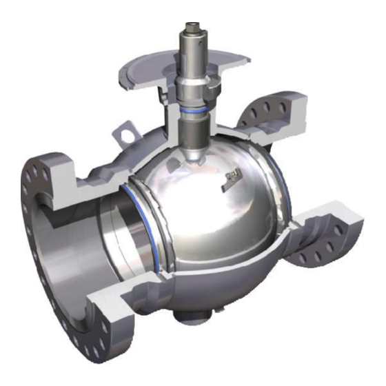
E N G I N E E R E D V A L V E S Bill of Materials Figure 1 - Cameron Fully Welded Body Ball Valve Components. ITEM DESCRIPTION Keyed Shaft Upper Stem Seal* Upper Body Lower Stem Seal... -
Page 4: Scope
One of the most trusted valves in the petroleum Engineered for heavy-duty service and minimal industry, the CAMERON T31 Fully Welded Body Ball maintenance, the CAMERON T31 Fully Welded Valve combines the strength of forged components Body Ball Valve is commonly selected for a with a lightweight and compact spherical design. -
Page 5: Installation
3" (75 mm) from the weld. period of time. Use tempil sticks to check temperatures. Before CAMERON T31 Fully Welded Body Ball Valves are welded into final position in the pipeline, cover the valve seal areas (ball-to-seat area and seat-to-end connection area) with 1"... - Page 6 E N G I N E E R E D V A L V E S Hydrostatic Testing When CAMERON T31 Fully Welded Body Ball Valves 2. Depending on the valve stem and the actuator/ are installed in a piping system that requires hydrostatic...
- Page 7 E N G I N E E R E D V A L V E S Rotary Vane Style Operator (4 Bar Type) 1. Make sure that operating the valve to the fully open and fully closed position will not disrupt current operation of line.
-
Page 8: Maintenance
Longest Operating Time When the valve is being operated, the seat face is exposed. Therefore, to minimize the amount of time in which the seat face is exposed, Cameron Valves & Measurement group recommends a maximum operating time as follows: *Longest Operating Time = 5 x Valve nominal bore (i.e., one minute... - Page 9 Failure to do so could injure you or others. 1. The CAMERON bleed fittings have one or two exhaust ports. You should be aware of their orientation. Any debris in the valve or fitting will be exhausted at a high velocity.
-
Page 10: Troubleshooting
Injection Procedure section on pages 10 - 12. Tighten the stem screw or nut tightly enough to stop the leak. Do not exceed torque value for stem screw. Contact your Cameron The stem Stem screw or nut is loose. Valves & Measurement group representative is leaking. -
Page 11: Troubleshooting
Operate the valve. Stem capscrew or nut is too Tighten the stem screw or nut to the appropriate tight. torque value. Contact your Cameron Valves & Measurement group representative to obtain torque values. Inject a small amount of cleaner into fitting to Trash in fitting. -
Page 12: Injection Procedures
E N G I N E E R E D V A L V E S Injection Procedures Routine Cleaning Steps Procedure Inspect: Seat injection fittings. 1. Inspect valve. Stem injection fitting. (Do not inject into this fitting.) Body / bleed fitting Make sure the grease gun / pump is in working order and loaded with the 2. -
Page 13: Valve Cleaning
E N G I N E E R E D V A L V E S Valve Cleaning Steps Procedure Inspect: Seat injection fittings. 1. Inspect valve. Stem injection fitting. (Do not inject into this fitting.) Body / bleed fitting Make sure the grease gun / pump is in working order and loaded with the 2. -
Page 14: Sealant Injection
- ASME Class -Manufacture Date Measurement group - Serial Number (Refer to nameplate on page 2) Representative. The Cameron Valves & Measurement group representative may be able to provide additional information or schedule an on-site consultation. Installation, Operation and Maintenance Manual IOM-CAM-BALL-T31... - Page 15 E N G I N E E R E D V A L V E S Injection Capacity Chart Valve Volume Volume Volume Volume Size per Seat (oz) per Valve (oz) per Seat (cm ) per Valve (cm ) 2" 3"...
- Page 16 Approved Flush / Sealant The following products are recommended by the cleaner / sealant manufacturers for the indicated service and condition. Contact your Cameron Valves & Measurement group representative for availability through Cameron Valves & Measurement. Cleaner / Sealant Manufacturer...
-
Page 17: Stem Designs
E N G I N E E R E D V A L V E S Stem Designs 1", 1.5" and 2" Stem Design ITEM DESCRIPTION Capscrew Disc Spring Stop Nut Stem Seal Washer Stem Seal Figure 14 - 1", 1 1/2" and 2" Stem Design. 3"... - Page 18 E N G I N E E R E D V A L V E S Stem Designs 4" and Larger Stem Design ITEM DESCRIPTION Disc Spring Keyed Shaft Stud Stem Seal Gland Stem seal Figure 16 - 4"and Larger Stem Design. NOTES Installation, Operation and Maintenance Manual IOM-CAM-BALL-T31...
- Page 19 E N G I N E E R E D V A L V E S NOTES Installation, Operation and Maintenance Manual IOM-CAM-BALL-T31...
- Page 20 E N G I N E E R E D V A L V E S Contact your Cameron’s Valves & Measurement group representative for a Repair Manual ® CAMERON 3250 Briarpark Drive, Suite 300 Houston, Texas 77042 USA Toll Free 800 323 9160 For the most current contact and location information go to: www.c-a-m.com/valvesandmeasurement...