Advertisement
Quick Links
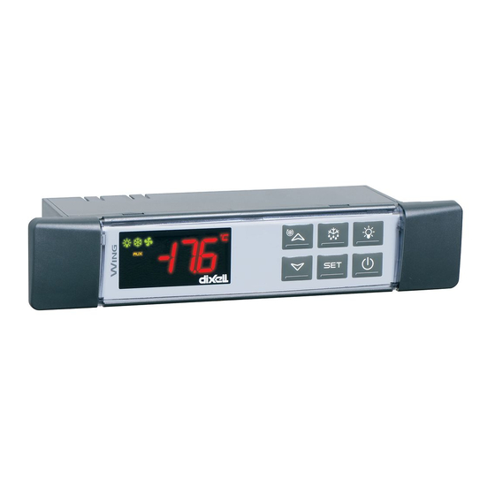
Digital controller with off cycle defrost
XW20LS
1. GENERAL WARNING
1.1 PLEASE READ BEFORE USING THIS MANUAL
•
This manual is part of the product and should be kept near the instrument for easy and quick
reference.
The instrument shall not be used for purposes different from those described hereunder. It cannot be
•
used as a safety device.
Check the application limits before proceeding.
•
Dixell Srl reserves the right to change the composition of its products, even without notice, ensuring
•
the same and unchanged functionality.
1.2
SAFETY PRECAUTIONS
Check the supply voltage is correct before connecting the instrument.
•
Do not expose to water or moisture: use the controller only within the operating limits avoiding sudden
•
temperature changes with high atmospheric humidity to prevent formation of condensation
Warning: disconnect all electrical connections before any kind of maintenance.
•
Fit the probe where it is not accessible by the End User. The instrument must not be opened.
•
•
In case of failure or faulty operation send the instrument back to the distributor or to "Dixell S.r.l." (see
address) with a detailed description of the fault.
Consider the maximum current which can be applied to each relay (see Technical Data).
•
Ensure that the wires for probes, loads and the power supply are separated and far enough from each
•
other, without crossing or intertwining.
•
In case of applications in industrial environments, the use of mains filters (our mod. FT1) in parallel
with inductive loads could be useful.
2. GENERAL DESCRIPTION
Model XW20LS, format 38x185mm, is a digital thermostat with off cycle defrost designed for
refrigeration applications at normal temperature. It has 2 relay outputs to control compressor and light..
It could be provided with a Real Time Clock which allows programming of up to 6 daily defrost cycles,
divided into holidays and workdays. A "Day and Night" function with two different set points is fitted for
energy saving. It is also provided with up to 2 NTC or PTC probe inputs, the first one for temperature
control, the second one, to be located onto the evaporator and to control the defrost termination
temperature. The digital input can operate as third temperature probe, to signal the condenser
temperature alarm or to display a temperature.
The HOT KEY output allows to connect the unit, by means of the external module XJ485-CX, to a
network line ModBUS-RTU compatible such as the dIXEL monitoring units of X-WEB family. It
allows to program the controller by means the HOT KEY programming keyboard.
The instrument is fully configurable through special parameters that can be easily programmed
through the keyboard.
3. CONTROLLING LOADS
3.1 COMPRESSOR
The regulation is performed according to
the temperature measured by the
thermostat probe with a positive
differential from the set point: if the
temperature increases and reaches set
point plus differential the compressor is
started and then turned off when the
temperature reaches the set point value
again.
In case of fault in the thermostat probe the start and stop of the compressor are timed through
parameters "COn" and "COF".
3.2 DEFROST
Defrost is performed through a simple stop of the compressor. The defrost interval depends on the
presence of the RTC (optional). If the RTC is present is controlled by means of parameter "EdF":
with EdF=in the defrost is made every "IdF" time – standard way for controller without RTC.
-
with EdF = "rtc", the defrost is made in real time depending on the hours set in the parameters
-
Ld1..Ld6 on workdays and in Sd1...Sd6 in holidays;
Other parameters are used to control defrost cycles: its maximum length (MdF) and two defrost
modes: timed or controlled by the evaporator's probe (P2P).
4. FRONT PANEL COMMANDS
4.1 STANDARD FRONTAL PANEL
4.2 STEEL FINISHING
1592027320 XW20LS RTC GB r1.0 18.03.2015
: To display target set point; in programming mode it selects a parameter or confirm an
operation.
(DEF) To start a manual defrost
(UP): To see the max. stored temperature; in programming mode it browses the parameter
codes or increases the displayed value.
(DOWN) To see the min stored temperature; in programming mode it browses the parameter
codes or decreases the displayed value.
To switch the instrument off.
To switch the light.
KEY COMBINATIONS:
+
To lock & unlock the keyboard.
+
To enter in programming mode.
+
To return to the room temperature display.
4.3 USE OF LEDS
Each LED function is described in the following table.
LED
MODE
ON
Compressor enabled
Flashing Anti-short cycle delay enabled
ON
Defrost enabled
Flashing Drip time in progress
ON
An alarm is occurring
ON
Continuous cycle is running
ON
Energy saving enabled
ON
Light on
°C/°F ON
Measurement unit
°C/°F Flashing Programming phase
5. MAX & MIN TEMPERATURE MEMORIZATION
5.1 HOW TO SEE THE MIN TEMPERATURE
1.
Press and release the n key.
2.
The "Lo" message will be displayed followed by the minimum temperature recorded.
3.
By pressing the n key again or by waiting 5s the normal display will be restored.
5.2 HOW TO SEE THE MAX TEMPERATURE
1.
Press and release the o key.
2.
The "Hi" message will be displayed followed by the maximum temperature recorded.
3.
By pressing the o key again or by waiting 5s the normal display will be restored.
5.3 HOW TO RESET THE MAX AND MIN TEMPERATURE RECORDED
1.
Hold press the SET key for more than 3s, while the max. or min temperature is displayed. (rSt
message will be displayed)
2.
To confirm the operation the "rSt" message starts blinking and the normal temperature will be
displayed.
6. MAIN FUNCTIONS
6.1 TO SET THE CURRENT TIME AND DAY (ONLY FOR INSTRUMENTS
WITH RTC)
When the instrument is switched on, it's necessary to program the time and day.
1.
Enter the Pr1 programming menu, by pushing the SET + n keys for 3s.
2.
The rtc parameter is displayed. Push the SET key to enter the real time clock menu.
3.
The Hur (hour) parameter is displayed.
4.
Push the SET and set current hour by the UP and Down keys, then push SET to confirm
the value..
5.
Repeat the same operations on the Min (minutes) and dAy (day) parameters.
To exit: Push SET+UP keys or wait for 15 sec without pushing any keys.
6.2 HOW TO SEE THE SET POINT
1.
2.
display the probe value again.
6.3 HOW TO CHANGE THE SET POINT
1.
Push the SET key for more than 2 seconds to change the Set point value;
The value of the set point will be displayed and the "°C" or "°F" LED starts blinking;
2.
3.
To change the Set value push the o or n arrows within 10s.
4.
To memorise the new set point value push the SET key again or wait 10s.
6.4 HOW TO START A MANUAL DEFROST
Push the DEF key for more than 2 seconds and a manual defrost will start.
6.5 HOW TO CHANGE A PARAMETER VALUE
To change the parameter's value operate as follows:
XW20LS
FUNCTION
Push and immediately release the SET key: the display will show the Set
point value;
Push and immediately release the SET key or wait for 5 seconds to
1/5
Advertisement

Related Manuals for Emerson Dixell XW20LS


Summary of Contents for Emerson Dixell XW20LS
- Page 1 : To display target set point; in programming mode it selects a parameter or confirm an operation. Digital controller with off cycle defrost (DEF) To start a manual defrost XW20LS (UP): To see the max. stored temperature; in programming mode it browses the parameter codes or increases the displayed value.
- Page 2 1. Enter the Programming mode by pressing the Set + n keys for 3s (the “°C” or “°F” LED starts DISPLAY blinking). CF Temperature measurement unit: °C=Celsius; °F=Fahrenheit. WARNING: When the 2. Select the required parameter. Press the “SET” key to display its value measurement unit is changed the SET point and the values of the parameters Hy, LS, US, Ot, 3.
-
Page 3: Installation And Mounting
9. TTL SERIAL LINE – FOR MONITORING SYSTEMS Current minute (0 ÷ 59min) Current day (Sun ÷ SAt) The TTL serial line, available through the HOT KEY connector, allows by means of the external First weekly holiday (Sun ÷ nu) Set the first day of the week which follows the holiday times. TTL/RS485 converter, XJ485-CX, to connect the instrument to a monitoring system ModBUS-RTU Second weekly holiday (Sun ÷... -
Page 4: 14. Alarm Signals
Automatically the parameter list of the “Hot Key” is downloaded into the Controller memory, 16.2 XW20LS – DIRECT CONNECTIONS OF LOAD the “doL” message is blinking followed a by flashing “End”. After 10 seconds the instrument will restart working with the new parameters. Remove the “Hot Key”.. - Page 5 Label Name Range °C/°F Level Ld6* 6 workdays defrost start 0 ÷ 23h 50 min. - nu Sd1* 1 holiday defrost start 0 ÷ 23h 50 min. - nu Sd2* 2 holiday defrost start 0 ÷ 23h 50 min. - nu 13.0 Sd3* 3 holiday defrost start...