Siemens SIMATIC S5 Manual
Ip 244 temperature controller with function block fb 162
Hide thumbs
Also See for SIMATIC S5:
- Manual (396 pages) ,
- Equipment manual (197 pages) ,
- Operating instructions manual (43 pages)
Table of Contents
Advertisement
Quick Links
SIMATIC S5 and S7
IP 244
Temperature Controller
with Function Block FB 162
Manual
C79000-G8576-C858-02
Notes for the Reader
IP 244 (-3AA22) Temperature
Controller Instructions
IP 244 B (-3AB31) Temperature
Controller Instructions
IP 244
Programming Instructions
FB 162 (64 Messages)
Programming Instructions
Test Program with FB 162
Utilization in S5
IP 244
Utilization in S7-400
IP 244
Checklist for Start-Up
Glossary
Index
Pocket Guide
1
2
3
4
5
6
7
8
9
10
11
Advertisement
Chapters
Table of Contents

Related Manuals for Siemens SIMATIC S5


Summary of Contents for Siemens SIMATIC S5
- Page 1 Notes for the Reader IP 244 (-3AA22) Temperature Controller Instructions IP 244 B (-3AB31) Temperature SIMATIC S5 and S7 Controller Instructions IP 244 Programming Instructions IP 244 FB 162 (64 Messages) Temperature Controller Programming Instructions with Function Block FB 162...
- Page 2 This device may only be used for the applications described in the catalog or technical description, and only in connection with devices or components from other manufacturers which have been approved or recommended by Siemens. This product can only function correctly and safely if it is transported, stored and set up carefully and correctly, and operated and maintained as recommended.
-
Page 3: Temperature Controller With Function Block Fb
Notes for the Reader This manual describes the SIMATIC S5 temperature controller module IP 244 the software package FB 162 and the test program for the temperature controller module The software is on the accompanying diskette and comprises the following parts: –... - Page 4 Notes for the Reader The following procedure is recommended for problem-free installation and start-up: Load the contents of the supplied diskette into the CPU of the programmable controller using the programmer. Then enter a parameter set. The function block can then be used to transfer the parameters to the tempera ture controller module.
-
Page 5: Table Of Contents
Contents Contents Page Technical Description 2–3 Application 2–3 Design 2–3 Mode of Operation 2–5 Technical Data 2–7 Installation and Operation 2–11 Inserting and Removing the Module 2–11 Connecting Signal Lines and the Power Supply 2–11 2.2.1 Analog Inputs (Plug Connector X3) 2–11 2.2.2 Digital Outputs and One Digital Input (Socket Connector X4) -
Page 6: Technical Description
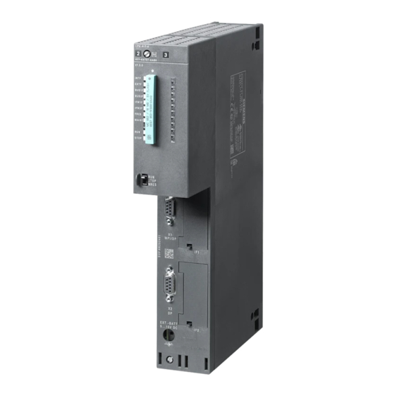
Technical Description 1.1 Application The IP 244 temperature controller can be used in SIMATIC S5-115U, S5-135U and S5-155U programmable controllers and expansion units as an intelligent I/O module for automatic control of machines. When used in the S5-115U, an adapter casing is required (order number: 6ES5 491-0LA11). - Page 7 Technical Description Fig 1.2/1 Front panel IP244 2–4 C79000–B8576–C859–02...
-
Page 8: Mode Of Operation
Technical Description 1.3 Mode of Operation As shown in the block diagram (Fig. 1.3/1), the analog input signals are switched to an analog to digital converter (ADC) by a multiplexer. With a maximum conversion time of 80 ms, the ADC digitalizes the input voltage using the dual slope technique. - Page 9 Technical Description The various functions of the controller module are processed by the microprocessor: – measured value acquisition via multiplexer and ADC – measured value processing according to the control algorithm, (system error formation, manipulated variable calculation, self-optimization) – monitoring limit values of measured values and generation of interrupts –...
-
Page 10: Technical Data
Technical Description 1.4 Technical Data Analog inputs Number of input channels and input voltages: as delivered 0 to 51.2 mV = 2048 13 (channels 0 to 12) – units for thermocouples 0 to 20.48 V = 2048 E 2 (channels 13 and 14) –... - Page 11 Technical Description Additional error caused by voltage divider (e.g. channels 13 and 14) 0.25 % Temperature influence / 10 Kelvin (range 0 to 50 mV) (2 units / 10 Kelvin) Additional error caused by temperature influence / 10 Kelvin in channels with voltage dividers (1 unit / 10 Kelvin) (temperature coefficient of the voltage divider) Error message when tolerance exceeded,...
- Page 12 Technical Description Digital input (heating switch) Input voltage for signal 0 (control off) –2 to + 4.5 V – for signal 1 (control on) +13 to + 35 V – Input current (rated value for 24 V) 5 mA Time delay max.
- Page 13 Technical Description Controller action Control algorithm PID with structuring switches (P, PI, PID) as two or three step controllers; zone controllers with configurable self-adjustment function Cascaded control possible, controller 0 is then master controller Proportional band Heating 0 to 100 % Cooling 0 to 100 % Derivative action time T...
-
Page 14: Installation And Operation
Installation Installation and Operation 2.1 Inserting and Removing the Module The module must only be inserted or removed when the central controller, the expansion unit and the transmitters are switched off. Data buffered on the module is lost. 2.2 Connecting Signal Lines and the Power Supply The signal lines are connected via the connectors on the front panel of the module. -
Page 15: Digital Outputs And One Digital Input (Socket Connector X4)
Installation 2.2.2 Digital Outputs and One Digital Input (Socket Connector X4) = Comparator output = Digital input Switching example for digital input I (heating switch): Heating switch Switch in position ”Heating switch = OFF” IP244 2–12 C79000–B8576–C859–02... - Page 16 Installation Depending on the configuration of the controller as a 2 or 3-step controller, the 17 digital outputs are assigned consecutively. The maximum number of controllers is determined by the required number of digital outputs (maximum 17). Example of controller configuration You require cascaded control with controllers 1, 2 and 3 as 3-step controllers and controllers 4, 5 and 6 as 2-step controllers, all other controllers are disabled.
-
Page 17: Slots
Installation 2.3 Slots Warning When using the module in the S5-115U, the following versions of the power supply must be used: 6ES5 951-7LB14 from version 6 6ES5 951-7LD12 from version 2 6ES5 951-7NB13 from version 3 6ES5 951-7ND12 from version 4 6ES5 951-7ND21 from version 3 6ES5 951-7ND31... -
Page 18: Wiring Between The Plc And The Plant
Installation S5-135U, S5-155U and Expansion Units: Using the IP in the expansion unit when you are also using the interface module IM 307/317 is not permitted. 2.4 Wiring between the PLC and the Plant When wiring the plant, i.e. the wiring between the PLC and the plant or control system, proceed as described in the following figures. - Page 19 Installation É É É É É É É É É É É É É É É É É É É Fig. 2.4/1 Wiring between the PLC and the plant, example 1 The transition from thermal wires to non-thermal wires takes place outside the PLC cabinet. IP244 2–16 C79000–B8576–C859–02...
- Page 20 Installation É É É É É É É É É É É É É É É É É É É Fig. 2.4/2 Wiring between the PLC and the plant, example 2 The transition from thermal wires to non-thermal wires takes place inside the PLC cabinet. IP244 2–17 C79000–B8576–C859–02...
-
Page 21: Operation
Operation Operation 3.1 Configuring and Connecting the Analog Inputs The analog signals are connected via front connector X3. There are 16 differential inputs available with protection against overvoltage. The input sensitivity of the analog inputs can be selected with jumpers: 0 to 51.2 mV for thermal e.m.f. - Page 22 Operation If the thermocouple is floating, the negative pole on the module must be connected over as short a distance as possible with the M-bar in the cabinet (reference potential) IP244 2–20 C79000–B8576–C859–02...
-
Page 23: Wiring The Inputs For Channels 13 And 14 To Connect Transducers
Operation 3.1.2 Wiring the Inputs for Channels 13 and 14 to Connect Transducers (0 to 20.48 V = 2048 Units Resolution) The inputs have resistors R and R connected as voltage dividers (400:1). This allows a signal range of 0 to 20.48 V. Other voltage ranges require other voltage dividers. IP244 2–21 C79000–B8576–C859–02... -
Page 24: Wiring The Inputs For Channel 15 (Compensation Channel)
Operation 3.1.3 Wiring the Input for Channel 15 (Compensation Channel) A Pt 100 resistance thermometer can be connected to channel 15 using a 3-wire connection. The Pt 100 can detect the reference junction temperature. The Pt 100 resistance thermometer must make thermal contact with the terminals used for the transition from thermal wires to copper wires. - Page 25 Operation The bridge circuit is balanced in the factory to 0 C = 0 mV. When using a 3-core shielded connecting cable with 3 x 1.5 mm cross sectional area, the balancing error over 50 m of cable is < 1.5 C. IP244 2–23 C79000–B8576–C859–02...
-
Page 26: Using The Module For Resistance-Type Sensors (Pt 100)
Operation 3.1.4 Using the Module for Resistance-Type Sensors (Pt 100) When using Pt 100s, the temperature controller module can only be operated with a maximum of 8 channels. The sensors are supplied by the module via S+ and S–. A 4-wire connection is required. -
Page 27: Configuring Analog Inputs 0 To
Operation 3.1.5 Configuring Analog Inputs 0 to 6 Sensors with an output voltage range of 51.2 mV for thermal e.m.f.s or 512 mV for general applications, can be connected to channels 0 to 6. 3.1.6 Configuring Analog Inputs 7 to 14 (15) The input channels 7 to 14 (15) have solder lugs on the board to allow shunt resistors for current measurement or voltage dividers for voltage measurement to be fitted. -
Page 28: Line Break Monitoring
Operation A mixture of current and voltage inputs is only feasible with an ADC sensitivity of 512 mV. Modifying the Pt 100 input (channel 15) By removing the jumpers X8/9-X9/9 and X8/10-X9/10, the Pt 100 input can be converted to a voltage or current input. -
Page 29: Interface To The Cpu
Operation Interface to the CPU Data is exchanged with the CPU according to the bus specifications for SIMATIC S5 systems. The temperature controller module occupies 32 bytes in the address area of the CPU. By writing a message number (0 to 63), 64 different data block messages each 31 bytes long can be transferred from or to the CPU (see message structure). -
Page 30: Jumpers, Switches And Resistors Rs And Rp
Operation 3.4 Jumpers, Switches and Resistors R and R IP244 2–28 C79000–B8576–C859–02... - Page 31 Operation Backplane connector Front connector for analog inputs Front connector for digital outputs Connections for load voltage L+ Fuse for DQ (load voltage L+) Module address, ADB 8–11 (DIL switch); see Section 3.4.1 Module address, ADB 5–7 (DIL switch); see Section 3.4.1 Interrupt setting switch (DIL);...
- Page 32 Operation IP244 2–30 C79000–B8576–C859–02...
- Page 33 Operation Value of resistors R und R IP244 2–31 C79000–B8576–C859–02...
-
Page 34: Setting The Module Address
Operation 3.4.1 Setting the Module Address Each IP 244 temperature controller module requires 32 addresses for transferring the required parameters. You only need to set the start address of the module. The following 31 addresses are then automatically occupied and no longer available for other modules. The addresses can be set in steps of 32. -
Page 35: Setting The Conversion Time Per Channel
Operation 3.4.2 Setting the Conversion Time Per Channel Thermocouples, resistance-type sensors and other sensors for general applications can be connected to the analog inputs. Setting the conversion time of the analog-to-digital converter fixes the resolution of the analog input signals in encoding units. The conversion time per channel is selected with jumper D on the plug connectors X6/X7. -
Page 36: Setting The Clock
Operation The following table shows the maximum actual values which can be read in. The characteristics of the thermocouples can be found in DIN 43710 or IEC 584. The characteristic curve of the Pt 100 can be found in DIN 43760. The characteristics of the permitted sensors are linearized internally by the firmware. -
Page 37: Pin Assignment
Operation 3.5 Pin Assignment Backplane connector 1: 3.6 Pin Assignment of Connecting Cables Fig. 3.6/1 Connecting cable IP244 2–35 C79000–B8576–C859–02... - Page 38 Operation IP244 2–36 C79000–B8576–C859–02...
-
Page 39: Spare Parts
Spare Parts Spare Parts When configuring the analog inputs with voltage dividers or shunt resistors (R and R ), use metal foil resistors with a tolerance of 0.1% and a temperature coefficient 50ppm. IP244 2–37 C79000–B8576–C859–02... - Page 40 Contents Inhalt Seite Technical Description 3–3 Application 3–3 Structure 3–3 Method of Operation 3–5 Specifications 3–7 Installation and Handling 3–11 Removing or Installing the Module 3–11 Connecting Signal Lines and Power Supply 3–11 2.2.1 Analog Inputs (X3 Male Connector Strip) 3–11 2.2.2 Digital Outputs and One Digital Input (X4 Female Connector Strip)
-
Page 41: Technical Description
Technical Description 1.1 Application In SIMATIC S5-115 U, S5-135 U, or S5-155U programmable logic controllers and extension units, the IP IP 244 B temperature control module can be used as an intelligent I/O module for closed-loop control tasks in machine controllers. An additional adapter casing (order no. 6ES5 491-0LA11) is required for installing the module in an AG 115 U PLC. - Page 42 Technical Description Fig. 1.2/1 Front panel IP244B 3–4 C79000–B8576–C865–01...
-
Page 43: Method Of Operation
Technical Description 1.3 Method of Operation As shown in the block diagram (Fig. 1.3/1), an analog multiplexer connects the analog input sig- nals to an analog/digital converter (ADC). At a maximum conversion time of 80 ms, the ADC converts the input voltage using the dual-slope method. The 13 control loops (8 with Pt100 sen- sors) are processed cyclically. - Page 44 Technical Description The microprocessor ( P) processes the different functions of the controller module: – Measuring values at a high common-mode range – Measuring values via multiplexer and ADC – Processing measured values according to the control algorithm (calculating system deviation and manipulated variable, self-optimization) –...
-
Page 45: Specifications
Technical Description 1.4 Specifications Analog inputs Number of input channels and input voltages: upon delivery 0 to 51.2 mV = 2048 13 (channels 0...12) – units for thermocouples 0 to 20,48 V = 2048 E 2 (channels 13 and 14) –... - Page 46 Technical Description Additional error by voltage divider (channels 13 and 14) 0.25 % Temperature influence / 10 Kelvin (0 to 50 mV range) (2 E / 10 Kelvin) Additional error by temperature influence in channels with / 10 Kelvin voltage divider (voltage divider temperature coefficient) (1 E / 10 Kelvin) Error message for out-of-tolerance, overrange and open wire conditions...
- Page 47 Technical Description Digital input (heating switch) Input voltage with signal 0 (closed-loop control OFF) – 2 ... + 4.5 V – with signal 1 (closed-loop control ON) + 13 ...+ 35 V – Input current (nominal value at 24 V) 5 mA Time delay max.
- Page 48 Technical Description Control response Control algorithm PID with structure switches (P, PI, PID) as two- or three- step controller; zone control- ler with configurable auto ad- justment Cascaded control possible; controller 0 is mas- ter controller Proportional range Heating 0...100 % Cooling 0...100 % Derivative action time T...
-
Page 49: Installation And Handling
Installation Installation and Handling 2.1 Removing or Installing the Module Switch off the power to the central unit, the extension units, and the sensors before you install or remove a module. The data stored on the module will be lost. 2.2 Connecting Signal Lines and Power Supply The signal lines connect to the connectors on the front panel. -
Page 50: Digital Outputs And One Digital Input (X4 Female Connector Strip)
Installation 2.2.2 Digital Outputs and One Digital Input (X4 Female Connector Strip) E = Digital input Typical wiring of digital input E (heating switch): Heating switch 24 V (short-circuit-proof) Switch in position ”Heating switch = OFF” IP244B 3–12 C79000–B8576–C865–01... - Page 51 Installation Without leaving a gap, the 17 digital outputs are assigned consecutively as two- or three-step controllers according to the configuration. The number of controllers is limited by the digital out- puts required (maximum 17). Typical controller assignment Required: Cascaded control with closed-loop controllers 1, 2, and 3 as three-step controllers and closed-loop controllers 4, 5, and 6 as two-step controllers.
-
Page 52: Slots
Installation 2.3 Slots Warning The following power supply versions are required if the module is used on an S5-115U system: 6ES5 951-7LB14 from version 6 onwards 6ES5 951-7LD12 from version 2 onwards 6ES5 951-7NB13 from version 3 onwards 6ES5 951-7ND12 from version 4 onwards 6ES5 951-7ND21 from version 3 onwards... -
Page 53: Wiring Between Plc And System
Installation S5-135U, S5-155U and extension units: In the extension unit, the IP module may not be used together with the IM 307/317 interface unit. 2.4 Wiring Between PLC and System Follow the illustrations on the next two pages when you install the system wiring, i.e. the wiring between PLC and machine and/or controlled system. - Page 54 Installation É É É É É É É É É É É É É É É É Fig. 2.4/1 Wiring between PLC and system; example 1 The interface between thermo wires and non-thermo wires is outside the PLC cabinet. IP244B 3–16 C79000–B8576–C865–01...
- Page 55 Installation É É É É É É É É É É É É É É É É É É É Fig. 2.4/2 Wiring between PLC and system; example 2 The interface between thermo wires and non-thermo wires is inside the PLC cabinet. IP244B 3–17 C79000–B8576–C865–01...
-
Page 56: Operation
Operation Operation 3.1 Configuring and Wiring Analog Inputs The analog signals are connected via the X3 front connector. There are 16 differential inputs on a module. The sensitivity of the analog inputs is selected by configuring plug-in jumpers: 0 ... 51.2 mV for thermal e.m.f. (selection upon delivery) 0 ... -
Page 57: Input Wiring For Connecting Transducers To Channels 13 And
Operation 3.1.2 Input Wiring for Connecting Transducers to Channels 13 and 14 (0 ... 20.48 V = 2048 units resolution) The resistors R and R are connected in series to the inputs, providing a voltage divider (400:1). This yields a signal range of 0 ... 20.48 V. IP244B 3–20 C79000–B8576–C865–01... -
Page 58: Input Wiring Of Channel 15 (Compensation Channel)
Operation 3.1.3 Input Wiring of Channel 15 (Compensation Channel) A three-wire Pt 100 resistance thermometer can be connected to channel 15 that measures the reference junction temperature. The Pt 100 must be in thermal contact with the terminals that form the interface between the thermal wires and the copper wires. The microprocessor cor- rects the temperature values measured by the thermocouples that are connected to channels 0 ... - Page 59 Operation Upon delivery, the bridge circuit is adjusted to 0 C = 0 mV. The resulting calibration error of 50 m of a screened three-conductor cable of 3 x 1,5 mm cross section is < 1,5 C. IP244B 3–22 C79000–B8576–C865–01...
-
Page 60: Using The Module For Resistance-Type Sensors (Pt 100)
Operation 3.1.4 Using the Module for Resistance-Type Sensors (Pt 100) Only 8 channels are available if the temperature control module is used in Pt 100 mode. The sensors are fed from the module via S+ / S– . The sensors are connected via 4 wires. Mixed configurations with thermocouples, or a combina- tion with heater current measurement and special function are not possible. -
Page 61: Open Wire Diagnostics
Communications with the CPU is performed according to the bus specifications that are valid for SIMATIC S5 systems. The temperature controller occupies 32 bytes of the CPU address space. Writing a message frame number (0 ... 63) permits 64 different data block message frames of 31 bytes each to be transferred to or from the CPU module (see message frame structure). -
Page 62: Switches And Jumpers
Operation 3.4 Switches and Jumpers 1 3 5 7 Backplane connector Front connector for analog inputs Front connector for digital outputs Connector for L+ load voltage Module address ADB 8-11 (DIL switch); see Chapter 3.4.1 Module address ADB 5-7 and PESP (DIL switch); see Chapter 3.4.1 Jumpers;... -
Page 63: Programming Instructions
Operation Thermocouple mode Pt 100 mode (delivery state) Thermal e.m.f. measurement with 4-wire Pt 100 measurement reference junction via channel 15 1–2, 3–4, 5–6: 1–2, 3–4, 5–6: 51,2 mV input sensitivity 512 mV input sensitivity 7–8: not used 7–8: not used 9–10, 11–12, 13–14, 15–16: 9–10, 11–12, 13–14, 15–16: Thermal e.m.f. -
Page 64: Setting The Module Address
Operation 3.4.1 Setting the Module Address Each temperature controller module 244 requires 32 addresses for transferring the necessary parameters. Only the start address of each module must be set. The next 31 addresses are assigned by internal decoding and are no longer available to other modules. The addresses can be selected in multiples of 32. -
Page 65: Selecting The Conversion Time Of Each Channel
Operation 3.4.2 Selecting the Conversion Time of each Channel Thermocouples, resistance-type sensors and other general-purpose sensors may be connected to the analog inputs. The selected conversion time of the analog–digital converter defines the resolution in counts of the analog input signals. The plug-in jumper D defines the conversion time of the individual channels. -
Page 66: Clock Selection
Operation The following table specifies the maximum actual values that can be read: Please refer to DIN 43710 or IEC 584 for the characteristic curves of the thermocouples. The Pt 100 curve has been taken from DIN 43760. The characteristic curves of the valid sensors are linearized internally by the firmware. -
Page 67: Comparison Of The Jumper Assignments Of 6Es5244-3Aa22/-3Ab31
Operation 3.4.5 Comparison of the Jumper Assignments of 6ES5244-3AA22/-3AB31 Thermocouple mode (delivery state) 6ES5244-3AB31 6ES5244-3AA22 Thermal e.m.f. measurement with reference junction via channel 15 1–2, 3–4, 5–6: 1–1, 2–2, 3–3: 51,2 mV input sensitivity 7–8: not used 9–10, 11–12, 13–14, 15–16: 5–5, 6–6, 7–7, 8–8: Thermal e.m.f measurement R83 and R84 in... -
Page 68: Pin Assignment
Operation 3.5 Pin Assignment Backplane connector 1: 3.6 Pin Assignment of Connecting Cables Fig. 3.6/1 Connecting cable IP244B 3–31 C79000–B8576–C865–01... - Page 69 Operation IP244B 3–32 C79000–B8576–C865–01...
-
Page 70: Spare Parts
Operation Spare Parts IP244B 3–33 C79000–B8576–C865–01... - Page 71 Contents Contents Page Description of the Firmware 4–5 Functional Description of Temperature Control 4–5 1.1.1 Closed-Loop Control 4–6 1.1.2 Actual Value Processing 4–7 1.1.3 Manipulated Variable Processing, Outputs-Heating Switch 4–8 1.1.4 Setpoint Processing, Closed-Loop Control 4–10 1.1.5 Monitoring Functions and Error Messages 4–11 1.1.6 20.48 V Channels (for Special Function)
- Page 72 Contents Heating Current Monitoring 4–83 3.3.1 Selecting the Heating Current Monitoring 4–83 3.3.2 Distribution of the Controller Channels 4–83 3.3.3 Input of Parameters for Heating Current Monitoring 4–85 3.3.4 Actual Current Value Monitoring 4–85 3.3.5 Indication and Signalling Concept of the Heating Current Monitoring 4–88 Special Function, Measured Value Acquisition at Channels 13 and 14 4–103...
-
Page 73: Description Of The Firmware
Description of the Firmware Description of the Firmware 1.1 Functional Description of Temperature Control Off switch for controllers (heating switch) Integral action time AI 0 to 14 Analog inputs (channels 0 to 14) Smoothed setpoint AI 15 Compensation input (channel 15) Temperature setpoint Heating-cooling ratio Lower setpoint... -
Page 74: Closed-Loop Control
Description of the Firmware 1.1.1 Closed-Loop Control The following equation of a PID controller for manipulated variable y (t) as a function of the system deviation x (t) applies: dx(t) (t) = K { x(t) + –––– x(t)dt + T ––––––––––... -
Page 75: Actual Value Processing
Description of the Firmware The manipulated variable (S ) is obtained as follows converted to a value as a percentage of the sampling time. The individual branches can be disabled by setting the appropriate parameters T to 0. If you do not require the P-branch, the gain K must be entered as 0;... -
Page 76: Manipulated Variable Processing, Outputs-Heating Switch
Description of the Firmware To obtain a temperature related to 0 C, the reference junction is acquired as and is included in U TH 2 The temperature compensation is performed via a Pt 100 resistance thermometer with which the reference junction temperature is read in at the beginning of each cycle. The Pt 100 at channel 15 is also checked for line break. - Page 77 Description of the Firmware The calculated analog manipulated variables as percentages are output in message 18 for channels 0 to 12. In the programmable controller, they can be passed on to an analog output. Percentage output With percentage output, the average of the manipulated variable is controlled by the pulse duration modulation at a constant frequency (= 1/T The stronger or weaker control action of cooling compared with heating (e.g.
-
Page 78: Setpoint Processing, Closed-Loop Control
Description of the Firmware 1.1.4 Setpoint Processing, Closed-Loop Control For each controller, two setpoints and two positive and two negative tolerances can be set. If these values are violated, an error bit is set. Zone upper limits or lower limits can be preset for each individual controller. The control operates within these zones (zone control). -
Page 79: Monitoring Functions And Error Messages
Description of the Firmware 1.1.5 Monitoring Functions and Error Messages Setpoints Two setpoints can be entered for each controller. The setpoint must not exceed the maximum value. – If a higher setpoint is entered, an error bit is set and the value is limited to the maximum value. - Page 80 Description of the Firmware Fig. 1.1.5/2 Response at the tolerance limits Error bit ”1st pos. tolerance exceeded” is set. Error bit ”1st pos. tolerance exceeded” is reset. Error bit ”2nd pos. tolerance exceeded” is set and controller disabled, if programmed. Error bit ”2nd pos.
- Page 81 Description of the Firmware Line break All analog inputs with sensors directly connected (thermocouples, Pt 100s) are checked for line break. If a line break is detected (no actual value present), the following reactions are triggered depending on the configuration: control is disabled and a manipulated variable averaged over a selectable period of time is output until the line break is dealt with (emergency program, see Section 2.3).
- Page 82 Description of the Firmware The following errors are indicated for channels 13 and 14: – positive tolerance exceeded, – value below the negative tolerance. A channel group error bit is generated for each individual controller or channel and a general group error bit is generated in the function block for the module.
-
Page 83: Channels (For Special Function)
Description of the Firmware 1.1.6 20.48-V-Channels (for Special Function) If jumper D (see jumper settings in C79000-B8576-C659) is inserted, 0 to 20.48 V can be connected to channels 13 and 14 (2048 units). If a measured value is outside a tolerance band above and below the setpoint, an error bit is set. -
Page 84: Self-Tuning Temperature Controller
Description of the Firmware 1.2 Self-Tuning Temperature Controller 1.2.1 Introduction When correctly tuned, PID controllers achieve good control results with a wide variety of thermal processes. However, the selection of the control parameters can be relatively time-consuming. The self-tuning function implemented in the temperature controller module (EPROM) executes an automatic process identification during the heating procedure and determines the optimum controller parameters. -
Page 85: Mode Of Operation
Description of the Firmware 1.2.2 Mode of Operation Fig. 1.2.1/1 shows the structure of the temperature controller with self-tuning function. In addition to the PID controller as described in Chapter 1, the following functions are also included: – self-tuning, – parameter monitoring, –... - Page 86 Description of the Firmware Fig. 1.2.2/1 shows a typical temperature curve during a heating process with a 2-step controller, for which the self-tuning function performs a process identification. From the data of the process identification, the self-tuning function determines the optimum controller parameters. During this heating procedure, overshoot up to 8 C can occur.
- Page 87 Description of the Firmware Fig. 1.2.2/2 Heating process with self-tuned controller following determination of parameters Fig. 1.2.2/3 Heating process with self-tuning (3-step controller) while determining parameters IP244 4–19 C79000–B8576–C860–02...
-
Page 88: Calculated Parameters
Description of the Firmware 1.2.3 Calculated Parameters Following the process identification, the self-tuning function calculates the controller parameters sampling time (T ), controller gain (K ), integral action time (T ), derivative action time (T ) upper and lower control zone (ZONOB, ZONUN) and with 3-step controller, the heating-cooling ratio (HCR) or a separate parameter set for cooling. -
Page 89: Which Controlled Systems Can The Self-Tuning Function Be Used With
Description of the Firmware 1.2.4 Which Controlled Systems Can the Self-Tuning Function be Used With? The self-tuning function can be used with systems which meet the following conditions: – – To convert to degrees Fahrenheit T [ F] = (T C] x1.8 + 32). -
Page 90: Data Exchange With The Central Controller
32 bytes. The message number has the highest module address. Example of use in SIMATIC S5: If the module is coded for peripheral address PY 160, the message number must be written to peripheral (I/O) byte PY 191. The information contained in the messages can be written to peripheral bytes PY 160 to PY 190 or read from here. - Page 91 Data Exchange with the Central Controller List of messages: Message no. 0 Controller parameters Controller number Message no. 1 Controller number Message no. 2 Controller number Message no. 3 Controller number Message no. 4 Controller number Message no. 5 Controller number Message no.
-
Page 92: Messages 0 To 12 (Controller Parameters)
Data Exchange with the Central Controller 2.1 Messages 0 to 12 (Controller Parameters) Each message contains the setpoints and the parameters for the individual controller. (The second parameters sets are stored in messages 30 to 42.) Fig. 2.1/1 Structure of messages 0 to 12 IP244 4–25 C79000–B8576–C860–02... - Page 93 Data Exchange with the Central Controller Byte 0/1 Temperature setpoint If the value 0 C or 32 F (if specified in Fahrenheit) is entered, no control takes place and only the actual value is indicated. A check is made to establish whether the entered setpoint is between 0 and a maximum value dependent on the connected thermocouple.
- Page 94 Data Exchange with the Central Controller Byte 6 2nd positive tolerance If the actual temperature is above the setpoint plus the second positive tolerance, an error identifier is set (bit 2 in the appropriate error byte) and the controller is switched off, if this has been selected in main control byte 4, bit 7.
- Page 95 Data Exchange with the Central Controller Byte 9 Control byte 2 (only possible with 2-step controllers with a heating function) Bit 2 When switching over to manual operation the manual manipulated variable which is entered in byte 10 is output. Bit 2 If linear sensors (e.g.
- Page 96 Data Exchange with the Central Controller Example 2 2-step controller (heating controller) without substitute thermocouple/Pt 100 with manual operation and zone control, heating switch not effective. Control byte 1 = 00H; control byte 2 = 05H Example 3 Example 3-step controller with substitute thermocouple/Pt 100 connected to channel 7 with setpoint ramping, without manual operation, heating switch effective.
- Page 97 Data Exchange with the Central Controller b) For hot channel control The sampling time can be calculated according to the notes on settings in Chapter 4. The calculated numerical value is rounded up to match the time base by the IP 244. Bytes 16 Controller parameters to 21...
- Page 98 Data Exchange with the Central Controller Byte 22 Self-tuning parameters If no self-tuning is required for a particular controller, all the bits in the ”self-tuning” bytes must be set to 0, otherwise bit 1 must be set. Bit 2 starts and stops the self-tuning function which refers to the individual controller.
- Page 99 Data Exchange with the Central Controller As long as the bit 2 is set, a new parameter set for the respective controller channel is determined every time the control system is heated up. Byte 23 Self-tuning: heating-cooling parameters If the heating parameters calculated by the self-tuning function are available for the controller, bit 4 is set and if cooling parameters are present, bit 0 is set.
- Page 100 Data Exchange with the Central Controller Byte Upper control zone (ZONOB)/ramp slope 24/25 For zone control, bit 1 in control byte 2 = 0. Upper control zone ZONOB: see Fig. 2.1/2. If setpoint ramping is required; bit 1 in control byte 2 = 1. The current setpoint is indicated in message 21 and the error messages in message 16 relate to the setpoint in message 21.
- Page 101 Data Exchange with the Central Controller Approximate values (very general): Notes: If the control zone is too restricted (0 to 4 C) the control action is similar to that of a purely switching controller (bimetallic controller). The control zone has nothing to do with the previously described tolerances. The tolerances are simply for monitoring, whereas the upper and lower limits of the control zone are controller parameters.
- Page 102 Data Exchange with the Central Controller Byte 28 Heating-cooling ratio as a percentage (0 to 255%) The difference in effectiveness of the cooling and heating functions of 3-step controllers can lead to oscillations with a normal controller action. The heating-cooling ratio, specified as a percentage, can help prevent this, as well as separate parameter sets for heating and cooling.
- Page 103 Data Exchange with the Central Controller The pulse duration modulation of the controller output signal (manipulated variable) allows the use of switching control elements (contactor, triac etc.). With manipulated variables close to 0%, very short ON times occur which reduce the working life of mechanical actuators.
- Page 104 Data Exchange with the Central Controller Calculation of the response value: Note: despite ”residual value processing” the response value should not be more than 10%. If a greater value is used, unwanted temperature fluctuations can occur, depending on the controlled system. Guide values for the response value: –...
-
Page 105: Messages 13 And
Data Exchange with the Central Controller 2.2 Messages 13 and 14 Messages 13 and 14 contain the setpoints and monitoring tolerances for the two voltage channels 13 and 14. Byte 0/1 Setpoint channels 13 and 14 The actual values read in via channels 13 and 14 are compared with the setpoint and checked for tolerance violations. -
Page 106: Message
Data Exchange with the Central Controller 2.3 Message 15 Message 15 contains general parameters and the main control bytes. Byte 0/1 Switchover setpoint for the comparator (not used in variant -3AB31) The value entered at channel 13 is supplied to a comparator along with the switchover setpoint specified in units and converted to an analog value. - Page 107 Data Exchange with the Central Controller If jumper D is open, the selected value (maximum 1024 units) corresponds directly to the value of maximum 10.24 V (maximum 1024 units) from the analog-to-digital converter. Byte 2/3 Monitoring time If owing to the failure of a thermocouple, the manipulated variable averaged over a selected time is to be output, bit 4 in main control byte 4 must be set and the monitoring time entered in seconds (maximum 3600 seconds).
- Page 108 Data Exchange with the Central Controller Byte 21 Main control byte 6 IP244 4–41 C79000–B8576–C860–02...
- Page 109 Data Exchange with the Central Controller Byte 21 Main control byte 6 If mixed operation has been selected, the IP cannot execute the following functions simultaneously: – special function – heating current monitoring – Pt 100 operation – processing of channels 13 and 14 –...
- Page 110 Data Exchange with the Central Controller Byte 22 Main control byte 5 IP244 4–43 C79000–B8576–C860–02...
- Page 111 Data Exchange with the Central Controller Main control byte 5 is used to check the data exchange: IP244 4–44 C79000–B8576–C860–02...
- Page 112 Data Exchange with the Central Controller Byte 23 Main control byte 4a IP244 4–45 C79000–B8576–C860–02...
- Page 113 Data Exchange with the Central Controller Byte 24 Main control byte 4b IP244 4–46 C79000–B8576–C860–02...
- Page 114 Data Exchange with the Central Controller Byte 25 Main control byte 4c IP244 4–47 C79000–B8576–C860–02...
- Page 115 Data Exchange with the Central Controller Byte 26 Main control byte 4d IP244 4–48 C79000–B8576–C860–02...
- Page 116 Data Exchange with the Central Controller Byte 27 Main control byte 1 Bit 0 If the actual value indication is unsteady, a filter can be looped into the indication processing. Bit 0 = 0 filter on (damped display) Bit 1 Heating current monitoring (see Section 3.3) Bit 2 If this bit is set, two parameter sets can be used for each controller, e.g.
- Page 117 Data Exchange with the Central Controller Bit 6 Numerical representation in BCD (1) or binary (0). Only for the 16-bit values which can be read from the IP (messages 17 to 25). Bit 7 Numerical representation of the setpoints, actual values and controller parameters (16-bit) in S5 format.
- Page 118 Data Exchange with the Central Controller Byte 28 Main control byte 2 Bit 7: This function applies for all controllers, for which self-tuning is possible (even if it is not activated), when main control byte 1, bit 2 = ”1” and for all controllers where a self-tuning function was run successfully, when main control byte 1, bit 2 = ”0”.
- Page 119 Data Exchange with the Central Controller Byte 29 Main control byte 3 IP244 4–52 C79000–B8576–C860–02...
- Page 120 Data Exchange with the Central Controller Byte 30 Main control byte 4 Main control byte 4 Bit 0 Start bit for measured value acquisition on channel 13. Acknowledgement is by clearing bit 2 in status byte 1, message 16 (see Direct Functions: FB 162). Bit 1 Causes a cold restart.
- Page 121 Data Exchange with the Central Controller Bit 2 The whole module is re-initialized with the values stored in messages 0 to 15 and 30 to 42 (requires FB 162 for the data exchange with the commands ”PA” and ”PZ”). Bit 3 Trigger bit for measured value acquisition once at channel 14, resets acknowledgement bit 2 in status byte 1, message 16 (see Direct Functions:...
-
Page 122: Message
Data Exchange with the Central Controller 2.4 Message 16 Message 16 serves as a signalling message. It contains general status information and the error bytes of the controllers or voltage channels. It can only be read. Message 46 contains further error bytes. - Page 123 Data Exchange with the Central Controller Byte 0 Status byte 1 Byte 0 Status byte 1 Bit 0 The group error bit is always set when a bit is set in one of the error bytes 0 to 14 or 0a to 12a in message 46, or if the Pt 100 has a fault. Bit 1 Free Bit 2...
- Page 124 Data Exchange with the Central Controller Bit 6 Following a power failure, the IP sets the ”parameter request” bit when the power returns. The PLC must then transfer messages 0 to 15 and 30 to 42 and on completion of the transfer set bit ”parameter transfer complete” (in main control byte 4).
- Page 125 Data Exchange with the Central Controller Assignment of the bits in the controllers: Byte 6/7 Approach phase If a hot channel controller is in the approach phase, the bit belonging to the controller is set (see Section 3.1.2). Assignment of the bits in the controllers: The corresponding bit is 0 if: –...
- Page 126 Data Exchange with the Central Controller Byte 16 Error bytes 0 to 12 Explanation of the line break identifier A, B (for Pt 100 and thermocouples): If linearization of the characteristic curve was disabled (bit 3, control byte 2 = 1), the sensors are not checked for defects (external sensor modules are then connected).
- Page 127 Data Exchange with the Central Controller Byte 29/30 Error bytes 13, 14 IP244 4–60 C79000–B8576–C860–02...
-
Page 128: Messages 17 To
Data Exchange with the Central Controller 2.5 Messages 17 to 21 The numerical representation of messages 17 to 21 is determined by the main control byte 1, bit 6 (BCD/binary). Messages 17 to 21 can only be read. Message 17 This message contains the actual temperatures of sensors 0 to 12 in degrees Celsius or in degrees Fahrenheit (bytes 0 to 25) and the actual values of the voltage channels 13 and 14 (2048 units = 20.48 V) (bytes 26 to 29). - Page 129 Data Exchange with the Central Controller Message 18 This message contains the manipulated variables of controllers 0 to 12. The output is in the form of a percentage. The following assignments apply: Range => heating at x% Range => range not permitted (does not occur) Range =>...
- Page 130 Data Exchange with the Central Controller Message 19 Message 19 contains the minimum values detected when the actual value falls below the first negative tolerance (see Section 1.1.5). The values are in degrees Celsius or degrees Fahrenheit. The status of the digital outputs can also be read back. Fig.
- Page 131 Data Exchange with the Central Controller The bits in bytes 28 to 30 can change their state every 50 to 80 ms, so that they must be read often enough by the PLC to obtain a meaningful evaluation. IP244 4–64 C79000–B8576–C860–02...
- Page 132 Data Exchange with the Central Controller Message 20 Similar to message 19, message 20 contains the maximum values reached when the first positive tolerance is exceeded. Fig. 2.5/4 Message 20 (maximum values) (see Section 1.1.5) IP244 4–65 C79000–B8576–C860–02...
-
Page 133: Messages 22 To
Data Exchange with the Central Controller Message 21 This message contains the ”cumulative setpoints”, formed under the influence of the master controller in cascaded control (see Section 3.2). 2.6 Messages 22 to 63 The messages described here perform the functions of the previous module 6ES5 244-3AA13 and include certain extra functions. - Page 134 Data Exchange with the Central Controller Messages 30 to 42 Fig. 2.6/1 Messages 30 to 42 for controllers 0 to 12 (ST) You do not need to enter parameters for self-tuning controllers (200 C) The parameters are related to the operating point 200 C minus the temperature of the coolant (see also main control byte 3 bit 4) IP244 4–67...
- Page 135 Data Exchange with the Central Controller Byte 0/1 Actual value normalization If the linearization of the characteristic curve is disabled for any controller in control byte 2, bit 3 and if no Pt 100 operation has been selected, the normalization between the input voltage and temperature value can be selected by entering a value.
- Page 136 Data Exchange with the Central Controller Message 46 Message 46 contains error bytes of controllers 0 ...12 (see also message 16). The message can only be read. Fig. 2.6/2 Message 46 Error bytes 0a to 12a, for controllers 0 to 12 IP244 4–69 C79000–B8576–C860–02...
- Page 137 Data Exchange with the Central Controller Bytes 16 to 28 Error bytes 0a to 12a Bit 0 Parameter assignment error (system parameters): The bit is set if in control byte 1, bit 2 is 1, the self-tuning function is not currently active and you have entered zero in the messages for the parameters ”slope”...
- Page 138 Data Exchange with the Central Controller Bits 6 and 7: Short circuit identifiers A, B: Short-circuit detection is only active when: – a value for minimum temperature difference is entered in byte 2 in messages 30 to 42 – the manipulated variable is 100% or the hot channel control is in the open-loop mode in the approach phase –...
-
Page 139: Special Functions For Plastic Machines
Special Functions for Plastic Machines Special Functions for Plastic Machines 3.1 Hot Channel Control 3.1.1 Introduction The heating cartridges used in hot channel control are extremely sensitive to fast temperature changes. To handle this characteristic, an ”approach phase” was developed. The system time constants involved when using these heating cartridges are small compared with those encountered using heating collars. -
Page 140: Controller Sampling Time For Hot Channel Control
Special Functions for Plastic Machines The parameters required for the approach are entered in message 15. Approach time t in byte 7 (0 to 60 min) Approach manipulated variable S in byte 8 (0 to 100 %) Approach zone Z in byte 9 (0 to 255 C) Approach setpoint SW... -
Page 141: Cascaded Control
Special Functions for Plastic Machines 3.2 Cascaded Control 3.2.1 Introduction: Example Plastic Processing Machines The conventional zone wall control with the extruders of plastic processing machines has the disadvantage that the temperature of the mass of plastic discharged is only constant in one operating status. -
Page 142: Parameter Assignment For Cascaded Control
Special Functions for Plastic Machines 3.2.4 Parameter Assignment for Cascaded Control If cascaded control is selected, the information in the messages 0 to 12 changes. Message 0 and therefore controller 0 is always assigned to the master controller. The 12 subordinate zone controllers are assigned messages 1 to 12. -
Page 143: Notes On Operation With Cascaded Control
Special Functions for Plastic Machines The evaluation factor (byte 12) specifies how many percent of the correction factor of the master controller should be added to the setpoint. Positive evaluation factors from 0 to 127 and negative evaluation factors from 128 to 255 as a negative evaluation factor of 0 - 127% can be selected. The master controller can therefore be weighted zone by zone. - Page 144 Special Functions for Plastic Machines Setpoint temperature of material Cascade Cycle – ”ON” triggering Master controller Actual value smoothing Switch: (1 cycle) Switch: Evaluation factor: *F12 Limiter: SF12 SB12 Setpoint: SZ (cumulative SZ12 setpoint) – – – – Zone controller: Zone heating: Machine Zone wall...
- Page 145 Special Functions for Plastic Machines Fig. 3.2.6/2 Temperature curve of the material with reservoir head blow-molding machines IP244 4–79 C79000–B8576–C860–02...
- Page 146 Special Functions for Plastic Machines Master controller: IP244 4–80 C79000–B8576–C860–02...
- Page 147 Special Functions for Plastic Machines Secondary controllers: IP244 4–81 C79000–B8576–C860–02...
- Page 148 Special Functions for Plastic Machines Fig. 3.2.6/5 Message 21 (cumulative setpoints) IP244 4–82 C79000–B8576–C860–02...
-
Page 149: Heating Current Monitoring
Special Functions for Plastic Machines 3.3 Heating Current Monitoring The heating current monitoring is a function specifically intended for plastic. This function detects whether the heating bands are supplied with the correct current at the correct time. This allows errors/faults in the power supply of the heating bands to be detected. Such faults include line breaks, short circuits, defect switching devices (relays, contactors) or failure of the power supply to the heating bands. - Page 150 Special Functions for Plastic Machines Fig. 3.3.2/1 Heating current monitoring module Fig. 3.3.2/2 Assignment of the channel numbers IP244 4–84 C79000–B8576–C860–02...
-
Page 151: Input Of Parameters For Heating Current Monitoring
Special Functions for Plastic Machines 3.3.3 Input of Parameters for Heating Current Monitoring – Heating current monitoring The setpoint for current is entered in messages 6 to 11, bytes 0 and 1. Byte 2 is for the positive tolerance and byte 3 for the negative tolerance. The tolerances must be entered relative to the setpoint. -
Page 152: Actual Current Value Monitoring
Special Functions for Plastic Machines 3.3.4 Actual Current Value Monitoring An actual current value is measured per controlled temperature system. If heating bands are connected in parallel (heating cartridges) the total current is measured. For the actual current value measurement, a bridge-connected rectifier must be included so that both current half-waves can be measured (see Fig. - Page 153 Special Functions for Plastic Machines Channel 13 is intended to monitor power supply voltage fluctuations. With heating current monitoring, the heating current is monitored for 2 and 3-step controllers both when it is on and off. Either solid state relays or contactors are permitted as the switching devices for heating bands.
-
Page 154: Indication And Signalling Concept Of The Heating Current Monitoring
Special Functions for Plastic Machines 3.3.5 Indication and Signalling Concept of the Heating Current Monitoring The measured and averaged actual voltage value is indicated in message 17. If the actual voltage value exceeds the positive (negative) tolerance, bit 0 (bit 1) is set in error byte 13. The measured and averaged actual current values corrected by the amount of the actual voltage for the ON state are written to message 17 and for the OFF state to message 18. - Page 155 Special Functions for Plastic Machines Messages 6 to 11 for heating current monitoring IP244 4–89 C79000–B8576–C860–02...
- Page 156 Special Functions for Plastic Machines Message 12 for heating current monitoring IP244 4–90 C79000–B8576–C860–02...
- Page 157 Special Functions for Plastic Machines Message 13 for heating current monitoring IP244 4–91 C79000–B8576–C860–02...
- Page 158 Special Functions for Plastic Machines Message 14 for heating current monitoring IP244 4–92 C79000–B8576–C860–02...
- Page 159 Special Functions for Plastic Machines Messages 15 and 16 remain as described for the standard controller, only the significance of some of the error bytes/bits changes. Byte 22 ... 27 in message 16 Error bytes 6 ... 11 IP244 4–93 C79000–B8576–C860–02...
- Page 160 Special Functions for Plastic Machines Byte 28 in message 16 Error byte 12 IP244 4–94 C79000–B8576–C860–02...
- Page 161 Special Functions for Plastic Machines Byte 29 in message 16 Error byte 13 IP244 4–95 C79000–B8576–C860–02...
- Page 162 Special Functions for Plastic Machines Byte 30 in message 16 Error byte 14 IP244 4–96 C79000–B8576–C860–02...
- Page 163 Special Functions for Plastic Machines Message 17 for heating current monitoring IP244 4–97 C79000–B8576–C860–02...
- Page 164 Special Functions for Plastic Machines Message 18 for heating current monitoring IP244 4–98 C79000–B8576–C860–02...
- Page 165 Special Functions for Plastic Machines Message 19 for heating current monitoring IP244 4–99 C79000–B8576–C860–02...
- Page 166 Special Functions for Plastic Machines Message 20 for heating current monitoring IP244 4–100 C79000–B8576–C860–02...
- Page 167 Special Functions for Plastic Machines Message 21 for Messages 36 to 42 for heating current monitoring heating current monitoring IP244 4–101 C79000–B8576–C860–02...
- Page 168 Special Functions for Plastic Machines Bytes 22 to 28 in message 46 Error bytes 6a to12a IP244 4–102 C79000–B8576–C860–02...
-
Page 169: Special Function, Measured Value Acquisition At Channels 13 And
Special Functions for Plastic Machines 3.4 Special Function, Measured Value Acquisition at Channels 13 and 14 3.4.1 Selecting the Special Function You select the special function by setting the main control byte 1 bit 3. With this bit set, there are several changes compared with operation without the special function. -
Page 170: Converting Voltage Values To Physical Values
Special Functions for Plastic Machines 3.4.4 Converting Voltage Values to Physical Values Channel 13 and comparator Channel 13 is used to measure transducer signals. As standard, the input is equipped with a voltage divider 400:1. For other applications, this divider can be changed (see C79000-B8576-C859 in Part 2 of this manual). -
Page 171: Processing The Special Function
Special Functions for Plastic Machines Channel 14 The same conditions apply to channel 14 as to channel 13. The actual value is calculated as follows: The conversion value is entered in message 15, bytes 4 and 5. The actual value is output in message 17, bytes 28 and 29 in the units of the conversion value. 3.4.5 Processing the Special Function Reading in measured values (channel 13) By setting main control byte 4, bit 0 ”start reading pressure curve”, 60 actual values are read into... -
Page 172: Miscellaneous
Special Functions for Plastic Machines Read measured value at channel 14 once If bit 3 of main control byte 4 is set, channel 14 is read once instead of channel 13. The request bit and the acknowledgement bit (status byte 1, bit 3) are reset by the IP. After entering the actual value and the error byte, the acknowledgement bit is set to 1. -
Page 173: Extensions To The Message Exchange
Special Functions for Plastic Machines 3.5 Extensions to the Message Exchange The extensions for the special function are marked with ” * ”. General functions of messages 0 to 31: Messages 0 to 12 Messages 0 to 12 remain unchanged. IP244 4–107 C79000–B8576–C860–02... - Page 174 Special Functions for Plastic Machines Message 13 IP244 4–108 C79000–B8576–C860–02...
- Page 175 Special Functions for Plastic Machines Message 14 IP244 4–109 C79000–B8576–C860–02...
- Page 176 Special Functions for Plastic Machines Message 15 IP244 4–110 C79000–B8576–C860–02...
- Page 177 Special Functions for Plastic Machines Byte 27 Main control byte 1 IP244 4–111 C79000–B8576–C860–02...
- Page 178 Special Functions for Plastic Machines Byte 28 Main control byte 2 IP244 4–112 C79000–B8576–C860–02...
- Page 179 Special Functions for Plastic Machines Byte 29 Main control byte 3 IP244 4–113 C79000–B8576–C860–02...
- Page 180 Special Functions for Plastic Machines Byte 30 Main control byte 4 IP244 4–114 C79000–B8576–C860–02...
- Page 181 Special Functions for Plastic Machines Message 16 IP244 4–115 C79000–B8576–C860–02...
- Page 182 Special Functions for Plastic Machines Byte 0 Main control byte 1 IP244 4–116 C79000–B8576–C860–02...
- Page 183 Special Functions for Plastic Machines Message 17 Message 18 (Manipulated variables) unchanged Message 19 (Minimum values) unchanged IP244 4–117 C79000–B8576–C860–02...
- Page 184 Special Functions for Plastic Machines Message 20 Message 21 (Cumulative setpoints) unchanged IP244 4–118 C79000–B8576–C860–02...
- Page 185 Special Functions for Plastic Machines Message 22 IP244 4–119 C79000–B8576–C860–02...
- Page 186 Special Functions for Plastic Machines Message 23 IP244 4–120 C79000–B8576–C860–02...
- Page 187 Special Functions for Plastic Machines Message 24 IP244 4–121 C79000–B8576–C860–02...
- Page 188 Special Functions for Plastic Machines Message 25 IP244 4–122 C79000–B8576–C860–02...
-
Page 189: Notes On Controller Settings
Notes on Controller Settings Notes on Controller Settings (for non-self-tuning controllers) The following sections contain notes on settings (controller tuning) based on previous experience (in plastics) of the standard PID zone controller with pulse duration modulated output. 4.1 Characteristics of the Controlled System The dynamic behavior of the controlled system can be determined by the curve of the controlled variable x after a step change in the manipulated variable y from 0 to 100%. -
Page 190: Controller Type (2-Step, 3-Step Controllers)
Notes on Controller Settings Most controller systems are so-called self-regulating systems (see Fig. 4.1/1). The dynamic response can be approximated by the variables delay time T , response time T and maximum value X . These values are determined by placing a tangent to the response curve which intersects the maximum and minimum values. - Page 191 Notes on Controller Settings IP244 4–125 C79000–B8576–C860–02...
- Page 192 Notes on Controller Settings 2-step controller with feedback The action of 2-step controllers on controlled systems with long delay times, e.g. furnaces in which the chamber is separate from the heating, can be improved by electronic feedback. With the aid of the feedback, the operating frequency of the controller is increased reducing the amplitude of the controlled variable.
-
Page 193: Control Action With Different Feedback Structures
Notes on Controller Settings 4.3 Control Action with Different Feedback Structures To achieve accurate control and optimum correction of the disturbance variable, the controller must be tuned to the dynamic response of the controlled system. To do this, feedback structures are used which have a proportional action (P), proportional plus derivative action (PD), proportional pus integral action (PI) or proportional plus integral plus derivative action (PID), depending on the structure of the feedback circuit. - Page 194 Notes on Controller Settings The characteristic values of the P controller are the proportional band X or the proportional coefficient K and the operating point y IP244 4–128 C79000–B8576–C860–02...
- Page 195 Notes on Controller Settings The operating point y is the value of the output signal at which the signal deviation becomes zero. The proportional band X and the proportional coefficient K have the following relationship: Within the Xp band, the output variable and input variable are directly proportional, i.e. the change in the output variable = proportional coefficient x change in input variable;...
- Page 196 Notes on Controller Settings PD controller D control elements alone are unsuitable for control, since they no longer output an actuating signal when the input variable returns to a static value. In conjunction with P control elements, the D action is used to generate an actuating pulse dependent on the speed of change of the controlled variable.
- Page 197 Notes on Controller Settings PI controller IP244 4–131 C79000–B8576–C860–02...
- Page 198 Notes on Controller Settings The output variable of I control elements is the integral of the input variable, i.e. the controller totals the deviation from the setpoint over time. This means that the controller continues to correct until there is no deviation from the setpoint. In practice, a combination of the various time elements is ideal, depending on the requirements of the control action.
- Page 199 Notes on Controller Settings Most controls required in process engineering can be performed with a controller with PI action. With slower controlled systems with a longer delay time, e.g. temperature controls, the control can be better implemented by a controller with a PID action. Controllers with PI and PID actions have the advantage that following the transient condition, the controlled variable does not deviate from the setpoint.
-
Page 200: Selecting The Controller Structure For A Given System
Notes on Controller Settings 4.4 Selecting the Controller Structure for a Given System The controlled systems are particularly important for selecting the control loop elements. Their characteristics are determined by the process control applications and cannot be changed afterwards. An optimum control action can only be achieved by selecting a suitable controller, whose action can be matched to the system data within certain limits. -
Page 201: Setting The Controller Characteristics (Tuning)
Notes on Controller Settings 4.5 Setting the Controller Characteristics (Tuning) The setting range of the most common controllers for temperature and pressure are listed below. Once you have selected the suitable controller, the controller characteristics must be adapted to the controller system. Controller setting ranges for the most important controlled variables in process engineering If the controlled system parameters T... - Page 202 Notes on Controller Settings Influence of the proportional band on the control action Feedback and controlled systems 1) T = Dead time 2) System constant IP244 4–136 C79000–B8576–C860–02...
-
Page 203: Determining The System Parameters For 2/3-Step Controllers (When Main Control Byte 1, Bit 2 = 0)
Notes on Controller Settings 4.6 Determining the System Parameters for 2/3-Step Controllers (when Main Control Byte 1, Bit 2 = 0) The heating and cooling curves of temperature-controlled systems are plotted with a recorder (see Fig. 4.6/1). The procedure is as follows: –... - Page 204 Notes on Controller Settings Determining the Controller Parameters (Numerical Values for the IP 244) (see Section 2.1) IP244 4–138 C79000–B8576–C860–02...
-
Page 205: Determining The System Parameters For Purely Cooling Controllers (When Control Byte 1, Bit 0 = 0 And Bit 2 = 1)
Notes on Controller Settings 4.7 Determining the System Parameters for Purely Cooling Controllers (when Control Byte 1, Bit 0 = 0 and Bit 2 = 1) The cooling response of the temperature-controlled system is plotted with a recorder (see also Fig. - Page 206 Notes on Controller Settings Determining the Controller Parameters Parameters The calculated values can be entered directly in the messages or in the data blocks A and B. As an alternative to calculating the parameter, the controller parameters can be determined by systematic trial and error.
- Page 207 Notes on Controller Settings Fig. 4.9/1 Setting the controller by systematic trial and error IP244 4–141 C79000–B8576–C860–02...
- Page 208 Notes on Controller Settings Fig. 4.9/2 Sensitivity of optimum controller setting compared with changes in the controller parameters IP244 4–142 C79000–B8576–C860–02...
- Page 209 Contents Contents Page Summary 5–3 Functional Description 5–5 Function 5–7 Calling the Function Block 5–7 Explanation of the Parameters 5–7 Assignment of the Parameters 5–8 Assignment of the Data Area 5–15 Technical Data 5–45 Application of the Function Block 5–48 Appendix Notes on Operating the IP 244 with the Self-Tuning Function 5–59...
- Page 210 Summary Summary These programming instructions describe the function block FB 162 (PER:TREG) ”parameter assignment and control of temperature controller” Each of the following programmable controllers has its own function block with the name FB 162 PER:TREG: – S5-115U (CPU 941 to CPU 944 and CPU 941B to CPU 944B) –...
-
Page 211: Functional Description
Functional Description Functional Description The function block ”control temperature controller module” transfers the user data, which must already be stored in three data blocks before the module is called, to the module and allows controller-specific data to be read back. The function block can assign parameters both to the whole module or to a single controller. -
Page 212: Function
Function Function Controlling the IP 244 temperature controller module. 3.1 Calling the Function Block 3.2 Explanation of the Parameters IP244 5–7 C79000–B8576–C861–02... -
Page 213: Assignment Of The Parameters
Function 3.3 Assignment of the Parameters ADRA: KF = x Type of addressing x = 0 Module is addressed in the extended I/O area (O area) (S5-115U with CPU 945 (only in the expansion unit), S5-135U and S5-155U). x = 1 Module is addressed in normal I/O area (P area). - Page 214 Function BEF: Specification of the command The following commands are valid without a message number being specified: KS = KS Cold restart Messages 0 to 15 and 30 to 42 are transferred. The module recalculates all the control parameters. The module identification and the software version are re-evaluated.
- Page 215 Function The following commands are only valid in conjunction with a message number: KS = AS Change setpoints Parameter T-NR: KF +0 to +15 If a change is made in data words DWn to DWn + 6 in messages 0 to 15, it is sufficient to transfer the message (T-NR) to the module with the command AS.
- Page 216 Function The actual values of channels 13 and 14 are only updated if bit 12 (read channel 13) and bit 13 (read channel 14) are set to ”1” in data word DW 30 of data block DB-B. These values are only updated if no hot channel control, no heating current monitoring and no pure Pt 100 operation has been selected.
- Page 217 Function Error number Wrong firmware indicated in Type of addressing not permitted KF format Module address not permitted Module address not in increments of 32 DB no. (DB-A) or DB type not allowed DB-A does not exist or too short DB-B does not exist or too short DB-C does not exist or too short Command not permitted...
- Page 218 Function For this reason, parameter BFEH is set although the module is operating correctly. The evaluation of this signal no longer serves a purpose. The processing of function block FB 162 is not interrupted by the signal BFEH. The parameter BFEH is reset if the power supply to the programmable controller is switched off or if the commands KS (cold restart) or PA (assign parameters) are sent.
- Page 219 Function Bit assignment of parameter FMLD: Bits 0 to 7: error byte from message 16 Bits 8 to 15: error byte from message 46 Notes on processing errors If the error byte (FY255) is to be evaluated, it must be saved on the rising edge of the parameter PAFE in a different data area after FB 162 has been called.
-
Page 220: Assignment Of The Data Area
Function 3.4 Assignment of the Data Area The three data blocks DB-A, DB-B and DB-C occupy space in the data area. Whereas, previously, the data blocks DB-A, DB-B and DB-C, as well as the alternative data blocks DB-A’ and DB-C’ had to have subsequent DB numbers, all data block numbers can now be allocated freely. - Page 221 Function Assignment in the data blocks DB-A or DB-A’ _________________________________________________________ from DW Assignment _________________________________________________________ Parameter assignment and working area of the function block Message data for controller 0 Message data for controller 1 Message data for controller 2 Message data for controller 3 Message data for controller 4 Message...
- Page 222 Function DB-C or DB-C’ __________________________________________________________ from DW Assignment __________________________________________________________ Working area of the function block (reserved) Message data for controller 0 Message data for controller 1 Message data for controller 2 Message data for controller 3 Message data for controller 4 Message data for controller 5 Message...
- Page 223 Function Assignment within a message (numbers 0 to 12) in data block DB-A For changes in the data words DW n to DW n + 6, it is sufficient to transfer the changes with the command AS. Changes in data words DW n + 7 to DW n + 15 must be transferred with the command AE (or KS/PA).
- Page 224 Function Assignment in message 0 for cascaded control in data block DB-A *) The message number must be entered by the user IP244 5–19 C79000–B8576–C861–02...
- Page 225 Function Assignment in message 13 of data block DB-A *) The message number must be entered by the user IP244 5–20 C79000–B8576–C861–02...
- Page 226 Function Assignment in message 14 of data block DB-A *) The message number must be entered by the user IP244 5–21 C79000–B8576–C861–02...
- Page 227 Function Assignment in message 15 of data block DB-B IP244 5–22 C79000–B8576–C861–02...
- Page 228 Function Assignment in message 16 of data block DB-B The message number must be entered by the user With heating current monitoring, the significance of some bits in error bytes 6 to 14 is different (see Part 3, Section 3.3, Heating Current Monitoring). IP244 5–23 C79000–B8576–C861–02...
- Page 229 Function Assignment in message 17 of data block DB-B The message number must be entered by the user IP244 5–24 C79000–B8576–C861–02...
- Page 230 Function Assignment in message 18 of data block DB-B The message number must be entered by the user IP244 5–25 C79000–B8576–C861–02...
- Page 231 Function Assignment in message 19 of data block DB-B *) The message number must be entered by the user IP244 5–26 C79000–B8576–C861–02...
- Page 232 Function Assignment in message 20 of data block DB-B *) The message number must be entered by the user IP244 5–27 C79000–B8576–C861–02...
- Page 233 Function Assignment in message 21 of data block DB-B *) The message number must be entered by the user IP244 5–28 C79000–B8576–C861–02...
- Page 234 Function Assignment in message 22 of data block DB-B IP244 5–29 C79000–B8576–C861–02...
- Page 235 Function Assignment in message 23 of data block DB-B IP244 5–30 C79000–B8576–C861–02...
- Page 236 Function Assignment in message 24 of data block DB-B IP244 5–31 C79000–B8576–C861–02...
- Page 237 Function Assignment in message 25 of data block DB-B IP244 5–32 C79000–B8576–C861–02...
- Page 238 Function Assignment in message 46 of data block DB-B *) The message number must be entered in the data block by the user IP244 5–33 C79000–B8576–C861–02...
- Page 239 Function Assignment in messages 30 to 42 of data block DB-C The message number must be entered in the data block by the user (ST) The parameter does not need to be entered for self-tuning controllers (200 C/392 F) The parameters relate to an operating point of 200 C/392 F IP244 5–34 C79000–B8576–C861–02...
- Page 240 Function Notes on heating current monitoring When operating the module with heating current monitoring, the following points should be noted: – a maximum of 6 controllers with heating current monitoring are possible, – the heating currents for each channel are monitored when the monitoring is selected and the hardware is available (channels 6 to 11), –...
- Page 241 Function Assignment in message 12 of data block DB-A with heating current monitoring Changes in the data words DW n to DWn + 6 are transferred with the command AS. *) The message number (data byte DR n + 15) must be entered in the data block by the user IP244 5–36 C79000–B8576–C861–02...
- Page 242 Function Assignment in message 13 of data block DB-A with heating current monitoring *) The message number must be entered by the user IP244 5–37 C79000–B8576–C861–02...
- Page 243 Function Assignment in message 14 of data block DB-A with heating current monitoring *) The message number must be entered by the user The assignment in messages 15 and 16 is identical to that for standard controllers. The significance of individual bits in the error bytes is, however, changed (see Part 3, Section 3.3, Heating Current Monitoring).
- Page 244 Function Assignment in message 17 of data block DB-B with heating current monitoring *) The message number must be entered by the user IP244 5–39 C79000–B8576–C861–02...
- Page 245 Function Assignment in message 18 of data block DB-B with heating current monitoring *) The message number must be entered by the user IP244 5–40 C79000–B8576–C861–02...
- Page 246 Function Assignment in message 19 of data block DB-B with heating current monitoring *) The message number must be entered by the user IP244 5–41 C79000–B8576–C861–02...
- Page 247 Function Assignment in message 20 of data block DB-B with heating current monitoring *) The message number must be entered in the data block by the user The assignment in messages 21 to 35 and 46 is identical to that for standard controllers. IP244 5–42 C79000–B8576–C861–02...
- Page 248 Function Assignment in messages 36 to 42 of data block DB-C with heating current monitoring *) The message number must be entered in the data block by the user IP244 5–43 C79000–B8576–C861–02...
-
Page 249: Technical Data
Application of the Function Block Technical Data Programmable controller S5-115U S5-115U S5-135U S5-155U all CPUs CPU 945 922, 928, 946/947, except 945 928B Block number FB 162 FB 162 FB 162 FB 162 Block name PER:TREG PER:TREG PER:TREG PER:TREG Library number -5162-D-3 -3162-A-2 -9162-D-3... - Page 250 Application of the Function Block Processing times The table lists the runtimes for FB 162 (PER:TREG) when indirect parameter assignment is selected. IP244 5–46 C79000–B8576–C861–02...
- Page 251 Application of the Function Block The maximum runtime is required when a job is being carried out, e.g. AS1 – change setpoint controller 1 – and the error messages must also be read. This would be the case in each fifth S5 cycle if errors have occurred. The total processing time consists of the time to execute the command and the time required for ”read errors”.
-
Page 252: Application Of The Function Block
Application of the Function Block Application of the Function Block To control the temperature controller by means of the function block, at least three data blocks are required. The number of the first data block (DB-A) is specified in the parameter DBNR; for the other two data blocks (DB-B and DB-C) the numbers are entered in the data words DW12 and DW13 of the data block DB-A. - Page 253 Application of the Function Block Calling the function block The function block can be called absolutely in the cyclic program. In this case, it is advisable to use indirect parameter assignment. For this, the parameter DBNR must be assigned the value KY = 0.0 and the required parameters written to data block DB-A, DW1 to DW8 and DW12 to DW 13.
- Page 254 Application of the Function Block The DB type and DB number entered in data word DW4 must agree with the DB type and DB number of the data block opened when FB 162 is called. The number of DB-A’ can be between 10 and 254. DB-A’ and DB-C’ must not overlap with DB-A, DB-B and DB-C.
- Page 255 Application of the Function Block Select software switch: IP244 5–51 C79000–B8576–C861–02...
- Page 256 Application of the Function Block Byte for direct functions With direct access by the user program to the IP 244 temperature controller module, a byte (right data byte DR2) in data block DB-A, stipulates that the execution of certain commands has priority. The commands of this byte are known as direct functions.
- Page 257 Application of the Function Block D 2.2: start bit, read actual value channel 14. By setting this bit, you trigger the reading of the actual value on channel 14. FB 162 resets the bit immediately after the command has been transferred to the module.
- Page 258 Application of the Function Block Reading the image of the digital outputs without FB 162: The status indication of the image of the digital outputs is normally updated by reading message 19. The function block FB 162 must have the command IW (read actual value) and message number 19 assigned.
- Page 259 Application of the Function Block S5-135U CPU 922 and CPU 928 when interrupts are allowed at the command boundaries. FB x = UPD.DQ1 S5-155U when the PLC is operated in the 155U mode. FB x = UPD.DQ1 IP244 5–55 C79000–B8576–C861–02...
- Page 260 Application of the Function Block Using the temperature controller module in multiprocessor operation (relevant for the S5-135U and S5-155U) If the temperature controller module is operated in a PLC with several CPU modules, you must ensure that the module can only be addressed by one CPU module. Interrupting the user program by event and time-driven interrupts in the S5-115U The user program is always interrupted at command boundaries.
- Page 261 Application of the Function Block Start-up procedure with the S5-135U Following a cold restart (OB 20) cyclic program execution begins at the start of OB 1. With the warm restarts OB 21 (manual warm restart) or OB 22 (automatic warm restart) program execution is continued from the point of interruption after the start-up OBs have been run through.
- Page 262 Application of the Function Block Special features of the commands KS, PA and AE the command KS (cold restart) must only be used in one of the start-up OBs (OB 20, OB 21 or OB 22). The command KS must be used to assign parameters: –...
-
Page 263: Appendix
Appendix Appendix Notes on Operating the IP 244 with the Self-Tuning Function with FB 162 for 64 Messages A.1 Requirements A.1.1 Controlled System – The controlled system must permit a physical setpoint jump of 37 C for 2-step controllers or up to 110 C for 3-step controllers. –... - Page 264 Appendix A.2.3 Controller is enabled by: – command ”ST” for the respective controller, or – commands ”CR” or ”PA” and by entering a setpoint not equal 0. (The steps ”CR” or ”PA” and setpoint 0 can be combined.) The self-tuning function is now active. –...
-
Page 265: Procedure For Self-Tuning With Repetition
Appendix A.3 Procedure for Self-Tuning with Repetition A.3.1 As Section A.2.1. Additionally it must be guaranteed that bit 7 = ”0” in DL n + 11 or 0 is transmitted to the IP. A.3.2 Restart self-tuning function as in A.2.2. A.3.3 As Section A.2.3 (control with entered setpoint). - Page 266 Appendix Supplement to A.2.2 and A.2.3 (data byte DL n +11): Note: The FB supports reading of bytes DRn + 11 (heating and cooling parameters calculated) and DLn + 15 (minimum jump) in messages 0 to 12 only if main control byte 1, bit 2 = 1. (Reason: LE is only possible if main control byte 1, bit 2 = 1.) You may only evaluate the bytes if you have previously read them.
- Page 267 Contents Contents Page Preface on Test Program 6–3 Hardware Requirements 6–4 Signal Assignments for the Test Program 6–5 Using the Test Program 6–8 IP244 6–2 C79000–B8576–C862–02...
-
Page 268: Preface On Test Program
Test Program Preface on Test Program The chosen example shows how parameters could be assigned to a module. The example with indirect parameter assignment covers all possible modes, i.e. the complete range of commands, whereas the example for direct parameter assignment is limited to the following operating modes: Command Message number... -
Page 269: Hardware Requirements
Test Program Hardware Requirements The following hardware is required for the example: – a PG 685 programmer – one of the following programmable controllers: – S5-115U (CPU 941 to CPU 944 or CPU 941B to CPU 944B) – S5-115U (CPU 945) –... -
Page 270: Signal Assignments For The Test Program
Test Program Signal Assignments for the Test Program Digital inputs: Assign parameters Read actual values Read the parameters of one controller Change the parameters of one controller Change the setpoints of one controller Switch over to automatic operation Switch over to manual operation Switch over to setpoint 1 Switch over to setpoint 2 Controller not disabled if tolerance 2 violated... - Page 271 Test Program Digital outputs: (*) Free with the S5-115U and S5-135U Parameter assignment error in the warm restart (OB 21, OB 22) with the S5-155U. If, in the S5-155U, a parameter assignment error (Q 7.1 =1) occurs during warm restart, the associated parameter assignment error number then stands in the flag byte FY 100.
- Page 272 Test Program Assignment of the flag area: ”RLO 0” ”RLO 1” corresponds to IB 4 corresponds to IB 5 corresponds to IB 6 corresponds to IB 7 corresponds to QB 4 or QB 8 with the S5-115U corresponds to QB 5 or QB 9 with the S5-115U FY 10 corresponds to QB 6 or QB 10 with the S5-115U FY 11...
-
Page 273: Using The Test Program
Test Program Using the Test Program After an overall reset of the PLC, the whole file for the test program can be loaded in the RAM of the PLC. Following this, messages T-NR 0 to 14 in DB 162, T-NR 15 in DB 163 and T-NR 30 to 42 in DB 164 must be assigned the required values for variables and parameters. - Page 274 Test Program Structural diagrams of the organization blocks (program framework) OB 1 Interrupt OBs IP244 6–9 C79000–B8576–C862–02...
- Page 275 Test Program OB 20 (or OB 21 with the S5 115U) OB 22 (for the S5-115U) OB 21/OB 22 (for the S5-135U) OB 21/OB 22 (for the S5-155U) IP244 6–10 C79000–B8576–C862–02...
- Page 276 Test Program Structural diagrams of the function blocks FB 62 and FB 63 The function block FB 62 shows the application of FB 162 with direct parameter assignment. Structural diagram FB 62 IP244 6–11 C79000–B8576–C862–02...
- Page 277 Test Program Structural diagram FB 162 IP244 6–12 C79000–B8576–C862–02...
- Page 278 Test Program FB 63 shows the application of function block FB 162 with indirect parameter assignment. Structural diagram FB 63 IP244 6–13 C79000–B8576–C862–02...
- Page 279 Test Program IP244 6–14 C79000–B8576–C862–02...
- Page 280 Contents Page Adapter Casing Marginal Conditions Installing the Adapter Casing in S7-400 Installing S5 Modules in Adapter Casings Alarm Processing Specifications Addressing S5 Modules (Adapter Casing and IM 463-2) Addressing S5 Modules 7-10 FC 162 (for Temperature Control) 7-13 Overview 7-14 Temperature Control Block 7-15...
-
Page 281: Adapter Casing
Adapter Casing (S5 Adapter) Contents of this This Chapter tells you, Chapter how you install the modules in the adapter casing what you have to observe when you use the individual S5 modules. Chapter overview Chapter tells you about on page Marginal conditions Installing the adapter casing in S7-400 Installing S5 modules in adapter casings... -
Page 282: Marginal Conditions
(in the Device Manual or the Product Information) for utilization with STEP 7. The general technical specifications (environmental conditions in particu- lar) of SIMATIC S5 and SIMATIC S7 differ. The more stringent environ- mental conditions of S5 or S7 apply if an S5 module is used in an S7-400 system. - Page 283 Adapter Casing (S5 Adapter) Installing the Adapter Casing in an S7-400 System Introduction To install an S5 module in an S7-400, you must first install the adapter casing in the S7 rack. Select the address on the S5 module, and insert the module into the adapter casing.
-
Page 284: Installing S5 Modules In Adapter Casings
Adapter Casing (S5 Adapter) Installing S5 Modules in an Adapter Casing Procedure To install an S5 module in an adapter casing, use the following procedure: 1. Select an alarm line and thus the target CPU for alarms on the module (alarm-triggering modules only). -
Page 285: Alarm Processing
Adapter Casing (S5 Adapter) Alarm Processing Introduction The adapter casing converts the S5 alarms into the S7 alarm functions and alarm signals. Alarm allocation All alarms of the S5 module are transferred as (S7) process alarm. The follo- wing allocation is used: S5 alarm line S7 alarm line /INT A... -
Page 286: Specifications
Adapter Casing (S5 Adapter) Specifications Dimensions and weight Dimensions W H D (mm) 50 290 210 Weight approximately 300 g Voltage, current System voltage DC 5 V Nominal voltage DC 5.1 V Range DC 4.75 V ... 5.25 V Auxiliary voltage Nominal voltage DC 24 V Range... - Page 287 Addressing S5 Modules (Adapter Casing and IM 463-2) Contents of this This Chapter tells you Chapter how you address S5 modules in adapter casings how you address S5 modules that are connected via IM 463-2 Chapter over- Chapter tells you on page view Addressing S5 modules...
- Page 288 PESP signal (for the selected P, Q, IM3 or IM4 area). This corresponds to the I/O area of 256 bytes as it is defined for SIMATIC S5. Use the jumpers or switches on the module to select the S5 module address in these areas.
- Page 289 Addressing S5 Modules Modules that occupy input and output areas require a separate entry for each area to be made under STEP 7. Page frame area To use an S5 module with page frame addressing you need the revised stan- dard function blocks.
- Page 290 Addressing S5 Modules Typical addressing An IP 244 needs 32 addresses for transferring the necessary parameters. Only in the P area the module’s start address is selected. Internal decoding allocates the next 31 addresses. These addresses are no longer available to other modules. Addres- ses can be selected in multiples of 32.
-
Page 291: Fc 162 (For Temperature Control)
FC 162 PER_TREG (for Temperature Control) Contents of this This Chapter describes the FC 182 (PER_TREG) function, lists its technical Chapter specifications and the allocation of the necessary data blocks, and gives a programming example to explains the utilization of the function. Chapter over- Chapter tells you... -
Page 292: Overview
FC162 Overview Introduction This document is a supplement to Chapter 4 of the Device Manual. It descri- bes the standard block of the IP 244 temperature control module for SIMA- TIC S7-400. The IP 244 temperature control module can be used through the adapter casing in the SIMATIC S7-400 automation system or through the IM 463-2 and IM 314 interface modules in the S5 extension unit. -
Page 293: Temperature Control Block
FC162 Temperature Control Block Function FC 162 (PER_TREG) Introduction Invocation, meaning and parameter assignments of the FC 162 function are discussed below. Invoking the function LAD representation STL representation CALL FC 162 ( FC 162 BGAD := DBNR := BEF := BGAD NEUA T_NR :=... - Page 294 FC162 Com- Meaning possible mes- mand sage frame numbers B#(0,1) KS – cold restart (only during startup) – B#(0,2) PA – setting parameters during startup – B#(0,4) S1 – changeover to setpoint 1 – B#(0,5) S2 – changeover to setpoint 2 –...
- Page 295 FC162 The following table shows the decimal error numbers (DB-A, DBB 31) and their meanings. Error number Meaning Incorrect firmware Module address no multiple of 32 DB-B cannot be found; is too short; is write-protected; or is not sequence-relevant DB-C cannot be found; is too short; is write-protected; or is not sequence-relevant Illegal command Invalid message frame number (T_NR)
- Page 296 DB number for DB-a, and addressing type no longer exist. ANST: In contrast to SIMATIC S5, the ANST parameter must be set to ’1’ in di- rect and in indirect parameter setting in order to trigger the execution of a command.
- Page 297 FC162 Specifications The following table lists the technical specifications of the FC 162: FC 162 Block number Block name PER_TREG Version Assignments in the data area DB-A: DBB 0 ... DBB 511 DB-B: DBB 0 ... DBB 407 DB-C: DBB 0 ... DBB 447 DB-A’: DBB 0 ...
- Page 298 FC162 Allocation of the Data Blocks Introduction In SIMATIC S7, the addresses of the data operands are always counted by bytes. The address of an S5 data word (DW n) corresponds to the address DBW (2*n) of the S7 data word. The data block allocation has been retained as far as possible.
- Page 299 FC162 Allocation of DB-A The following table shows the allocation of DB-A and DB-A’ (the shaded and DB-A’ areas are allocated by the standard block): Data word Allocation Data word Allocation DBW 128 ... Message frame 3: DBW 0 DBW 2 DBW 158 Data for closed-loop controller 3 Data for closed loop controller 3...
- Page 300 FC162 Allocation of DB-B The following table shows the allocation of DB-B (the shaded areas are allo- cated by the standard block): Data word Allocation Data word Allocation DBW 0 ... DBW 224 ... Message frame 21: DBW 30 DBW 254 Collective setpoints (in cascaded control) DBW 32 ...
- Page 301 FC162 Allocation of DB-C The following table shows the allocation of DB-C and DB-C’: and DB-C’ Data word Allocation Data word Allocation DBW 0 ... DBW 160 ... Message frame 34: DBW 30 – free – DBW 190 Data for closed-loop controller 4 DBW 32 Message frame 30: Normalization of DBW 192 ...
-
Page 302: Programming Example
FC162 Programming Example Comments on the test program Introduction The selected example shows how the parameter assignments of a module could look like. Modes The example with indirect parameter assignment covers all possible modes (i.e. the entire instruction set). The example of direct parameter assignment, however, is limited to the following modes: Command Message frame... - Page 303 FC162 Hardware Requirements Introduction The example is based on the hardware shown in Fig. 2-1. It executes on any equivalent hardware basis. Power supply unit CPU 416-1 Input module Output module IP 244 in the adapter casing Bild 2-1 Hardware structure required for the programming example Settings on the The module has been set to address ’0’...
- Page 304 FC162 Setting the addres- When you configure the hardware, you must set the addresses of the I/O mo- ses for the dules and the adapter casing via STEP 7. The examples assumes that the fol- CPU 416 lowing selections have been made: I/O modules: S7 address: Length:...
- Page 305 FC162 Signal Assignments for the Test Program Introduction The program has been designed such that it can easily be adapted to different input and output addresses. The programming example only uses flags. In the OB 1 and OB 100 organization blocks, these flags are assigned to the em- ployed inputs and outputs.
- Page 306 FC162 Signal Name Meaning E 6.0 Closed-loop controller number as a dual number E 6.1 (E 6 0 (E 6.0 ––> 2 > 2 , E 6.4 ––> 2 E 6 4 > 2 T_NR E 6.2 E 6.3 E 6.4 E 6.5 free E 6.6...
- Page 307 FC162 Signal Name Meaning AW 5 FMLD Error message for the channel specified under KANR Signal Name Meaning A 7.0 PAFE Incorrect parameter setting A 7.1 frei A 7.2 frei A 7.3 No. of parameter setting error (<––> DB-A, DB X 31.0 A 7.4 through 31 4) as a dual number ((A 7 3 ––>...
- Page 308 FC162 Employed code The following table shows the names of the employed code blocks. blocks Block is used for ... 1 cyclic program execution 35 watchdog alarm processing 40 Process alarm processing 100 Restart 62 direct parameter setting of the FC 162 63 indirect parameter setting of the FC 162 162 Standard block for the IP 244 temperature control module IP244...
- Page 309 FC162 Utilization of the Test Program Handling steps Proceed as follows when you use the test program: 1. You can load the entire file for the test program in the CPU after an over- all reset of the CPU has been performed. 2.
- Page 310 FC162 Structured Charts of the Organization Blocks Cyclic program execution (OB 1) Transfer inputs in flag area ED 4 -–> MD 4 Flag 7.7 = ’1’? Clear Parameter setting error number (A 11.3 through A 11.7) Flag 7.0 = ’1’? Direct parameter setting ––>...
- Page 311 FC162 Structured charts The FC 62 function shows the utilization of the FC 162 with direct parameter of the FC 62 and setting. FC 63 functions Structured chart of FC 62: Network 1: Parameter Network 2: Edge evaluation of flag word MW 4 (<––> EW 4) Network 3 Any more jobs executing at the moment? (ANST = ’1’...
- Page 312 FC162 The FC 62 function shows the utilization of the FC 162 with direct parameter setting. Structured chart of FC 63: Network 1: Parameter Invocation of the data block with set parameters Network 2: Edge evaluation of flag word MW 4 (<––> EW 4) Edge evaluation of flag M 7.5 (<––>...
- Page 313 FC162 Network 3 Check flags from MW 4 and M 7.5 for rising edge M4.0 M4.1 M4.2 M4.3 M4.4 M4.5 M4.6 M4.7 M5.0 M5.1 M5.2 M5.3 M5.4 M7.5 Rising edge at flag M 5.5? Set ’read channel 13 curve values’ bit: DBX 5.0 Rising edge at flag M 5.6? Set ’read actual value of channel 13’...
- Page 314 Checklist for Start-Up Checklist for Start-Up When installing and starting up the temperature controller module, the following instructions regarding hardware and software must be adhered to. All the points must be checked step by step in the order in which they occur below. If errors or faults occur, the checklist should prove helpful in excluding user errors.
- Page 315 Checklist for Start-Up The permitted slots are shown in the following tables: S5-115U and expansion units: CR700-OLA CR700-OLB CR700-1 CR700-2 CR700-3 ER701-1 ER701-2 ER701-3 Can be used IP244 8–4 C79000–B8576–C863–02...
- Page 316 Checklist for Start-Up S5-135U, S5-155U and expansion units: IP244 8–5 C79000–B8576–C863–02...
- Page 317 Checklist for Start-Up Software – Connect the programmer to the processor of the programmable controller. – Load function block FB 162 (control temperature controller) from diskette into the PLC. – Install data blocks for FB 162 and assign token values. –...
- Page 318 Checklist for Start-Up – Start the self-tuning function or correct and optimize parameters (see Programming Instructions for FB 244, FB 162). If the self-tuning function does not determine any parameters, check the minimum requirements of the controlled system and the setpoint step. –...
-
Page 319: Glossary
Glossary Glossary Analog-to-digital converter Approach manipulated Selectable value of manipulated variable with which a controller variable Y influences the control system during the first start-up phase in ”Hot Channel Operation” Approach setpoint W Setpoint which is controlled by a controller during approach time in ”Hot Channel Operation”. - Page 320 (in cascaded controls). Firmware Operating program stored on the module in the EPROM. Function block Program module in the SIMATIC S5 programmable controller. Group short circuit indication Red LED, indicates when there is a short circuit at one of the digital outputs.
- Page 321 Glossary Integral action of the controller. Integration time Duration for measuring the input voltage. Interpolation Determination of intermediate values on the basis of known boundary values of an interval. 24 V connection positive pole (load voltage). L– 24 V connection (reference point). Limitation value This value limits the influence of the master controller on secondary controllers (in cascaded controls).
- Page 322 Glossary Proportional action of the controller. Parallel structure Special type of controller structure (here: mathematical technique); P, I and D sections act in parallel and are then added. Parameter Variables used to adapt the controller structure and the controller action to the process. Peripheral (I/O) area Address area for peripheral modules in the programmable controller.
- Page 323 Glossary Secondary control loop Secondary control loop, whose setpoint is influenced by a master controller in cascaded control. Self-tuning Based on a mathematical quality criteria, the controller parameters are matched to the existing task automatically to achieve an optimum controller action. Setpoint jump (step) Entry of a new setpoint with a value different from the old setpoint.
- Page 324 Glossary Filter time for damping the influence of the derivative action. U-batt Back-up voltage at the bus connector of the module to supply the RAM memory if there is a power failure. Watchdog If the operating program of the IP 244 runs normally, a pulse signal is generated.
- Page 325 Glossary Symbols and abbreviations for variables and values Limit value, limits the influence to a secondary setpoint. Evaluation factor, value for the influence of the master controller. Heating-cooling ratio, parameter for balancing different heating or cooling capacity with three-step controllers. Proportional coefficient or gain factor ( = 100/ X Transfer coefficient (control system) Maximum slope when heating...
-
Page 326: Index
Index Index Acquisition duration 4-39, 40 Actual current (heating current) 4-93, 97 ff Actual temperature 4-61 Actual value indication Actual value normalization 4-67, 68 Actual value processing Actual voltage (heating current) 4-88, 95 Address area 4-23 Address coding 2-29, 3-25 ADC sensitivity 2-25 Ambient conditions... - Page 327 Index Cold restart (BEF: KS) Cold restart request (NEUA) 5-11 Commands (FB 162) Comparator 4-15, 104 Comparator channel 2-8, 26 Compensation channel 2-22 Configuration Configuration (outputs) Connecting cables 2-35, 36, 3-31.32 Control byte 4-25, 27, 28 Control command 2-5, 3-5 Controlled system (characteristics) 4-123 Controlled characteristics (parameter)
- Page 328 Index Derivative action time for cooling 4-67 Description of the firmware Differential input 2-19, 3-19 Digital input 2-4, 6, 7, 12, 3-4, 6, 9, 11, 12 Digital output 2-3 ff, 9, 12, 26, 3-3 ff, 9, 12, 24 Digital outputs (image) 4-64, 5-54 ff DIL-switch 2-32...
- Page 329 Index Gain 4-25 Gain for cooling 4-67 Group error 4-56, 5-13 Heating bands 4-83 Heating cartridges 4-73 Heating-cooling ratio 4-9, 25, 35 Heating current measurement module 4-83 Heating current monitoring 4-49, 83 ff, 88, 91 Heating current monitoring (messages) 5-35 ff Heating curve 4-68 Heating parameter...
- Page 330 Index Limitation value 4-25, 76, 77 Limiter 4-75, 78 Linearization of characteristic curve 4-28 Line break 2-5, 3-5 Line break monitoring 2-26, 4-7, 13, 59 List of messages 4-24 Lower setpoint 4-25, 26 Low pass response 4-21 Machine cycle 4-75 Main control bytes 4-39, 41 ff Mains interference suppression...
- Page 331 Index Monitoring time 4-39, 40 Multiplexer 2-5, 3-5 Multiprocessor operation 5-56 Noise suppression Normalization (channel 13/14) 4-104, 105 Normalization factor 4-39, 40, 104 Numerical representation 4-50 ON time (switching device) 4-52 Operating point 4-30, 129 Organization block 5-48 Oscillation detector 4-16, 70 Output configuration 2-13, 3-13...
- Page 332 Index Programmable controllers Proportional band 4-128, 129 Proportional coefficient 4-128, 129 Pt 100 operation 2-24, 3-23 Pulse output Ramp slope 4-33 Rate of rise (of the controlled variable) 4-123 Read data (command) 5-52 Reading curve values 5-52 Reading the actual values (BEF: IW) 5-10 Reference junction compensation Reference junction temperature...
- Page 333 Index Setpoint switchover Setting the clock 2-34, 3-29 Short circuit identifier 4-70, 71 Shunt resistor 2-25 Signal lines 2-11, 3-11 Signalling message 4-55 Slope when cooling (max. values) 4-67 Slots 2-14, 15, 3-14, 15 Software release 4-15, 55 Software switch 5-51 Spare parts 2-37, 3-33...
- Page 334 Index Tolerance band 4-11, 12 Tolerance evaluation 2-10 Tolerance interpretation 3-10 Transducer 2-21, 3-20 Transient response 4-124, 125 Trigger (ANST) command execution 5-11 Two-step controller 4-20, 27, 124, 126 Type of addressing User program (cyclic) 5-5, 56 ff Voltage channels (13/14) 4-15, 38 Voltage divider 2-21, 25, 3-20, 23...
- Page 335 Siemens AG AUT E 146 Östliche Rheinbrückenstr. 50 D–76181 Karlsruhe Federal Republic of Germany From: Your Name: _ _ _ _ _ _ _ _ _ _ _ _ _ _ _ _ _ _ _ _ _ _ _ _ _ _ _ _ _...
- Page 336 Your comments and recommendations will help us to improve the quality and usefulness of our publica- tions. Please take the first available opportunity to fill out this questionnaire and return it to Siemens. Please give each of the following questions your own personal mark within the range from 1 (very good) to 5 (poor).