Advertisement
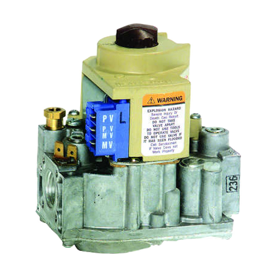
Intermittent Pilot Dual Automatic
Valve Combination Gas Controls
The VR8204 AND VR4204 Intermittent Pilot
Dual Automatic Valve Combination Gas Controls
are used in gas-fired, intermittent pilot appli-
ances. The controls include a safety shutoff, a
manual valve, two automatic operators, a pres-
sure regulator, a pilot adjustment screw and a
conduit cover (VR4204 only).
VR8204 used with S8600, S8610 and S8620 Control
Modules.
VR4204 used with 120 Vac intermittent ignition mod-
ules.
VR8204 for use with 24 Vac heating appliances and
VR4204 for use with 120 Vac heating appliances that
burn natural or manufactured gas, or liquified petroleum
(LP) gas.
Capacity rated at 150 cfh at 1 in. wc pressure drop
3
[4.2 m
/hr at 0.25 kPa].
Solenoid-operated first automatic valve opens on ther-
mostat call for heat and closes when call for heat ends.
Diaphragm-operated second automatic valve opens un-
der control of the regulator and closes if gas or power
supply is interrupted.
Two-position gas control knob has ON and OFF posi-
tions.
All adjustments and wiring connections are accessible
from top of the control.
Compact size.
Straight-through body pattern; right angle adapters avail-
able for inlet and outlet.
1/2 in. inlet and 1/2 in. outlet; adapters available for 3/8
or 3/4 in.
VR8204; VR4204
Adjustable servo regulator effectively maintains almost
constant gas output pressure under wide fluctuations in
gas supply pressure.
Inlet and outlet screens included.
Pilot filter included.
Wiring terminal block color-coded orange to indicate
intermittent pilot control.
May be installed at any angle between 0 and 90 degrees
from the upright position, including vertically.
1/4 in. male quick-connect terminals for electrical con-
nections.
0° F to 175 F° [-18° C to +79° C] temperature range
standard; -40° F to 175° F [-40° C to +79° C] available.
lnlet and outlet pressure taps provided; both taps acces-
sible from top of control.
Standard-, slow- and step-opening models available.
CONTENTS
Specifications ............................................... 2
Ordering Information .................................. 2
Installation ................................................... 4
Startup and Checkout .................................. 8
Maintenance .............................................. 10
Operation ................................................... 10
Service ........................................................ 13
G. S. • Rev. 1-94 • ©Honeywell Inc. 1994 • Form Number 68-0047-2
1
68-0047-2
Advertisement

Related Manuals for Honeywell VR8204 Series


Summary of Contents for Honeywell VR8204 Series
-
Page 1: Table Of Contents
Startup and Checkout ........8 1/2 in. inlet and 1/2 in. outlet; adapters available for 3/8 or 3/4 in. Maintenance ..........10 Operation ........... 10 Service ............13 G. S. • Rev. 1-94 • ©Honeywell Inc. 1994 • Form Number 68-0047—2 68-0047—2... -
Page 2: Specifications
If you have additional questions, need further information, or would like to comment on our products or services, please write or phone: 1. Your local Honeywell Home and Building Control Sales Office (check white pages of your phone directory). 2. Home and Building Control Division Customer Satisfaction Honeywell Inc., 1885 Douglas Drive North... - Page 3 VR8204; VR4204 SPECIFICATIONS CURRENT DRAW: MOUNTING: Can be mounted 0 to 90 degrees in any VR4204: 0.1A. direction, including vertically, from the upright position VR8204: 0.5A. of the gas control knob. ELECTRICAL CONNECTIONS: 1/4 in. male quick-con- TEMPERATURE RATING: nects. Terminal block color-coded orange. VR8204A,C,H and VR4204H: 0°...
-
Page 4: Installation
VR8204; VR4204 INSTALLATION Installation WHEN INSTALLING THIS PRODUCT… CONVERTING BETWEEN NATURAL AND LP GAS 1. Read these instructions carefully. Failure to follow WARNING them could damage the product or cause a hazardous condi- tion. FIRE OR EXPLOSION HAZARD 2. Check the ratings given in the instructions and on the CAN CAUSE PROPERTY DAMAGE, product to make sure the product is suitable for your SEVERE INJURY, OR DEATH. - Page 5 VR8204; VR4204 INSTALLATION USING ADAPTERS TO SOLVE SWING RADIUS LOCATION PROBLEMS The combination gas control is mounted in the appli- In some field service applications, it is difficult or im- ance vestibule on the gas manifold. If this is a replacement possible to thread the control onto the gas supply pipe application, mount the gas control in the same location as because of space limitations.
- Page 6 VR8204; VR4204 INSTALLATION place wrench on adapter rather than control. Refer to Figs. 5 Fig. 4—Use moderate amount of pipe com- and 6. pound. TWO IMPERFECT THREADS GAS CONTROL Fig. 5—Top view of gas control. PRESSURE REGULATOR WIRING PIPE ADJUSTMENT TERMINALS (3) (UNDER CAP SCREW) INLET...
- Page 7 VR8204; VR4204 INSTALLATION 5. Connect other end of tubing to pilot burner according Fig. 8—Wiring connections for 24 volt control to pilot burner manufacturer instructions. in intermittent ignition system with S8600. S8600 WIRING VENT Follow the wiring instructions furnished by the appli- DAMPER TH-W PLUG...
-
Page 8: Startup And Checkout
VR8204; VR4204 STARTUP AND CHECKOUT Startup and Checkout ADJUST PILOT FLAME WARNING The pilot flame should envelop 3/8 to 1 /2 in. [10 to 13 mm] of the tip of the igniter-sensor. See Fig. 10. FIRE OR EXPLOSION HAZARD To adjust pilot flame: CAN CAUSE PROPERTY DAMAGE, 1. - Page 9 VR8204; VR4204 STARTUP AND CHECKOUT CHECK AND ADJUST GAS INPUT AND BURNER b. Using screwdriver, turn inner adjustment screw IGNITION clockwise to increase or counterclock- wise to decrease gas pressure to burner. CAUTION c. Always replace cap screw and tighten firmly to prevent gas leakage.
-
Page 10: Maintenance
Contact your Honeywell sales representative The maintenance program should include regular check- to request a gas valve with corrosion resistant construction. - Page 11 VR8204; VR4204 OPERATION ward, away from the valve seat, allowing gas to flow to the VALVE POSITION DURING THERMOSTAT OFF main burner. CYCLE The valve is positioned as shown in Fig. 13 when the: STANDARD REGULATION • manual gas control knob is in the ON position. During the ON cycle, the servo pressure regulator pro- •...
- Page 12 VR8204; VR4204 OPERATION Opening is slowed because a flow restrictor in the gas. When the low pressure regulator is fully open, the high passage from the second automatic operator slows the rate pressure regulator maintains the desired full-rate outlet at which gas pressure is reduced under the second auto- pressure as described for the standard regulator.
-
Page 13: Service
VR8204; VR4204 OPERATION • SERVICE Fig. 13—Position of gas control components during burner on cycle. CONTROL SECOND AUTOMATIC SECOND KNOB VALVE OPERATOR AUTOMATIC OPERATOR SOLENOID SERVO PRESSURE REGULATOR FIRST AUTOMATIC VALVE SOLENOID SECOND AUTOMATIC OPERATOR VALVE DISC PILOT OUTLET CONTROL INLET CONTROL OUTLET... - Page 14 VR8204; VR4204 SERVICE INSTRUCTIONS TO THE HOMEOWNER TO TURN ON FURNACE FOR YOUR SAFETY, READ BEFORE OPERATING STOP! Read the safety information above. 1. The lighting sequence on this appliance is automatic; WARNING do not attempt to manually light the pilot. 2.
- Page 15 68-0047—2...
- Page 16 Home and Building Control Home and Building Control Helping You Control Your World Honeywell Inc. Honeywell Limited—Honeywell Limitée 1985 Douglas Drive North 740 Ellesmere Road Golden Valley, MN 55422 Scarborough, Ontario M1P 2V9 QUALITY IS KEY 68-0047—2 Printed in U.S.A.