Table of Contents
Advertisement
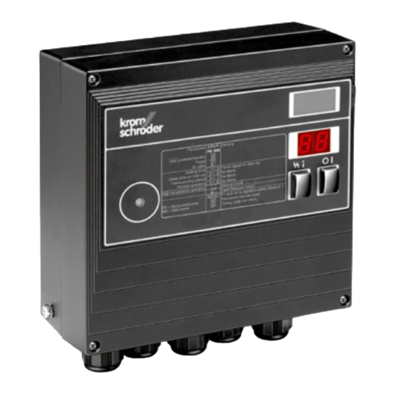
Burner control units BCU 460, BCU 465
Technical Information · GB
6 Edition 03.16l
• Replaces the local control cabinet
• For burners in intermittent operation or in continuous operation
• Flame control by UV, ionization or a further option of using the
furnace chamber temperature
• Display of the program status, unit parameters and flame signal;
Manual mode for burner adjustment and for diagnostic purposes
• Visualization and adaptation to the specific application via the
PC programming and diagnostic software BCSoft to simplify
logistics management.
Industrial & Commercial Thermal
AGA
Advertisement
Table of Contents

Related Manuals for Honeywell BCU 460


Summary of Contents for Honeywell BCU 460
-
Page 1: Burner Control Units Bcu 460, Bcu 465
Industrial & Commercial Thermal Burner control units BCU 460, BCU 465 Technical Information · GB 6 Edition 03.16l • Replaces the local control cabinet • For burners in intermittent operation or in continuous operation • Flame control by UV, ionization or a further option of using the furnace chamber temperature • Display of the program status, unit parameters and flame signal;... -
Page 2: Table Of Contents
4.4.4 Burner start-up attempts ......50 3.1.11 BCU 460..B1..E1 ........23 4.5 Behaviour during operation. - Page 3 5 Selection . . . . . . . . . . . . . . . . . . . . . . . . . . . . . . . . . . . . . . . . 66 BCU 460..L and BCU 465 ......76 5.1 Type code .
- Page 4 ..91 11.16 Probability of dangerous failure PFH 11.17 Mean time to dangerous failure MTTF ..91 BCU 460, BCU 465 · Edition 03.16l ▼ = To be continued...
-
Page 5: Application
1 Application The optional air valve control on the BCU..L assists the furnace control for cooling, purging and capacity con- The burner control units BCU 460 and BCU 465 control, trol tasks. ignite and monitor gas burners for intermittent or con- The BCU 465..L is fitted with air flow monitoring and pre-... - Page 6 Hardening fur- the system efficiently. nace with lots of industrial burners located side-by- side BCU 460, BCU 465 · Edition 03.16l...
-
Page 7: Examples Of Application
The burner starts at low- fire rate, and a controller controls the burner capacity via the butterfly valve for air after the operating state has BCU 460 been signalled. µC VG..L DK+GT BCU 460, BCU 465 · Edition 03.16l... -
Page 8: Bcu 460
Application 1 .1 .2 BCU 460 . .L: Two-stage- controlled burner Control: ON/OFF or ON/HIGH/ LOW/OFF intermittent operation. The BCU supports the cooling and purging processes. The burner starts at low-fire rate. When the L1, N, PE operating state is reached, the BCU advises the control unit. -
Page 9: Bcu 465
The gas/air mixture is adjusted to the requirements of the applications using the differ- µC ing parameters of pre- and post- ventilation. BCU 465..L VG..L BICR VR..R BCU 460, BCU 465 · Edition 03.16l... -
Page 10: Bcu 465
µC flow in the air supply line or in the flue gas exhaust. L1, N, PE BCU 465..L ▼ VG..L BICR VR..R µC BCU 465..L VG..L BICR VR..R BCU 460, BCU 465 · Edition 03.16l... -
Page 11: Bcu 460
Application 1 .1 .5 BCU 460 . .B1 for PROFIBUS DP The bus system transfers the con- trol signals for starting, resetting L1, N, PE and for controlling the air valve from the control system (PLC) to the BCU..B1. In the opposite direction... -
Page 12: Certification
Eurasian Customs Union Meets the requirements of the – Low Voltage Directive (2006/95/EC), – EMC Directive (2004/108/EC). The products BCU 460 and BCU 465 meet the techni- ANSI/CSA approved cal specifications of the Eurasian Customs Union. American National Standards Institute/Canadian Standards Association – ANSI Z21.20/CSA C22.2, No. -
Page 13: Function
7 8 9 7 8 9 3 Function 3 .1 Connection diagrams 3 .1 .1 BCU 460 . .E1 For cable selection and wiring, see page 67 (Project planning information). For the explanation of symbols, see page 88 (Leg- end). -
Page 14: Bcu 460
N (L2) 7 8 9 7 8 9 3 .1 .2 BCU 460 For cable selection and wiring, see page 67 (Project planning information). For the explanation of symbols, see page 88 (Leg- end). BCU 460, BCU 465 · Edition 03.16l... -
Page 15: Bcu 465
7 8 9 7 8 9 3 .1 .3 BCU 465 . .E1 For cable selection and wiring, see page 67 (Project planning information). For the explanation of symbols, see page 88 (Leg- end). BCU 460, BCU 465 · Edition 03.16l... -
Page 16: Bcu 465
N (L2) 7 8 9 7 8 9 3 .1 .4 BCU 465 For cable selection and wiring, see page 67 (Project planning information). For the explanation of symbols, see page 88 (Leg- end). BCU 460, BCU 465 · Edition 03.16l... -
Page 17: Bcu 465T
= BCU 465T..D3 ** = BCU 465T..O 3 .1 .5 BCU 465T . .E1 For cable selection and wiring, see page 67 (Project planning information). For the explanation of symbols, see page 88 (Leg- end). BCU 460, BCU 465 · Edition 03.16l... -
Page 18: Bcu 465T
= BCU 465T..D3 ** = BCU 465T..O 3 .1 .6 BCU 465T For cable selection and wiring, see page 67 (Project planning information). For the explanation of symbols, see page 88 (Leg- end). BCU 460, BCU 465 · Edition 03.16l... -
Page 19: Bcu 460
12 11 10 7 8 9 7 8 9 3 .1 . 7 BCU 460 . .P . .E1 with industrial plug connector For cable selection and wiring, see page 67 (Project planning information). For the explanation of symbols, see page 88 (Leg- end). -
Page 20: Bcu 460
12 11 10 7 8 9 7 8 9 3 .1 .8 BCU 460 . .P with industrial plug connector For cable selection and wiring, see page 67 (Project planning information). For the explanation of symbols, see page 88 (Leg- end). -
Page 21: Bcu 465
3 .1 .9 BCU 465 . .P . .E1 with industrial plug connector For cable selection and wiring, see page 67 (Project planning information). For the explanation of symbols, see page 88 (Leg- end). BCU 460, BCU 465 · Edition 03.16l... -
Page 22: Bcu 465
7 8 9 3 .1 .10 BCU 465 . .P with industrial plug connector For cable selection and wiring, see page 67 (Project planning information). For the explanation of symbols, see page 88 (Leg- end). BCU 460, BCU 465 · Edition 03.16l... -
Page 23: Bcu 460
N (L2) 7 8 9 7 8 9 BCU..B1/1 PROFIBUS-DP 3 .1 .11 BCU 460 . .B1 . .E1 For cable selection and wiring, see page 67 (Project planning information). For the explanation of symbols, see page 88 (Leg- end). -
Page 24: Bcu 460
N (L2) 7 8 9 7 8 9 BCU..B1/1 PROFIBUS-DP 3 .1 .12 BCU 460 . .B1 For cable selection and wiring, see page 67 (Project planning information). For the explanation of symbols, see page 88 (Leg- end). BCU 460, BCU 465 · Edition 03.16l... -
Page 25: Bcu 465
7 8 9 BCU..B1/1 PROFIBUS-DP 3 .1 .13 BCU 465 . .B1 . .E1 For cable selection and wiring, see page 67 (Project planning information). For the explanation of symbols, see page 88 (Leg- end). BCU 460, BCU 465 · Edition 03.16l... -
Page 26: Bcu 465
7 8 9 BCU..B1/1 PROFIBUS-DP 3 .1 .14 BCU 465 . .B1 For cable selection and wiring, see page 67 (Project planning information). For the explanation of symbols, see page 88 (Leg- end). BCU 460, BCU 465 · Edition 03.16l... -
Page 27: Bcu 465T
** = BCU 465T..O PROFIBUS-DP 3 .1 .15 BCU 465T . .B1 . .E1 For cable selection and wiring, see page 67 (Project planning information). For the explanation of symbols, see page 88 (Leg- end). BCU 460, BCU 465 · Edition 03.16l... -
Page 28: Bcu 465T
** = BCU 465T..O PROFIBUS-DP 3 .1 .16 BCU 465T . .B1 For cable selection and wiring, see page 67 (Project planning information). For the explanation of symbols, see page 88 (Leg- end). BCU 460, BCU 465 · Edition 03.16l... -
Page 29: Bcu
Function 3 .2 BCU . .P with 16-pin industrial plug connector The burner control units BCU 460..P and BCU 465..P can be supplied with an industrial plug connector (pur- suant to VDE 0627). This 16-pin plug connector en- sures fast connecting or disconnecting of units without any additional wiring required. -
Page 30: Profibus Dp
PROFIBUS 1– 6 or via a separate cable to terminal 22. The purging pro- cess must be monitored by further measures, e.g. flow monitoring. BCU 460, BCU 465 · Edition 03.16l... -
Page 31: Bcsoft
– DP Slaves The devices which transmit input information from the periphery to the master and which issue output information from the master to the periphery are re- BCU 460, BCU 465 · Edition 03.16l... -
Page 32: Network Technology
BCU..B1. The GSD file can also Reserved be ordered at www.docuthek.com. The steps required Reserved to copy the file are described in the instructions for the Reserved automation system. ▼ BCU 460, BCU 465 · Edition 03.16l... - Page 33 No more than three repeaters should be connected in series. The specified ranges relate to bus cable type A (two- core, shielded and twisted), e.g. Siemens, Order No.: 6XV1830-0EH10, or Lapp cable unitronic, Order No.: 2170-220T. BCU 460, BCU 465 · Edition 03.16l...
-
Page 34: Bcu 460 Program Sequence
Valve V2 starts to elapse (P20) opens and the operation signalling contact between terminals 16 and 17 closes. If no flame detected: ▼ max. 3 start-up attempts or fault lock-out BCU 460, BCU 465 · Edition 03.16l Flame proving period t... - Page 35 (P21) If the flame fails during operation, either an immediate fault lock-out or a restart occurs. This procedure can be set via the optical interface (parameter 12, “Burner restart”). BCU 460, BCU 465 · Edition 03.16l...
-
Page 36: Bcu 465 Program Sequence
V1 and ignites the burner. The Min. burner pause time t ignition time t is constant. running once again (P21) ▼ If parameter P15 = 0: flame simulation check BCU 460, BCU 465 · Edition 03.16l Pre-ventilation time t running (P37) - Page 37 The BCU can also be operated in fault lock-out Manual mode for start-up. Operation signalling contact closes and ▼ V2 opens In the event of flame failure or air flow failure: restart or fault lock-out BCU 460, BCU 465 · Edition 03.16l...
- Page 38 If the flame or air flow fails during operation, either an immediate fault lock-out or a restart occurs. This procedure can be set via the optical interface (parameter 12, “Burner restart”). BCU 460, BCU 465 · Edition 03.16l...
-
Page 39: Program Status And Fault Messages
Fault Position indicator in position X No air flow in position X High temperature operation Bus fault ▼ BCU 460, BCU 465 · Edition 03.16l... - Page 40 Timing cycle too short In Manual mode, two dots will blink on the display in program status 01– 04 . * FS = input/output, safety circuit, NFS = input/output, control system. BCU 460, BCU 465 · Edition 03.16l...
-
Page 41: Parameters
Manual mode limited to 5 minutes 0; 1 UVS check 0; 1 Low fire over run-time t after a controlled shut-down 0; 5; 15; 25 s ** ** ** ▼ BCU 460, BCU 465 · Edition 03.16l... -
Page 42: Scanning The Parameters
Reset/Information button (for 2 seconds). In the event of a fault, the BCU halts the program run, the display blinks and it then displays the cause of the fault in coded form. BCU 460, BCU 465 · Edition 03.16l... -
Page 43: Flame Control
“own” burner is de- tected. The measured flame signal of the system’s “own” burner should be at least 3 µA (empirical value) higher than the set switch-off threshold. BCU 460, BCU 465 · Edition 03.16l... -
Page 44: High Temperature Operation In The Case Of Bcu
The precondition for this operating mode is that an ex- ternal flame supervision device ensures the presence of the flame in fail-safe manner indirectly via the tempera- ture. For this purpose, we recommend a safety temper- BCU 460, BCU 465 · Edition 03.16l... - Page 45 (recommended in the case of eration is deactivated, the burner control unit performs UV control with UVS). a fault lock-out, regardless of parameter 33. ϑ 16-17 18-19 Note the requirements of the Standards! BCU 460, BCU 465 · Edition 03.16l...
-
Page 46: Uvs Check
This process is controlled independently by the BCU and therefore it must be checked whether the industrial process permits the pause in heat supply it creates. BCU 460, BCU 465 · Edition 03.16l... -
Page 47: Behaviour In Start-Up Position/Standby
The flame simulation check of the burner is active until What is an extraneous signal? valve V1 is enabled. An extraneous signal is an incorrect signal which is detected as a flame signal out of sequence. If the BCU BCU 460, BCU 465 · Edition 03.16l... -
Page 48: Position Indicator Input On Bcu 465T
In standby, the switch must be closed. During start-up and operation, the switch must be open. This ensures that valve V1 is open or closed. BCU 460, BCU 465 · Edition 03.16l... -
Page 49: Minimum Burner Pause Time T Bp
The time should be set such that the system can be moved to ignition position, i.e. air valves or butterfly valves can be closed and, possibly, gas can be flared off, before a restart occurs. BCU 460, BCU 465 · Edition 03.16l... -
Page 50: Behaviour During Start-Up
This time is independent of the pre-ventilation curs or up to two further start-up attempts occur. The time. required functions and, if applicable, the number of start-up attempts must be specified when ordering. ▼ BCU 460, BCU 465 · Edition 03.16l... - Page 51 After the last programmed start-up attempt has been completed, the burner con- trol unit conducts a fault lock-out. The display blinks and shows the cause of the fault. BCU 460, BCU 465 · Edition 03.16l...
-
Page 52: Behaviour During Operation
4 .5 .2 Fault lock-out or restart Parameter 12 This parameter determines whether the BCU starts a one-off restart or performs an immediate fault lock-out for the burner after an installation fault (flame failure or failure of air flow). BCU 460, BCU 465 · Edition 03.16l... -
Page 53: Immediate Fault Lock-Out After Installation Fault
The BCU cannot be reset by mains failure. The fault operating phases). In this case, it must be ensured that signalling contact does, however, open as soon as the the program sequence started by the BCU matches the mains voltage fails. application. BCU 460, BCU 465 · Edition 03.16l... -
Page 54: Program Status On Last Fault
Example: the unit indicates that the safety interlocks have been interrupted with a blinking 51 . Parameter 03 can now be used to scan in what program status the BCU was when the fault was detected. BCU 460, BCU 465 · Edition 03.16l... -
Page 55: Air Valve Control On Bcu
(purging has priority). The display indicates P0 . On BCUs without power management, input 22 and in- put 5 (safety interlocks) must be activated for purging, see from page 13 (Connection diagrams). BCU 460, BCU 465 · Edition 03.16l... -
Page 56: Cooling In Start-Up Position/Standby
These settings are required on burners on which the gas/air ratio is controlled by a pneumatic air/gas ratio control system link and which also need to be started at low fire, e.g. on two-stage-controlled burners, see page BCU 460, BCU 465 · Edition 03.16l... -
Page 57: (Even During Start-Up)
V2. 4 .6 .5 Air valve opens with valve V1 It can be activated externally via input 23 for cooling the burner in the start-up position/standby. ϑ 16-17 18-19 BCU 460, BCU 465 · Edition 03.16l... -
Page 58: Low Fire Over Run-Time T
Flame control is still operational. Can be used only in the case of a pneumatic air/gas ra- tio control system and On/Off control. Its must be ensured that no excess gas occurs. BCU 460, BCU 465 · Edition 03.16l... -
Page 59: Behaviour Of The Air Valve After A Fault Lock-Out
Parameter 32 = 0: The air valve is closed in the event of a fault. It cannot be activated externally. Parameter 32 = 1: The air valve can be activated exter- nally by input 23 even during a fault, e.g. for cooling. BCU 460, BCU 465 · Edition 03.16l... -
Page 60: Extended Air Control With Bcu 465
BCU performs a fault lock-out after ex- piry of a delay time (as long as the flame simulation de- ). Fault message: 0 , “no flow” state check lay time t failed. BCU 460, BCU 465 · Edition 03.16l... -
Page 61: Pre-Ventilation Time T Vl Before Start-Up
“no flow” state check have been conducted successfully, the air valve is opened. Start-up of the burner commences as usual with no interruption of the air after expiry of the pro- grammable pre-ventilation time t BCU 460, BCU 465 · Edition 03.16l... - Page 62 If the HIGH signal is not applied within a specified testing time (as long as the safety time on start-up t the BCU performs a fault lock-out. Fault message: no air pressure in operating state. BCU 460, BCU 465 · Edition 03.16l...
-
Page 63: Air Flow Monitoring During Operation (Bcu 465
18-19 The air valve remains open for the programmed time after the start-up signal (ϑ) has been deactivated. The burner control unit closes the air valve after expiry of the post-ventilation time t BCU 460, BCU 465 · Edition 03.16l... -
Page 64: Pre-Ventilation Time After Safety Shut-Down
Parameter 41 = 1: The pre-ventilation time is activated is not implemented by a central control system but by after a reset with the start-up signal (ϑ). the BCU 465. See also parameters 40 and 41. BCU 460, BCU 465 · Edition 03.16l... -
Page 65: Manual Mode
Manual mode can always be terminated independently of parameter 34 by switching off the BCU. On units with air valve control, the air valve can be opened and closed repeatedly by pressing the button during operation. BCU 460, BCU 465 · Edition 03.16l... -
Page 66: Selection
Preparation for UV sensor for continuous operation UVD 1 Additional signal distribution For PROFIBUS DP 9-pin D-Sub bus plug connector Power management via phase (L1) * If “none”, this specifi cation is omitted. Please quote the default parameter settings when ordering. BCU 460, BCU 465 · Edition 03.16l... -
Page 67: Project Planning Information
We recommend using 7.5 kV ignition transformers on (Accessories). burners with star electrodes. Cable length for integrated ignition. max. 5 m (16.4 ft). Avoid external electrical interference. The longer the ig- nition cable, the lower the ignition capacity. BCU 460, BCU 465 · Edition 03.16l... -
Page 68: Calculating The Safety Time T Sa
Project planning information 6 .3 Calculating the safety time t BCU 460, BCU 465 · Edition 03.16l... -
Page 69: Minimum Burner On Time
5 from the voltage supply. If the safety interlock is interrupted, the display shows a blinking 51 to indicate a fault. BCU 460, BCU 465 · Edition 03.16l... -
Page 70: Reset
In accordance with EN 746-2, a maximum of three function cannot be remedied by changing the method start-ups are permitted in specific cases if the safety of of activation. the installation is not impaired. Note the requirements of the Standards! BCU 460, BCU 465 · Edition 03.16l... -
Page 71: Fault Signalling
7,5-12/100 7,5-12/100 7,5-12/100 7,5-20/33 7,5-20/33 7,5-20/33 Screw on the closed unit to the rear with 4 self-tapping screws (enclosed). Otherwise, mount with external securing bars or the fastening set, see page 81 (Accessories). BCU 460, BCU 465 · Edition 03.16l... -
Page 72: Wiring
A BCU without power management may not be re- placed with a BCU with power management (BCU..E1). The reverse also applies, i.e. a BCU..E1 may not be re- placed with a BCU without power management. BCU 460, BCU 465 · Edition 03.16l... -
Page 73: Profibus Dp
PROFIBUS plug connector. Ensure an equipotential bond between the different slaves and masters. 6 .17 .3 EMC To achieve a high immunity of the system against elec- tromagnetic interference radiation, a shielded data BCU 460, BCU 465 · Edition 03.16l... -
Page 74: Status And Fault Messages For Profibus Dp
Start-up without flame signal, main burner Fault Position indicator during safety time Fault Air supply during safety time Flame proving period, main burner Flame failure during flame proving period, main burner BCU 460, BCU 465 · Edition 03.16l... - Page 75 Internal error/negative flame current Display on BCU..L upon activation of the air valve during program step x ** FS = input/output, safety circuit, NFS = input/output, control system = standard, = available BCU 460, BCU 465 · Edition 03.16l...
-
Page 76: Third Gas Valve (Can Be Shut Down) On
6 .18 Third gas valve (can be shut down) on The following application describes a two-stage-con- trolled burner without a pneumatic air/gas ratio control BCU 460 . .L and BCU 465 system. V2 and the air valve are activated simultane- Units with air valve control have an additional contact ously. -
Page 77: Bcu Switched Off
EN 50156, it does allow the burner to be isolated functionally from the central control system. This func- tion is required for manual operation and, in the case of PROFIBUS units, to switch off the unit without causing bus errors. BCU 460, BCU 465 · Edition 03.16l... -
Page 78: Changing Parameters
Document changed parameters in BCSoft using the protocol function and enclose the protocol with the plant documentation. If a replacement is ordered for a BCU with changed pa- rameters, refer to the protocol for details. BCU 460, BCU 465 · Edition 03.16l... -
Page 79: Flame Control
24 hours. This can be programmed by setting pa- rameter 35 to 1. Further information can be found in brochure UVS at www.docuthek.com. BCU 460, BCU 465 · Edition 03.16l... -
Page 80: Via The Temperature In High Temperature
DI input being activated, burner con- trol units BCU..D2 (D3) do not evaluate the flame signal. The safety function of the burner control unit’s flame control is deactivated during this operating phase. BCU 460, BCU 465 · Edition 03.16l... -
Page 81: Accessories
4.001, available from the PUO. – M. Popp, The New Rapid Way to PROFIBUS DP, a text- book for system operators. – M. Popp, PROFIBUS DP Principles, Tips and Tricks for Users. – www.profibus.com BCU 460, BCU 465 · Edition 03.16l... -
Page 82: Bcsoft
Les informations figurant sur la plaque signalétique ne sont plus valables dans leur intégralité. Veuillez vous référer directement aux paramètres actualisés. With USB interface, cable length 3 m, including BCSoft CD-ROM. Order No.: 74960437. BCU 460, BCU 465 · Edition 03.16l... -
Page 83: External Securing Bar
Order No.: 74960414 8 .8 Radio interference suppressed electrode plugs Angle plug, 4 mm, interference-suppressed, Order No. 04115308. Straight plug, 4 mm, interference-suppressed, Order No. 04115307. Straight plug, 6 mm, interference-suppressed, Order No. 04115306. BCU 460, BCU 465 · Edition 03.16l... -
Page 84: Technical Data
▼ and 12 mm. Input voltage of signal inputs: 115 V AC 230 V AC Signal “1” 80 – 126.5 160 – 253 Signal “0” 0 – 20 0 – 40 Input current of signal inputs: Signal “1”: typ. 2 mA BCU 460, BCU 465 · Edition 03.16l... -
Page 85: Bcu
Enclosure: IP 54 pursuant to IEC 529. Baud rate detection: automatic. Weight: approx. 5 kg depending on version. Min. cycle time: 0.1 ms. Diagnostic bytes: 6 (DP Standard). Parameter bytes: 7 (DP Standard). BCU 460, BCU 465 · Edition 03.16l... -
Page 86: Safety-Specific Characteristic Values
No characteristic values are available for flame control with UVS sensor. For flame control with UVD sensor, safety-specific characteristic values are available for the Safety Integ- rity Level SIL. Further information can be found in TI UVD 1 at www.docuthek.com. BCU 460, BCU 465 · Edition 03.16l... -
Page 87: Control Elements
Electrical connection via plug-in connection terminals (2.5 mm ) and plug-in cable glands. The latter can be removed in order to facilitate installation. When install- ing, ensure that there is sufficient space to open the BCU. BCU 460, BCU 465 · Edition 03.16l... -
Page 88: Legend
Safety time on start-up 3 s, 5 s or 10 s Safety time during operation < 1 s or < 2 s Ignition time 2 s, 3 s or 6 s Flame simulation delay time 25 s Flame proving period 0 – 25 s BCU 460, BCU 465 · Edition 03.16l... -
Page 89: Glossary
V1 and the ignition trans- former and the burner is ignited. The duration of the ignition time is either 2, 3 or 7 seconds (depending on safety time t selected). BCU 460, BCU 465 · Edition 03.16l... -
Page 90: Safety Time During Operation T Sb
In the event of a fault lock-out, all valves and the igni- tion transformer are disconnected from the electrical power supply, and a fault is signalled. Resetting must ϑ take place manually following a fault lock-out. 7 8 9 7 8 9 BCU 460, BCU 465 · Edition 03.16l... -
Page 91: Continuous Operation
For example, diagnos- MTTF tic coverage could exist for sensors and/or logic system and/or final elements. Unit: %. Expectation of the mean time to dangerous failure from EN ISO 13849-1:2008 from EN ISO 13849-1:2008 BCU 460, BCU 465 · Edition 03.16l... - Page 92 Strotheweg 1 · 49504 Lotte (Büren) Germany Tel +49 541 1214-0 We reserve the right to make technical Fax +49 541 1214-370 modifications in the interests of progress. info@kromschroeder.com Copyright © 2016 Elster GmbH www.kromschroeder.com All rights reserved. BCU 460, BCU 465 · Edition 03.16l...