
Related Manuals for McIntosh MC 2120


Summary of Contents for McIntosh MC 2120
-
Page 1: Service
5/10/2017 THE MCINTOSH MC 2120 SOLID STATE STEREO POWER AMPLIFIER R e a d i n g Time: 29 M i n u t e s Price $1.25 Digitized in Heiloo Netherland... -
Page 2: Installation
www.freeservicemanuals.info 5/10/2017 Digitized in Heiloo Netherland... -
Page 3: Table Of Contents
5/10/2017 Your MC 2120 Stereo Power Amplifier will give you many years of pleasant and satisfactory performance. If you Contents have any questions, please contact: CUSTOMER SERVICE Mclntosh Laboratory Inc. SERVICE ..1 2 Chambers Street... -
Page 4: How To Connect
5/10/2017 available from the MC 2120, be sure to use large diameter INPUT speaker leads. In all cases, the leads to and from the STEREO OR TWIN AMPLIFIER OPERATION speaker should be twin conductor or twisted together. Use Use shielded cables to connect the signal from the pre- lamp cord, bell wire, or wire with similar type of insulation amplifier or signal source to the power amplifier input. - Page 5 AC POWER the output impedance tap, then neither the signal nor the The MC 2120 operates on 120 volts 50/60 Hz. The a u x - amplifier will be harmed but the power available is limited. iliary AC OUTLET on the MC 2120 is not fused or switched.
- Page 6 www.freeservicemanuals.info 5/10/2017 Stereophonic Connections PROGRAM SOURCE RIGHT SPEAKER MUST BE IN STEREO STEREO POSITION FOR STEREO PROGRAMS MODE SWITCH LEFT SPEAKER MONO Digitized in Heiloo Netherland...
- Page 7 www.freeservicemanuals.info 5/10/2017 Monophonic Connections PROGRAM SOURCE STEREO CONNECT FOR MONO USE ONLY WHEN THE MODE MODE SWITCH IS IN MONOPOSITION SWITCH MONO Digitized in Heiloo Netherland...
-
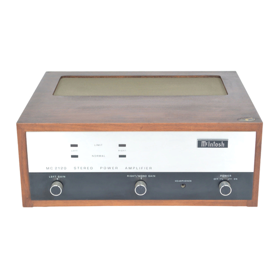
Page 8: Front Panel Information
Turn the control clockwise to increase the volume. MONO With the output of MC 2120 connected for monophonic operation and the rear panel MODE SWITCH in MONO the volume is controlled by the RIGHT/MONO GAIN control only. - Page 9 ON position. Be sure at the input in excess of its rating. Because the limit in- the AC cord of the MC 2120 is plugged into the controlled dicator circuit can show an overload condition as short as outlets on the rear of the preamplifier control center.
-
Page 10: Rear Panel Information
Recommended operations is with AC POWER the POWER GUARD switch in the NORMAL position at all The MC 2120 is rated for 120 volts, 50/60 hertz. It uses times. 50 watts when there is no signal output and 460 watts MODE SWITCH with both channels delivering rated power. -
Page 11: Performance Limits And Ratings
Hz, both channels operating fection permitted for Mclntosh instrument. We promise you that the MC 2120 you buy must be capable per- MONO formance at or exceeding these limits or you get your 0.1% maximum harmonic distortion at any money back. -
Page 12: Performance Charts
www.freeservicemanuals.info 5/10/2017 Performance Charts Per Channel Both Channels Operating HARMONIC DISTORTION AT RATED OUTPUT FREQUENCY RESPONSE AT 1 WATT OUTPUT POWER BANDWIDTH AT 0.1% THD Digitized in Heiloo Netherland... - Page 13 www.freeservicemanuals.info 5/10/2017 OUTPUT SIGNAL WAVEFORM SHOWING ACTION OF POWER GUARD TO ELIMINATE OUTPUT SIGNAL CLIPPING. AMPLIFIER INPUT IS OVERDRIVEN BY 20 dB FOR BOTH OSCILLOGRAM TRACES. INTERMODULATION DISTORTION VS. POWER OUTPUT HARMONIC DISTORTION VS. POWER OUTPUT Digitized in Heiloo Netherland...
-
Page 14: Technical Description
5/10/2017 Technical Description The MC 2120 has transient free turn on and turn off char- INPUT AMPLIFIER acteristics. This is because the output of the amplifier is Separate input amplifiers are used for the right and switched by a heavy duty relay to the output autotrans- left channels. - Page 15 www.freeservicemanuals.info 5/10/2017 The input waveform and the output waveform are com- pared in an integrated circuit differential amplifier. Any differences, due to distortion of the output waveform, are converted to a control voltage. This control voltage is applied differentially to a high gam operational amplifier where it is amplified about 100 times.
-
Page 16: Block Diagram
www.freeservicemanuals.info 5/10/2017 Digitized in Heiloo Netherland... - Page 17 www.freeservicemanuals.info 5/10/2017 Digitized in Heiloo Netherland...
- Page 18 5/10/2017 MCINTOSH LABORATORY INC. 2 CHAMBERS ST., BINGHAMTON, N. Y. 13903 607-723-3512 Design subject to change without notice. Printed in U.S.A. 038-921 Digitized in Heiloo Netherland...