Suzuki SWIFT Owner's Manual
Hide thumbs
Also See for SWIFT:
- User manual (558 pages) ,
- Owner's manual (480 pages) ,
- Owner's manual (199 pages)
Table of Contents
Advertisement
Quick Links
ENGLISH
SERVICE STATION INFORMATION
Fuel recommendation:
See page 1-1
Engine oil recommendation:
Classification: API SL, SM or SN
Viscosity: SAE 0W-16, 0W-20, 5W-30
For further details, see "Engine oil and filter" in the
"INSPECTION AND MAINTENANCE" section.
Part No. 99011-57RK0-14E January, 2018
Suzuki Red: Magenta 100%, Yellow 100%
Suzuki Blue: Cyan 100%, Magenta 70%
Takumi Blue: Cyan 100%, Black 85%
Black
14.0 mm
Brake and clutch fluid:
DOT3 or SAE J1703
CVT fluid:
SUZUKI CVTF GREEN-2
Tire cold pressure:
See the "Tire Information Label" located on the
driver's door lock pillar.
Printed in Thailand
OWNER'S MANUAL
Keep With Vehicle At All Times.
Contains Important Information
On Safety, Operation & Maintenance.
Advertisement
Chapters
Table of Contents

Related Manuals for Suzuki SWIFT


Summary of Contents for Suzuki SWIFT
- Page 1 Keep With Vehicle At All Times. Contains Important Information On Safety, Operation & Maintenance. Part No. 99011-57RK0-14E January, 2018 Printed in Thailand Suzuki Red: Magenta 100%, Yellow 100% Suzuki Blue: Cyan 100%, Magenta 70% Takumi Blue: Cyan 100%, Black 85% Black...
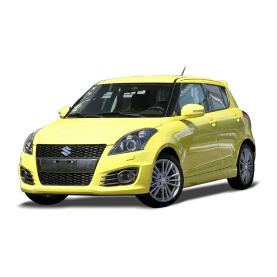
- Page 2 NOTE: The illustrated model is one of the SWIFT series. Copyright © 2018 All Rights Reserved No part of this document may be reproduced or transmitted in any form or by any means, electronic or mechanical, for any purpose, without the express written permission of Suzuki Motor Corporation.
- Page 3 Please read this manual carefully cial information, the symbol and the tion in this manual and your vehicle. before operating your new SUZUKI vehicle words WARNING, CAUTION, NOTICE SUZUKI MOTOR CORPORATION and review the manual from time to time. It and NOTE have special meanings.
- Page 4 CB (Citizen’s Band) radios or any other wireless transmit- ters may cause electronic interfer- ence with your vehicle’s ignition system, resulting in vehicle perfor- mance problems. Consult an autho- rized SUZUKI dealer or qualified service technician for advice. 57RK0-14E...
- Page 5 INTRODUCTION Thank you for choosing SUZUKI product and welcome to our growing family. Your choice was a wise one; SUZUKI products have great value that will give you driving pleasure for years. This owner’s manual was prepared to give you a safe, enjoyable, and trouble-free experience with your SUZUKI vehicle. In this manual, you will learn about the vehicle’s operation, its safety features and maintenance requirements.
- Page 6 A wide variety of non-genuine replacement parts and accessories for SUZUKI vehicles are currently available in the market. Using these parts and accessories can affect the vehicle performance and shorten its useful life. Therefore, installation of non-genuine SUZUKI parts and accessories is not covered under warranty.
- Page 7 SERVICE STATION GUIDE 1. Engine hood release handle (see section 5) 2. Engine coolant (see section 7) 3. Windshield washer fluid (see section 7) 4. Engine oil dipstick <Yellow> (see section 7) 5. CVT fluid dipstick <Orange> (see section 7) 6.
- Page 8 MEMO 57RK0-14E...
-
Page 9: Table Of Contents
TABLE OF CONTENTS FUEL RECOMMENDATION BEFORE DRIVING OPERATING YOUR VEHICLE DRIVING TIPS OTHER CONTROLS AND EQUIPMENT VEHICLE LOADING AND TOWING INSPECTION AND MAINTENANCE EMERGENCY SERVICE APPEARANCE CARE GENERAL INFORMATION SPECIFICATIONS INDEX 57RK0-14E... - Page 10 ILLUSTRATED TABLE OF CONTENTS EXTERIOR, FRONT EXAMPLE 1. Engine hood (P.5-2) 2. Windshield wipers (P.2-92) 3. Frame (towing) hook (P.5-11) 4. Position lights & Daytime running lights (D.R.L.) (if equipped) (P.2-89, 2-90) 5. Front fog lights (if equipped) (P.2-90, 7-37) 6.
- Page 11 ILLUSTRATED TABLE OF CONTENTS EXTERIOR, REAR EXAMPLE 1. Radio antenna (P.5-26) 2. High-mount stop light (P.7-39) 3. Rear window wiper (P.2-94) 4. Fuel filler cap (P.5-1) 5. Rear combination lights (P.7-37) 6. Tailgate (P.2-4) 7. License plate lights (P.7-39) 57RK084 57RK0-14E...
- Page 12 ILLUSTRATED TABLE OF CONTENTS INTERIOR, FRONT EXAMPLE 1. Front passenger’s front air bag (P.2-42) 2. Power window controls (P.2-18)/ Remote mirror control switch (if equipped) (P.2-21)/ Outside rearview mirror folding switch (if equipped) (P.2-22) 3. Fuses (P.7-30) 4. Glove box (P.5-7) 5.
- Page 13 ILLUSTRATED TABLE OF CONTENTS 1. Hands-free microphone (if equipped) VIEW A EXAMPLE (P.5-53) 2. Front interior light (P.5-5, 7-39) 3. Sun visor (P.5-4) 4. Inside rearview mirror (P.2-20) 57RK002 57RK0-14E...
- Page 14 ILLUSTRATED TABLE OF CONTENTS 1. Remote audio controls (if equipped) VIEW B EXAMPLE (P.5-64) 2. Driver’s front air bag (P.2-42) 3. Cruise control switches (if equipped) (P.3-25) 4. Lighting control lever (P.2-89)/ Turn signal control lever (P.2-91)/ Front fog light switch (if equipped) (P.2-90) 5.
- Page 15 ILLUSTRATED TABLE OF CONTENTS 1. Hazard warning switch (P.2-92) VIEW C EXAMPLE 2. Theft deterrent alarm system (if equipped) (P.2-14)/ Theft deterrent light (if equipped) (P.2-18) 3. Windshield wiper and washer lever (P.2-92)/ Rear window wiper/washer switch (P.2-94) 4. Instrument cluster (P.2-52, 2-61)/ Information display (P.2-55, 2-64) 5.
- Page 16 ILLUSTRATED TABLE OF CONTENTS INTERIOR, REAR EXAMPLE 1. Seat belts (P.2-26) 2. Assist grips (if equipped) (P.5-7) 3. Side curtain air bags (if equipped) (P.2-46) 4. Rear seats (P.2-24) 52RM00071 57RK0-14E...
- Page 17 ILLUSTRATED TABLE OF CONTENTS LUGGAGE EXAMPLE COMPARTMENT 1. Luggage compartment cover (if equipped) (P.5-11) 2. Luggage compartment light (if equipped) (P.5-5, 7-39) 3. Luggage compartment hook (P.5-10) 4. Jack handle (P.8-1) 5. Towing hook (P.5-11) 6. Wheel wrench (P.8-1) 7. Flat tire repair kit (P.8-6) 8.
- Page 18 ILLUSTRATED TABLE OF CONTENTS MEMO 57RK0-14E...
-
Page 19: Fuel Recommendation
FUEL RECOMMENDATION FUEL RECOMMENDATION Fuel recommendation ............1-1 65D394 57RK0-14E... - Page 20 FUEL RECOMMENDATION Gasoline-ethanol blends Fuel recommendation NOTICE Blends of unleaded gasoline and ethanol (grain alcohol), also known as gasohol, are Be careful not to spill fuel containing commercially available in certain areas. alcohol while refueling. If fuel is Blends of this type may be used in your EXAMPLE spilled on the vehicle body, wipe it up vehicle if they are no more than 20% etha-...
-
Page 21: Before Driving
BEFORE DRIVING BEFORE DRIVING Supplemental restraint system (air bags) ......2-41 Instrument cluster (Type A) (if equipped) ......2-52 Speedometer ............... 2-53 Tachometer ................2-53 Fuel gauge ................2-53 Brightness control .............. 2-54 Information display ............. 2-55 Instrument cluster (Type B) (if equipped) ......2-61 Speedometer ............... -
Page 22: Keys
Ask an on a metal tag provided with the keys or on authorized SUZUKI dealer to have the sys- the keys. Keep the tag in a safe place. If tem inspected. -
Page 23: Door Locks
• If you lose your immobilizer ignition key (3) Front or remote controller, ask an authorized (4) Rear SUZUKI dealer as soon as possible to deactivate the lost one, and to make a To lock the driver’s door from the outside of new key or remote controller. - Page 24 BEFORE DRIVING To unlock the driver’s door from the out- key in the driver’s door lock and turn the Central door locking system side of the vehicle, insert the key and turn top of the key toward the rear of the vehi- (if equipped) the top of the key toward the rear of the cle twice.
- Page 25 BEFORE DRIVING NOTE: Child-proof locks (rear door) Tailgate • If your vehicle is equipped with the key- less entry system or keyless push start system, you can also lock or unlock all EXAMPLE WARNING doors by operating the transmitter or Always check that the tailgate is remote controller.
- Page 26 If the tailgate cannot be unlatched by push- ing the unlatch switch (1), have the vehicle inspected by an authorized SUZUKI dealer. CAUTION Check that there is no one near the 52RM20640...
-
Page 27: Keyless Push Start System Remote Controller / Keyless Entry System Transmitter (If Equipped)
• If radio wave interference is a con- cern, have the function of the antenna(s) disabled by an autho- rized SUZUKI dealer. 52RM20050 Your vehicle is equipped with either a key- less push start system remote controller (Type A) or a keyless entry system trans- mitter (Type B). - Page 28 • If you lose one of the remote controllers, ask an authorized SUZUKI dealer as soon as possible for replacement. Have an authorized SUZUKI dealer program the new remote controller code in your vehicle’s memory so that the old code is...
- Page 29 BEFORE DRIVING The turn signal lights will flash once and NOTE: When the remote controller is within the exterior buzzer will sound once when • The door locks cannot be operated by approximately 80 cm (2 1/2 feet) from a the doors are locked.
- Page 30 NOTICE remote controller. • If you lose one of the remote controllers, The remote controller is a sensitive ask an authorized SUZUKI dealer as electronic instrument. To avoid dam- soon as possible for a replacement. aging the remote controller: Have an authorized SUZUKI dealer pro- •...
- Page 31 BEFORE DRIVING Press the request switch again after doing The indicator light will turn off within sev- Battery replacement the following: eral seconds after the remote controller is If the remote controller becomes unusable, With the ignition mode changed to LOCK returned to an area of the vehicle other replace the battery.
- Page 32 For more detailed information ordinary household trash. about disposing of or recycling the used battery, consult an authorized SUZUKI dealer. 2-11 57RK0-14E...
- Page 33 • If you lose one of the transmitters, ask “Information display” in this section. an authorized SUZUKI dealer as soon as possible for a replacement. Have an The turn signal lights will flash once when authorized SUZUKI dealer program the the doors are locked.
- Page 34 BEFORE DRIVING Battery replacement WARNING If the transmitter becomes unusable, replace the battery. Swallowing a lithium battery may To replace the battery of the transmitter: cause serious internal injury. Do not allow anyone to swallow a lithium battery. Keep lithium batteries away from children and pets.
-
Page 35: Theft Deterrent Alarm System (If Equipped)
For more detailed information NOTICE about disposing of or recycling of the used battery, consult an authorized SUZUKI Do not modify or remove the theft dealer. deterrent alarm system. If modified or removed, the system cannot be prop- erly operated. - Page 36 BEFORE DRIVING How to arm the theft deterrent alarm NOTE: How to disarm the theft deterrent alarm system (when enabled) • To prevent the alarm from being acci- system Lock all doors (including the tailgate) using dentally triggered, avoid arming it while Simply unlock the doors using the keyless the keyless push start system remote con- anyone remains inside the vehicle.
- Page 37 BEFORE DRIVING • If you disconnect the lead-acid battery Enabling and disabling the theft deter- How to switch the state of the theft while the theft deterrent alarm system is rent alarm system deterrent alarm system in the armed condition or the alarm is The theft deterrent alarm system can be You can switch the theft deterrent alarm actually in operation, the alarm will be...
- Page 38 BEFORE DRIVING 1) Close all the doors and turn the lock Every time you perform the series of the knob (1) on the driver’s door in the above steps, the state of the theft deterrent EXAMPLE unlocking direction (2) (rearward). Turn alarm system changes from the currently the knob on the lighting control lever to selected one to the other.
-
Page 39: Theft Deterrent Light (If Equipped)
BEFORE DRIVING Electric window controls Theft deterrent light Windows (if equipped) The electric windows can only be operated when the ignition switch is in “ON” position Manual window control or the ignition mode is ON. (if equipped) Driver’s side (Type A) EXAMPLE EXAMPLE 57RK016... - Page 40 BEFORE DRIVING Driver’s side (Type B) Passenger’s door EXAMPLE EXAMPLE CLOSE OPEN 81A009 57RK018 57RK019 To open a window, push the top part of the The driver’s door has a switch (1) to oper- The passenger’s door has a switch (5) to switch.
-
Page 41: Mirrors
BEFORE DRIVING Lock switch (Type A) operating any of the switches (2), (3), (4) Mirrors or (5). To restore normal operation, release EXAMPLE the lock switch by pushing it again. Inside rearview mirror WARNING • You should always lock the pas- senger’s window operation when there are children in the vehicle. - Page 42 BEFORE DRIVING When driving at night, you can move the Outside rearview mirrors Electric mirrors (if equipped) selector tab to the night position to reduce glare from the headlights of vehicles behind you. EXAMPLE EXAMPLE WARNING • Always adjust the mirror with the selector set to the day position.
-
Page 43: Front Seats
BEFORE DRIVING Outside rearview mirrors folding Front seats WARNING switch (if equipped) Do not place any object under the Seat adjustment front seat. If an object becomes EXAMPLE caught under the front seat, the fol- lowing may occur. WARNING • The seat will not be latched. Never attempt to adjust the driver’s seat or seatback while driving. - Page 44 BEFORE DRIVING Seat position adjustment lever (1) NOTE: Head restraints (Adjustable type) Pull the lever up and slide the seat. It may be necessary to recline the seat- back to provide enough overhead clear- Seatback angle adjustment lever (2) ance to remove the head restraint. Pull the lever up and move the seatback.
-
Page 45: Rear Seats
BEFORE DRIVING Rear Rear center head restraint Rear seats EXAMPLE Head restraints (if equipped) Head restraints are designed to help reduce the risk of neck injuries in the case of an accident. WARNING • Never drive the vehicle with the head restraints removed. - Page 46 BEFORE DRIVING Folding rear seats NOTICE NOTICE The rear seats of your vehicle can be • When you move a seatback, make After folding the rear seatback for- folded forward to provide additional cargo sure the belt webbing is hooked in ward, do not allow any foreign mate- space.
-
Page 47: Seat Belts And Child Restraint Systems
BEFORE DRIVING Seat belts and child restraint NOTICE CAUTION systems • When returning the rear seatback Do not put your hand into the rear to the normal position, check that seatback lock opening, or your finger there is nothing around the striker. may get caught and be injured. - Page 48 BEFORE DRIVING WARNING Do not modify, remove, disassemble seat belts. Doing so may prevent them from functioning properly and cause the risk of severe injury or death in the event of a crash. Above the pelvis Across the pelvis 65D606 65D201 WARNING WARNING...
- Page 49 BEFORE DRIVING WARNING WARNING (Continued) (Continued) • Never use the same seat belt for • For child, if the seat belt irritates more than one occupant and never the neck or face, use a child attach a seat belt over an infant or restraint system appropriately for as low as possible child being held on an occupant’s...
- Page 50 BEFORE DRIVING Lap-shoulder belt Emergency locking retractor (ELR) Low on hips The seat belt has an emergency locking retractor (ELR), which is designed to lock the seat belt only during a sudden stop or impact. It also may lock if you pull the belt across your body very quickly.
- Page 51 BEFORE DRIVING Seat belt reminder EXAMPLE EXAMPLE 80J2008 60A039 NOTE: To unfasten the seat belt, push the red The word “CENTER” is marked on the “PRESS” button on the buckle and retract 57RK026 buckle for the rear center belt. The buckles the belt slowly while holding the belt or/and (1) Driver’s seat belt reminder light / front are designed so a latch plate cannot be...
- Page 52 BEFORE DRIVING Step 1). When the vehicle’s speed is more Shoulder anchor height adjuster WARNING than 15 km/h, the reminder will start from Step 2). It is absolutely essential that the The reminder will be automatically can- EXAMPLE driver and passengers fasten their celed when the driver’s seat belt is buckled seat belts at all times.
- Page 53 BEFORE DRIVING Seat belt hanger Seat belt inspection WARNING Inspect all seat belt assemblies after EXAMPLE EXAMPLE any crash. Any seat belt assembly which was in use during a crash (other than a very minor one) should be replaced, even if damage to the assembly is not obvious.
- Page 54 Observe any statutory regulation about Infant restraint - rear seat only child restraints. EXAMPLE 80JC008 SUZUKI highly recommends that you use a child restraint system to restrain infants and small children. Many different types of child restraint systems are available; check 80JC007...
- Page 55 BEFORE DRIVING WARNING Children could be endangered in a crash if their child restraint systems are not properly secured in the vehi- cle. When installing a child restraint system, follow instructions below. Secure the child in the restraint system according to the manufacturer’s instructions.
- Page 56 80JC021 it again after removing the child Whenever possible, SUZUKI recom- restraint. mends that child restraint systems be If the child restraint is fitted improp- installed on the rear seat. According to...
- Page 57 BEFORE DRIVING Install the ISOFIX type child restraint sys- Here is a general instruction: Installation with ISOFIX type tem according to the instructions provided anchorages CAUTION by the child restraint system manufacturer. After installation, try moving the child If your vehicle is equipped with the restraint system in all directions especially rear head restraint, adjust the height forward to check that connecting bars are...
- Page 58 BEFORE DRIVING EXAMPLE EXAMPLE EXAMPLE 78F114 68LM268 54G184 1) Place the child restraint in the rear seat, 2) Use your hands to carefully align the 3) Push the child restraint toward the anchor- inserting the connecting bars to the connecting bar tips with the anchor- ages so that the connecting bar tips are anchorages between the seat cushion ages.
- Page 59 BEFORE DRIVING Installation of child restraint with EXAMPLE EXAMPLE top tether Front CAUTION If your vehicle is equipped with the rear head restraint, adjust the height of the rear head restraint or remove it for fitting the child restraint, as nec- essary.
- Page 60 (if equipped). 63J269 WARNING WARNING Do not attach the child restraint top This section describes your SUZUKI 52RS20431 tether strap to the luggage restraint vehicle’s seat belt pretensioner sys- 4) When routing the top tether strap, pass loops equipped).
- Page 61 SUZUKI vehicle, authorized tions. tensioner system serviced by an autho- SUZUKI dealer, body repair shop, or scrap rized SUZUKI dealer as soon as possible. yard for assistance. The pretensioner is located in each front seat belt retractor. The pretensioner tight-...
-
Page 62: Supplemental Restraint System (Air Bags)
Supplemental restraint EXAMPLE system (air bags) WARNING This section describes the protection provided by your SUZUKI vehicle’s supplemental restraint system (air bags). Read and follow all instruc- tions carefully to minimize your risk of severe injury or death in the event of a crash. - Page 63 Have the air bag system minor frontal crashes, since they would inspected by an authorized SUZUKI dealer offer no protection in those types of acci- as soon as possible. dents. Since an air bag deploys only one...
- Page 64 BEFORE DRIVING Therefore, an air bag is not a substitute for Front passenger’s front air bag seat belts. To maximize your protection, EXAMPLE always fasten your seat belts. Be aware that no system can prevent all possible injuries that may occur in an accident. Driver’s front air bag EXAMPLE 58MS030...
- Page 65 BEFORE DRIVING Conditions of front air bags deployment Conditions of front air bags may inflate (inflation) Receiving a strong impact to the lower body of your vehicle, the front air bags may inflate. 80J101 • Landing hard or falling 80J097 •...
- Page 66 BEFORE DRIVING Front air bags may not inflate The front air bags may not inflate when a strong impact has not occurred since the crash object was easy to be deformed or moved, or the crashed portion of your vehi- cle was easy to be deformed.
- Page 67 BEFORE DRIVING Front air bags do not inflate Side air bags and side curtain air Front air bags do not inflate in rear bags (if equipped) impacts, side impacts or rollovers, etc. However, these might inflate in a strong impact. EXAMPLE 80J110 •...
- Page 68 BEFORE DRIVING Therefore, an air bag is not a substitute for Side curtain air bags (if equipped) Conditions of side air bags and side seat belts. To maximize your protection, curtain air bags deployment (inflation) EXAMPLE always fasten your seat belts. Be aware that no system can prevent all possible injuries that may occur in an accident.
- Page 69 BEFORE DRIVING Side air bags and side curtain air bags may not inflate 52RM20730 80J101 • Hitting a curb or bump • Landing hard or falling 80J121 80J100E 80J122 • Falling into a deep hole or ditch • Impact from the side to the vehicle body other than the passenger compartment 2-48 57RK0-14E...
- Page 70 BEFORE DRIVING Side air bags and side curtain air bags do not inflate 80J123 80J125 • Impact from the side at an oblique angle • Impact from the side by a motorcycle or 80J120 bicycle • Impact from the rear 80J124 80J126 •...
- Page 71 BEFORE DRIVING A seat belt helps keep you in the proper How the system works position for maximum protection when an air bag inflates. Adjust your seat as far In a frontal crash, the crash sensors will back as possible while still maintaining detect rapid deceleration, and if the con- control of the vehicle.
- Page 72 Remind anyone who ser- ger should not rest his or her body bag system inspected by an authorized vices your SUZUKI vehicle that it has air against the dashboard, or other- SUZUKI dealer to ensure that it works bags.
-
Page 73: Instrument Cluster (Type A) (If Equipped)
BEFORE DRIVING Instrument cluster (Type A) (if equipped) 1. Speedometer 2. Tachometer 3. Information display 4. Trip meter selector knob 5. Indicator selector knob 6. Warning and indicator lights EXAMPLE 57RK112 2-52 57RK0-14E... -
Page 74: Speedometer
BEFORE DRIVING NOTE: Speedometer Fuel gauge The activation point of the low fuel warning light (1) varies depending on road condi- The speedometer indicates vehicle speed. tions (for example, slope or curve) and driving conditions because of fuel move- ment in the tank. Tachometer Refer to “Low fuel warning light”... -
Page 75: Brightness Control
BEFORE DRIVING When the ignition switch is turned to “ON” NOTE: Brightness control position, the instrument panel lights come • If you do not turn the knob within several seconds of activating, the brightness control display will be canceled automat- Your vehicle has a system to automatically ically. -
Page 76: Information Display
BEFORE DRIVING Clock Information display EXAMPLE The display (A) shows the time. Information display is shown when the igni- To change the time indication: tion switch is turned to “ON” position. 1) Push the trip meter selector knob (1) and the indicator selector knob (2) EXAMPLE together. - Page 77 BEFORE DRIVING Selector position (for CVT vehicles) Push the trip meter selector EXAMPLE knob (1). EXAMPLE Push the indicator selector knob (2). (a) Trip meter A (b) Trip meter B (c) Odometer 52RM21360 (d) Instantaneous fuel consumption (e) Average fuel consumption Selector position (for CVT vehicles) (f) Driving range When the ignition switch is turned to “ON”...
- Page 78 BEFORE DRIVING Trip meter Instantaneous fuel consumption Average fuel consumption The trip meter can be used to measure the The display shows the value of instanta- If you selected average fuel consumption distance traveled on short trips or between neous fuel consumption only when the the last time you drove the vehicle, the dis- fuel stops.
- Page 79 BEFORE DRIVING (For “L/100km” or “km/L” setting) Driving range Fuel gauge To change the unit of average fuel con- If you selected driving range the last time sumption, while pushing and holding the you drove the vehicle, the display indicates The display (D) shows the fuel gauge.
- Page 80 BEFORE DRIVING Setting mode In the setting mode, you can set up and customize the following functions. Indication Functions Time indication of clock “ ” Central door locking system “ ” Additional flashes of the turn signal “ ” Security system “ ”...
- Page 81 BEFORE DRIVING How to use the setting mode: Time indication of clock “ ” 1) When the ignition switch is in “ON” • : 12-hour format (default set- position, and the vehicle is stationary. ting) 2) Push and hold the indicator selector •...
-
Page 82: Instrument Cluster (Type B) (If Equipped)
BEFORE DRIVING Instrument cluster (Type B) (if equipped) 1. Speedometer 2. Tachometer 3. Fuel gauge 4. Temperature gauge 5. Information display 6. Trip meter selector knob 7. Indicator selector knob 8. Warning and indicator lights EXAMPLE 57RK115 2-61 57RK0-14E... -
Page 83: Speedometer
BEFORE DRIVING If the low fuel warning light (1) comes on, Speedometer Fuel gauge refill the fuel tank as soon as possible. Refer to “Low fuel warning light” in “Warn- The speedometer indicates vehicle speed. ing and indicator lights” in this section for details. -
Page 84: Temperature Gauge
BEFORE DRIVING When the ignition mode is ON, the instru- Temperature gauge Brightness control ment panel lights come on. Your vehicle has a system to automatically dim the brightness of the instrument panel EXAMPLE lights when the position lights or headlights are on. -
Page 85: Information Display
BEFORE DRIVING NOTE: (2) Trip meter selector knob Information display • If you do not turn the knob within several (3) Indicator selector knob seconds of activating, the brightness The information display is shown when the control display will be canceled automat- The information display shows the follow- ically. - Page 86 BEFORE DRIVING NOTE: Clock • The outside temperature indication is not the actual outside temperature when When the ignition mode is ON, the display driving at low speed, or when stopped. (A) shows the time. • If there is something wrong with the ther- To set the clock, follow “Setting mode”...
- Page 87 BEFORE DRIVING To switch the display indication, push the Fuel consumption / Driving range / Average speed / Driving time / indicator selector knob (3) quickly. Total idling stop time / Total idling fuel saved NOTE: When there are no warning or indicator messages on the display (C), you can select one The value of fuel consumption, driving of the following indications to appear on the display: instantaneous fuel consumption, range and average speed shown on the...
- Page 88 BEFORE DRIVING Instantaneous fuel consumption Average fuel consumption NOTE: The display shows instantaneous fuel con- If you selected average fuel consumption If you add only a small amount of fuel sumption with a bar graph only when the the last time you drove the vehicle, the dis- when you select “Reset after refuel”, the vehicle is moving.
- Page 89 BEFORE DRIVING NOTE: Driving time Total idling fuel saved • If you refuel when the ignition mode is The display shows the total amount of driv- The display shows the total amount (in mil- ON, the driving range may not indicate ing time since the indication was reset.
- Page 90 BEFORE DRIVING NOTE: Trip meter Eco-driving display • You can change the setting so that the Eco-driving display will not be displayed. The display (E) shows the trip meter. When you press the engine switch to For details on the setting mode, refer to change the ignition mode to LOCK (OFF), The trip meter can be used to measure the “Setting mode”...
- Page 91 BEFORE DRIVING NOTE: Temperature Setting mode • If you push and hold the indicator selec- (Temperature unit setting) tor knob (3) to enter the setting mode You can change the units that temperature When the ignition mode is ON and the when the display (C) shows average fuel is displayed in.
- Page 92 “Standard”. Engine auto stop • If you want to change the number of condition will occur less frequently, the flashing, consult an authorized SUZUKI stop time will be shorter, leading to more dealer. comfortable cabin condition by air condi- tioner.
- Page 93 BEFORE DRIVING NOTE: Warning and indicator messages • When the problem that causes a mes- sage to appear is corrected, the mes- The display shows warning and indicator sage will disappear. messages to let you know about certain • If a message is displayed, and other vehicle problems.
- Page 94 BEFORE DRIVING Warning and indicator messages All models Warning and indicator Master warning Sound Cause and remedy message indicator light Blinks Beep (one time from interior A door or tailgate is not properly closed. Stop (only while vehicle buzzer; only while vehicle is the vehicle in a safe place and close the door or is in motion) in motion)
- Page 95 BEFORE DRIVING Warning and indicator Master warning Sound Cause and remedy message indicator light Beep (one time from interior Fuel level is low. Refill it as soon as possible. buzzer) (#1) 52RM20950 The road may be icy. Drive very carefully. (#1) 52RM20960 This message is displayed when the ACC posi- tion is selected as the ignition mode.
- Page 96 When the message is displayed even if you start the engine with normal voltage of the vehi- cle battery, have your vehicle inspected by an authorized SUZUKI dealer. 52RS20210 Blinks By certain conditions, some The remote controller may be outside the vehi- kind of sound you will hear cle or its battery may have become discharged.
- Page 97 BEFORE DRIVING Warning and indicator Master warning Sound Cause and remedy message indicator light This message is displayed when the ON posi- tion is selected as the ignition mode. (#1) 52RS20240 Blinks Beep (one time from interior The steering lock is not disengaged. While buzzer) lightly turning the steering wheel in both direc- tions, press the engine switch again.
- Page 98 Beep (one time from interior There may be a problem with ESP system. buzzer) Have your vehicle inspected by an authorized SUZUKI dealer. 52RM20980 Hill hold control system Blinks Beep (one time from interior There may be a problem with hill hold control buzzer) system.
- Page 99 BEFORE DRIVING Warning and indicator Master warning Sound Cause and remedy message indicator light The engine does not stop automatically by the ENG A-STOP system, because any of the auto stop conditions is not met. Refer to “ENG A-STOP system (engine auto stop start system)”...
- Page 100 BEFORE DRIVING Warning and indicator Master warning Sound Cause and remedy message indicator light Series of beeps under cer- The engine restarts automatically, because the tain conditions (from interior brake booster vacuum pressure is low, the buzzer) driver’s door is opened, or the driver’s seat belt is unfastened.
-
Page 101: Information Switch (If Equipped)
BEFORE DRIVING To switch to the setting mode Information switch Warning and indicator lights 1) Push and hold the information switch (1) when the vehicle is stationary. (if equipped) NOTE: 2) After the display of setting mode is shown, select the setting item that you If warning and indicator lights blink or You can use the information switch to want to change by turning the indicator... - Page 102 If any of the following conditions reservoir is adequate. occur, you should immediately ask The light also comes on together with the an authorized SUZUKI dealer to ABS warning light when the rear brake inspect the brake system. force control function (proportioning valve •...
- Page 103 If one of the above occurs, have the sys- light is working. If the light stays on or tem inspected by an authorized SUZUKI comes on when driving, there may be dealer.
- Page 104 SUZUKI If there is enough oil, the lubrication sys- dealer. tem should be inspected by an authorized SUZUKI dealer before you drive the vehi- cle again. NOTICE • If you operate the engine with this light on, severe engine damage can result.
- Page 105 Bring the vehicle to an authorized SUZUKI check that the light is working. change the ignition mode to ON, dealer to have the damage fixed.
- Page 106 If this light comes on while driving, the SUZUKI dealer to have the system power steering system may not work prop- inspected. erly. Have the system inspected by an authorized SUZUKI dealer.
- Page 107 If this light blinks, there is a problem with noise caused by electric power steering the system. Have your vehicle inspected operation. This is normal and indicates that by an authorized SUZUKI dealer. the power steering system works properly. 2-86 57RK0-14E...
- Page 108 LED headlight. Park the vehicle in a safe place and consult an authorized Main beam (high beam) indicator SUZUKI dealer to have the problem cor- light rected. 68PM00268 The front fog light indicator light comes on when the front fog light operates.
- Page 109 • It may be time to replace the battery. You should have the system inspected by 68PM00278 an authorized SUZUKI dealer. When the engine switch is pressed to For details, refer to “ENG A-STOP system change the ignition mode to ON, this light (engine auto stop start system)”...
-
Page 110: Lighting Control Lever
BEFORE DRIVING Lighting operation Lighting control lever EXAMPLE EXAMPLE 66RH033 With the headlights on, push the lever for- ward to switch to the high beams (main 66RH032 beams) or pull the lever toward you to To turn the lights on or off, twist the knob switch to the low beams. -
Page 111: Headlight Leveling Switch (If Equipped)
BEFORE DRIVING Light reminder buzzer Front fog light switch (if equipped) Headlight leveling switch The interior buzzer continuously beeps if (if equipped) you open the driver’s door without turning EXAMPLE off the headlights and position lights. This function is triggered under the following condition: The headlights and/or position lights are on even after the ignition switch is turned... -
Page 112: Turn Signal Control Lever
BEFORE DRIVING Turn signal operation Turn signal control lever Switch Vehicle Load Condition Position With the ignition switch in “ON” position or the ignition mode ON, move the lever Driver only upward or downward to activate the right or left turn signals. Driver + 1 passenger (in front seat) Normal turn signal... -
Page 113: Hazard Warning Switch
Refer to “Information display” in this section. NOTE: You can customize the setting for the num- ber of flashing times of the turn signal and its indicator (1 to 4 times). Please ask an authorized SUZUKI dealer for the customi- zation. 2-92 57RK0-14E... - Page 114 In “HI” position, the there may be another problem. Ask an wipers operate at a steady high speed. To authorized SUZUKI dealer to have the wip- turn off the wipers, move the lever back to ers inspected.
- Page 115 BEFORE DRIVING Windshield washer Rear window wiper/washer switch NOTICE To help prevent damage to the wind- EXAMPLE EXAMPLE shield wiper and washer system components, you should take the fol- lowing precautions: Washer • Do not continue to hold in the lever Wiper when there...
-
Page 116: Tilt/Telescoping (If Equipped) Steering Lock Lever
BEFORE DRIVING Tilt/telescoping (if equipped) NOTICE WARNING steering lock lever Clear ice or snow from the rear win- Never attempt to adjust the steering dow and rear wiper blade before wheel while the vehicle is moving or using the rear wiper. Accumulated you could lose control of the vehicle. -
Page 117: Horn
BEFORE DRIVING NOTE: Horn Heated rear window switch • The defogger will work only when the engine is running. (if equipped) • The defogger will automatically turn off after the defogger remains on for 15 min- EXAMPLE utes to prevent discharging of the lead- EXAMPLE acid battery. - Page 118 BEFORE DRIVING MEMO 2-97 57RK0-14E...
-
Page 119: Operating Your Vehicle
OPERATING YOUR VEHICLE OPERATING YOUR VEHICLE Exhaust gas warning ............3-1 Daily inspection checklist ..........3-1 Engine oil consumption ............. 3-2 Ignition switch (vehicle without keyless push start system) ....3-3 Engine switch (vehicle with keyless push start system) ......3-5 Keyless push start system (if equipped) ...... -
Page 120: Exhaust Gas Warning
OPERATING YOUR VEHICLE Exhaust gas warning Daily inspection checklist WARNING (Continued) • Do not park with the engine run- Before driving ning for a long period of time, even in an open area. If it is necessary to sit for a short time in a parked vehi- cle with the engine running, check that the air intake selector is set to FRESH AIR and the blower is at... -
Page 121: Engine Oil Consumption
OPERATING YOUR VEHICLE NOTE: 6) Hood latch operation Engine oil consumption It is normal for water to drip from the air Pull the hood release handle inside the conditioning system while and after use. vehicle. Check that you cannot open It is normal for the engine to consume the hood further without releasing the 4) Check that the hood is fully closed and... -
Page 122: Ignition Switch
OPERATING YOUR VEHICLE making it appear that the oil level has not Ignition switch changed. EXAMPLE You should also be aware that the diluting (vehicle without keyless push ingredients evaporate out when the vehicle start system) is subsequently driven at high speeds, such as on an expressway, making it appear that oil is excessively consumed after high-speed driving. - Page 123 OPERATING YOUR VEHICLE Manual transaxle Accessories such as the radio can oper- Turn to “LOCK” ate, but the engine is off. This is the normal operating position. All electrical systems are on. Push START This is the position for starting the engine using the starter motor.
-
Page 124: Engine Switch
(If you need to re-start the engine rized SUZUKI dealer. while the vehicle is moving, shift into “N”.) • Do not leave the ignition switch in “ON” position if the engine is not... -
Page 125: Keyless Push Start System (If Equipped)
OPERATING YOUR VEHICLE Unreleased steering lock warning Keyless push start system NOTICE If the steering lock remains engaged when (if equipped) Do not leave the engine switch in you press the engine switch to change the ACC or ON mode when the engine is ignition mode to ON, the information dis- Provided the keyless push start system not running. - Page 126 OPERATING YOUR VEHICLE Every time you press the engine switch, Engine switch illumination Selection of ignition modes the ignition mode changes as follows. The engine switch is illuminated (lit) in the Press the engine switch to select ACC or following situations: ON mode as follows when you use an •...
- Page 127 ING” section. method: the keyless push start system. Contact an authorized SUZUKI dealer for an REMOTE CONTROLLER OUTSIDE inspection of the system. EXAMPLE warning • The immobilizer/keyless push start sys-...
- Page 128 OPERATING YOUR VEHICLE by pressing the engine switch and then NOTE: perform the engine starting operation. • Even when the remote controller is in the EXAMPLE Refer to “Starting engine (vehicle with key- interior workable area, if it is in any of the less push start system) (if equipped)”...
-
Page 129: Parking Brake Lever
The parking brake lever is located between first gear. rized SUZUKI dealer. the front seats. To set the parking brake, CVT – shift into “P” (Park) and depress the brake pedal and pull the park- turn off the engine. -
Page 130: Pedal
WARNING If brake squeal is excessive and occurs each time the brakes are applied, you should have the brakes checked by an authorized SUZUKI 80J2122 dealer. 3-11 57RK0-14E... -
Page 131: Starting Engine
OPERATING YOUR VEHICLE NOTE: Starting a cold and warm engine Starting engine CVT vehicles have a starter interlock device which is designed to keep the (vehicle without keyless push With your foot taken off the accelerator starter from operating if the transaxle is in pedal, crank the engine by turning the igni- start system) any of the drive positions. -
Page 132: Starting Engine
OPERATING YOUR VEHICLE NOTE: Starting engine • You do not need to keep the engine switch pressed to start the engine. (vehicle with keyless push • CVT vehicles have a starter interlock start system) device which is designed to keep the starter from operating if the transaxle is in any of the drive positions. - Page 133 4) The master warning indicator light in SUZUKI dealer. may be heard from around the engine the instrument cluster blinks within when it is restarted. This is not a mal- about 10 seconds.
- Page 134 LOCK (OFF) by pressing the consult an authorized SUZUKI dealer for engine switch only when the gearshift lever • If you open the driver’s door after press- inspection.
-
Page 135: Using Transaxle
OPERATING YOUR VEHICLE Starting off Using transaxle NOTICE To start off, depress the clutch pedal all the way to the floor and shift into 1st gear. Do not downshift to a lower gear at After releasing the parking brake, gradually the speed faster than the maximum WARNING release the clutch. - Page 136 OPERATING YOUR VEHICLE S (sport) mode switch Continuously Variable Transaxle NOTICE The sport mode switch (1) is used to turn (CVT) on and off the sport mode. • To help avoid clutch damage, do To turn on the sport mode, push in the not use the clutch pedal as a foot- switch and sport mode indicator (2) in the EXAMPLE...
- Page 137 OPERATING YOUR VEHICLE Gearshift lever R (Reverse) Shift with the knob button (1) Use this position to reverse the vehicle EXAMPLE pushed in and the brake pedal from stop. Make sure that vehicle is com- depressed. pletely stationary before shifting into Reverse.
- Page 138 • Make sure that the vehicle is com- described, take your vehicle to an autho- pletely stationary before shifting into “P” or “R”. rized SUZUKI dealer for repair. • Do not shift from “P” or “N” to “R”, EXAMPLE “D”, or “L” when the engine is run- 57RK046 ning above idle speed.
-
Page 139: Eng A-Stop System (Engine Auto Stop Start System)
“LOCK” position or press Only use the vehicle battery types the engine switch to stop the engine. WARNING that have been approved by SUZUKI vehicle manufacture, otherwise you • Do not go out the vehicle when the NOTE:... - Page 140 OPERATING YOUR VEHICLE For more details, refer to the explanation • Engine coolant temperature is either low below. or high. EXAMPLE • Vehicle battery performance is low. • The temperature of the vehicle battery is Automatically stopping the engine either low or high. •...
- Page 141 OPERATING YOUR VEHICLE CVT models • After the engine restarted automatically, NOTICE 1) With the gearshift lever in “D” or “N”, and the vehicle speed had not exceeded depress brake pedal and stop the vehi- approximately 5 km/h. The brake booster becomes inoperative cle.
- Page 142 OPERATING YOUR VEHICLE • Electric power consumption is high, such Automatically restarting the engine NOTICE as when the electrical components (audio, air conditioning etc.) are operat- The ENG A-STOP system will not Manual transaxle models ing. operate and engine does not restart •...
- Page 143 OPERATING YOUR VEHICLE CVT models NOTE: NOTE: Under the following conditions, the engine When the engine restarts, the sound of the will restart automatically even if the engine audio may be interrupted. EXAMPLE was stopped by the ENG A-STOP system: This is normal and not the malfunction of •...
-
Page 144: Cruise Control (If Equipped)
ENG A-STOP system. You should Instrument cluster have the system inspected by an autho- rized SUZUKI dealer. For details, refer to EXAMPLE “Warning and indicator lights” in the “BEFORE DRIVING” section. 57RK048 (4) Cruise indicator (5) “SET”... - Page 145 OPERATING YOUR VEHICLE 1) Turn on the cruise control system by NOTE: Changing speed temporarily pushing cruise switch (1). When the When the brake pedal is depressed, “SET” cruise indicator light (4) comes on, you indicator light (5) will go off until you reset When the cruising speed is maintained, you can set cruising speed.
-
Page 146: Braking
OPERATING YOUR VEHICLE Cancelling cruise control Braking WARNING “SET” indicator light (5) will go off and the If water gets into the brake devices, cruise control will be canceled temporarily brake performance may become poor with the following conditions: unpredictable. After driving through water or washing the under-... - Page 147 OPERATING YOUR VEHICLE it senses that the wheels are locking up. WARNING WARNING You may feel the brake pedal move a little while the ABS is operating. Even without reserve power in the (Continued) brake system, you can still stop the NOTE: •...
-
Page 148: Electronic Stability Program (Esp ® )
ABS system. skidding situation, computer will Ask an authorized SUZUKI dealer change braking pressure several times to inspect the ABS system immedi- each second to prevent the wheels from ® The Electronic Stability Program (ESP ately. - Page 149 OPERATING YOUR VEHICLE ® The ESP has the following three sys- Anti-lock brake system (ABS) WARNING tems: ABS will help you avoid skidding by elec- (Continued) tronically controlling braking pressure. It ® Stability control system • The ESP may not work properly if will also help you maintain steering control the tires are excessively worn.
- Page 150 ® out and all of the ESP systems will be ® be a malfunction of the ESP sys- activated. tems (other than ABS). You should have the systems inspected by an authorized SUZUKI dealer. 3-31 57RK0-14E...
- Page 151 Have your vehicle inspected by an WARNING than usual which can result in an authorized SUZUKI dealer. accident or vehicle damage. • Do not rely excessively on the hill NOTE: hold control system. The hill hold ®...
- Page 152 Have your vehicle inspected by an authorized SUZUKI dealer. NOTE: The hill hold control system will not acti- vate while this message is displayed. 3-33 57RK0-14E...
-
Page 153: Driving Tips
DRIVING TIPS DRIVING TIPS Running-in ................4-1 Catalytic converter .............. 4-1 Improving fuel economy ............. 4-2 Highway driving ..............4-3 Driving on hills ..............4-3 Driving on slippery roads ........... 4-4 Off-road driving ..............4-6 60G409 57RK0-14E... -
Page 154: Running-In
DRIVING TIPS Running-in Catalytic converter NOTICE The future performance and reliabil- ity of the engine depends on the care 52D078 and restraint exercised during its early life. It is especially important to observe the following precautions WARNING during the first 960 km (600 miles) of •... -
Page 155: Improving Fuel Economy
DRIVING TIPS heat damage to the catalytic converter and Improving fuel economy other vehicle components. NOTICE The following instructions will help you improve fuel economy. To minimize the possibility of cata- Avoid excessive idling lytic converter or other vehicle dam- If you park your vehicle for more than one age: minute, stop the engine and start it again... -
Page 156: Highway Driving
DRIVING TIPS Keep the air cleaner clean Highway driving Driving on hills EXAMPLE When driving at highway speeds, pay Manual transaxle attention to the following: • Stopping distance progressively increases with vehicle speed. Apply the brakes far enough ahead of the stopping point to allow for the extra stopping dis- tance. -
Page 157: Driving On Slippery Roads
DRIVING TIPS Tire chains Driving on slippery roads WARNING Tire chains should only be used if they are Do not hold the brake pedal down too needed to increase traction or are required long or too often while going down a by law. - Page 158 2) If your vehicle remains stuck after a few Stuck vehicle minutes of rocking, we recommend you to consult an authorized SUZUKI dealer If your vehicle gets stuck in snow, mud or or a roadside assistance service. If a sand, follow the directions below:...
-
Page 159: Off-Road Driving
(Continued) Do not drive in the field covered • Do not use tires other than those specified by SUZUKI. Never use dif- with grown grass ferent sizes or types of tires on the If you drive in the field covered with grass, front and rear wheels. - Page 160 DRIVING TIPS MEMO 57RK0-14E...
-
Page 161: Other Controls And Equipment
OTHER CONTROLS AND EQUIPMENT OTHER CONTROLS AND EQUIPMENT Fuel filler cap ............... 5-1 Engine hood ................ 5-2 Sun visor ................5-4 Interior light ................. 5-5 Accessory socket ..............5-6 AUX/USB socket (if equipped) ........... 5-7 Assist grips (if equipped) ........... 5-7 Glove box ................ -
Page 162: Fuel Filler Cap
OTHER CONTROLS AND EQUIPMENT A fuel filler cap is located on the left rear Fuel filler cap side of the vehicle. The fuel filler door can EXAMPLE be unlocked by pulling up the opener lever located on the outboard lower side of the driver’s seat and locked by simply closing EXAMPLE the door. -
Page 163: Engine Hood
Engine hood WARNING EXAMPLE If you need to replace the fuel cap, use a genuine SUZUKI cap. Use of an EXAMPLE improper cap can result in a malfunc- tion of the fuel system or emission control system. It may also result in fuel leakage while driving and in the event of an accident. - Page 164 OTHER CONTROLS AND EQUIPMENT To close the engine hood: CAUTION 1) Lift the hood up slightly and remove the EXAMPLE prop rod from the hole. Put the prop rod To avoid injury, check that no part of back into the holding clip. the occupant’s body such as hands or head is in the path of the hood EXAMPLE...
-
Page 165: Sun Visor
OTHER CONTROLS AND EQUIPMENT Card holder (if equipped) Vanity mirror (if equipped) Sun visor EXAMPLE EXAMPLE 57RK055 57RK056 (1) Mirror cover (3) Vanity mirror (2) Card holder 79J161 To use the vanity mirror (3) on the back of The sun visors can be pulled down to block You can put a card in the card holder (2) on the sun visor, pull up the mirror cover (1). -
Page 166: Interior Light
OTHER CONTROLS AND EQUIPMENT • The hazard warning lights, the position Luggage compartment Interior light lights and the headlights are off. (if equipped) • After 15 minutes from the light on. DOOR (2) Front EXAMPLE The light comes on when the door is opened. -
Page 167: Accessory Socket
If the problem persists, ask an This socket can be used to provide 12 volt/ The number of doors involved in the light- authorized SUZUKI dealer to have 120 watt/10 ampere power for electrical ing operation of the interior light depends the system inspected. -
Page 168: Aux/Usb Socket (If Equipped)
OTHER CONTROLS AND EQUIPMENT AUX/USB socket (if equipped) Assist grips (if equipped) Glove box EXAMPLE EXAMPLE 57RK058 54G249 57RK059 Connect your portable digital music player, Assist grips are provided for convenience. To open the glove box, pull the latch lever. etc. -
Page 169: Cup Holder And Storage Area
OTHER CONTROLS AND EQUIPMENT Center console tray (1) Cup holder and storage area WARNING EXAMPLE Do not place any objects which may fall out from the tray when the vehicle is moving. Failure to take the precaution may result in an object interfering with the (2) (3) pedals and causing a loss of vehicle control or an accident. -
Page 170: Footrest
OTHER CONTROLS AND EQUIPMENT Front cup holders (2) / Front bottle holder (3) / Footrest Rear cup holder (4) Rear bottle holder (6) Use the rear cup holder to put a cup with a You should only place a bottle with a cap in EXAMPLE lid or a bottle with a cap. -
Page 171: Floor Mats (If Equipped)
To avoid breaking the hook, do not weather floor mats, we highly recommend hang items heavier than the following to use genuine SUZUKI floor mats for weight. proper fitting. Shopping hook: 2 kg (4.4 lbs) -
Page 172: Luggage Compartment Cover (If Equipped)
OTHER CONTROLS AND EQUIPMENT Luggage compartment cover Luggage compartment carpet Frame hooks (if equipped) It is not recommended that you use the frame hooks for towing another vehicle. They were originally designed to tow your EXAMPLE vehicle in emergency situation. If your vehicle needs to be towed in an emergency, refer to “Towing”... - Page 173 OTHER CONTROLS AND EQUIPMENT To install the hook (1), follow the procedure 2) Remove the cover (C) by using a jack Front below. handle (A) covered with a soft cloth as shown in the illustration. EXAMPLE EXAMPLE (1) NOTE: Do not use excessive force as it may dam- age the cover strap.
- Page 174 OTHER CONTROLS AND EQUIPMENT Rear Other holes EXAMPLE (B) EXAMPLE EXAMPLE (1) 52RM50200 4) To tighten the towing hook (1), turn it clockwise by using a wheel wrench (B) 57RK089 52RS50170 until the hook (1) is securely installed. The frame hook (2) is provided on the rear The frame holes (3) are provided only for of the vehicle for use in emergency situa- transporting by a car carrier trailer.
-
Page 175: Heating And Air Conditioning System
OTHER CONTROLS AND EQUIPMENT Air outlet Heating and air conditioning system There are two types of heating and air con- ditioning systems as follows: • Manual heating and air conditioning sys- • Automatic heating and air conditioning system (climate control) EXAMPLE 57RK064 (1) Windshield defroster outlet... -
Page 176: Manual Heating And Air Conditioning System
OTHER CONTROLS AND EQUIPMENT Center outlet Side outlet Manual heating and air conditioning system Description of controls (2) (5) 52RS007 When open, air comes out regardless of the air flow selector position. Move the knob (3) vertically or horizontally, to adjust the direction of airflow as desired. - Page 177 OTHER CONTROLS AND EQUIPMENT Air intake selector (3) Air flow selector (4) (6) 57RK118 This selector is used to select the following modes. FRESH AIR (a) (4) When this mode is selected by moving the 52RS50181 52RM50250 lever to right, outside air comes in. NOTE: This is used to select one of the following RECIRCULATED AIR (b)
- Page 178 OTHER CONTROLS AND EQUIPMENT BI-LEVEL (d) HEAT (e) HEAT & DEFROST (f) 57RK067 57RK068 57RK069 Temperature-controlled air comes out of Temperature-controlled air comes out of Temperature-controlled air comes out of the floor outlets and cooler air comes out the floor outlets and the side outlets, also the floor outlets, the windshield defroster of the center and side outlets.
- Page 179 OTHER CONTROLS AND EQUIPMENT DEFROST (g) Air conditioning switch (5) System operating instructions To turn on the air conditioning system, set the blower speed selector to a position Natural ventilation other than off and push in “A/C” switch. Select VENTILATION and FRESH AIR, the With this “A/C”...
- Page 180 OTHER CONTROLS AND EQUIPMENT Head cooled/Feet warmed heating • If your vehicle has been left in the sun NOTE: Select BI-LEVEL and FRESH AIR, the with the windows closed, it will cool If you need maximum defrosting: temperature selector to the desired tem- faster if you open the windows briefly •...
-
Page 181: Automatic Heating And Air Conditioning System (Climate Control)
OTHER CONTROLS AND EQUIPMENT Maintenance Automatic heating and air conditioning system (climate control) If you do not use the air conditioner for a long period, such as during winter, it may Description of controls not give the best performance when you start using it again. - Page 182 OTHER CONTROLS AND EQUIPMENT Temperature selector (1) Blower speed selector (2) Air intake selector (3) 52RM50350 52RM50360 52RM50370 Turn the temperature selector (1) to adjust The blower speed selector (2) is used to Push the air intake selector (3) to change the temperature.
- Page 183 OTHER CONTROLS AND EQUIPMENT RECIRCULATED AIR (a) Air flow selector (4) VENTILATION (c) When this mode is selected, outside air is shut off and inside air is recirculated. This mode is suitable when driving through dusty or polluted air such as a tunnel, or when attempting to quickly cool down or warm up the interior.
- Page 184 OTHER CONTROLS AND EQUIPMENT Temperature-controlled air comes out of HEAT & DEFROST (f) Defrost switch (5) the floor outlets and cooler air comes out of the center and side outlets. When the temperature selector (1) is in the fully cold position or fully hot position, however, the air from the floor outlets and the air from the center and side outlets will be the...
- Page 185 OTHER CONTROLS AND EQUIPMENT DEFROST Air conditioning switch (6) System operating instructions Automatic operation 57RK070 52RM50400 Temperature-controlled air comes out of The air conditioning switch (6) is used to the windshield defroster outlets, the side 52RM50410 turn on and off the air conditioning system defroster outlets and the side outlets.
- Page 186 You should have the EXAMPLE system inspected authorized SUZUKI dealer. NOTE: (11) • To find the temperature at which you are 57RK071 most comfortable, start with the 25°C (75°F) setting, for example.
-
Page 187: Radio Antenna
“Maintenance schedule” in “INSPEC- position to defog the windows. TION AND MAINTENANCE” section. Have this job done by an authorized SUZUKI 63J055 dealer as the lower glove box must be low- The radio antenna on the roof is remov- ered for this job. -
Page 188: Audio System (Type A / Type B) (If Equipped)
OTHER CONTROLS AND EQUIPMENT Audio system (Type A / Type B) (if equipped) EXAMPLE Type A Type B 57RK090 ® Type A: AM/FM CD player without Bluetooth function ® Type B: AM/FM CD player with Bluetooth function 5-27 57RK0-14E... - Page 189 Bring before driving so that you can the unit to an authorized SUZUKI dealer. quickly tune to them using the presets. • Set the sound volume to a level...
- Page 190 OTHER CONTROLS AND EQUIPMENT Removing the disc Proper way to hold the compact disc 52D347 52D348 To remove fingermarks and dust, use a Never stick labels on the surface of the soft cloth, and wipe in a straight line from compact disc or write on the surface with a the center of the compact disc to the cir- pencil or pen.
- Page 191 OTHER CONTROLS AND EQUIPMENT 52D350 52D351 Do not use compact discs that have large Do not expose compact discs to direct sun- scratches, are misshaped, or cracked, etc. light or any heat source. Use of such discs will cause damage or prevent the system from operating prop- NOTE: erly.
- Page 192 OTHER CONTROLS AND EQUIPMENT WARNING ® The Bluetooth word mark and logo are This is a class I laser product. Use of registered trademarks and are owned by controls or adjustments or perfor- the Bluetooth SIG, Ink. mance of procedures other than those specified herein may result in ®...
- Page 193 OTHER CONTROLS AND EQUIPMENT Information on disposal for users of waste electrical & electronic equip- WARNING ment (private households) This is a class I laser product. Use of This symbol on the products and/or accompanying documents controls or adjustments or perfor- means that used electrical and electronic products should not be mance of procedures other than mixed with general household waste.
- Page 194 OTHER CONTROLS AND EQUIPMENT ® Stop using this unit and a Bluetooth NOTE: ready device whenever requested. These limits are designed to provide rea- ® The Bluetooth word mark and logo are This unit shares the communication fre- sonable protection against harmful interfer- registered trademarks and are owned by quency with other private or public wireless ence in a residential installation.
- Page 195 OTHER CONTROLS AND EQUIPMENT Turning on/off power Basic operations Press “VOL PUSH PWR” knob (1) to turn on the power. The unit starts to operate in the previous setting that the power was EXAMPLE Type A turned off. Adjusting the volume Turn “VOL PUSH PWR”...
- Page 196 OTHER CONTROLS AND EQUIPMENT Adjusting bass/treble/balance/fader Adjusting the AVC (Auto volume con- Preset-EQ 1) Press “TUNE/FLD PUSH SOUND” trol) Preset-EQ calls up various sound types in knob (2). The Auto Volume Control (AVC) function accordance with the listening music type. Each time the knob is pressed, sound automatically adjusts...
- Page 197 OTHER CONTROLS AND EQUIPMENT Listening to the radio Display EXAMPLE Type A 68LM561 (1) “FM” button (2) “AM” button (3) UP button (4) DOWN button (5) “TUNE/FLD PUSH SOUND” knob (6) PRESET buttons ([1] to [6]) Type B (7) “AS” button (A) Band (B) Frequency 57RK092...
- Page 198 OTHER CONTROLS AND EQUIPMENT Selecting the FM band Auto store Auto store mode on/off Press “FM” button (1). Press “AS” button (7). Hold down “AS” button (7) for 2 seconds or Each time the button is pressed, the recep- Each time the button is pressed, the mode longer.
- Page 199 OTHER CONTROLS AND EQUIPMENT Display Listening to a CD EXAMPLE Type A (1) Insertion slot (2) EJECT button (3) “CD” button (4) UP button (5) DOWN button (6) “RPT” button (7) “RDM” button (8) “DISP” button Type B (A) Track number (B) Play time NOTE: This product does not support 8 cm CD...
- Page 200 OTHER CONTROLS AND EQUIPMENT NOTICE NOTICE • Never insert your finger or hand If you forcefully try to push an into the CD insertion slot. Never ejected CD inside the unit before auto insert foreign objects. reloading, the disc surface might be •...
- Page 201 OTHER CONTROLS AND EQUIPMENT Random playback Display change Press “RDM” button (7). Press “DISP” button (8). Each time the button is pressed, the mode Each time the button is pressed, display will change as follows: will change as follows: Play time TRACK RANDOM Disc title Track title...
- Page 202 OTHER CONTROLS AND EQUIPMENT Display Listening to an MP3/WMA/AAC disc EXAMPLE Type A (1) “TUNE/FLD PUSH SOUND” knob (2) UP button (3) DOWN button (4) “RPT” button (5) “RDM” button (6) “DISP” button (A) Folder number Type B (B) Track number (C) Play time (D) File type 57RK094...
- Page 203 OTHER CONTROLS AND EQUIPMENT Selecting a folder Random playback Repeat playback Turn “TUNE/FLD PUSH SOUND” knob (1) Press “RDM” button (5). Press “RPT” button (4). to select a folder. Each time the button is pressed, the mode Each time the button is pressed, the mode will change as follows: will change as follows: Selecting a track...
- Page 204 OTHER CONTROLS AND EQUIPMENT Display change Points to remember when making MP3/ Notes on MP3/WMA/AAC Press “DISP” button (6). WMA/AAC files Each time the button is pressed, display Common What is MP3? will change as follows: • High bit rate and high sampling fre- •...
- Page 205 OTHER CONTROLS AND EQUIPMENT Recording MP3/WMA/AAC files on a CD Compression formats media • It is recommended not to write both CD- • Bit rate: DA files and MP3/WMA/AAC files on a MPEG1 Audio Layer III: 32 k - 320 kbps disc.
- Page 206 OTHER CONTROLS AND EQUIPMENT Display Listening to files stored in a USB device EXAMPLE Type A (1) “MEDIA” button (2) “TUNE/FLD PUSH SOUND” knob (3) UP button (4) DOWN button (5) “RPT” button (6) “RDM” button (7) “DISP” button Type B (A) Folder number (B) Track number (C) Play time...
- Page 207 OTHER CONTROLS AND EQUIPMENT Selecting USB mode Random playback • FOLDER REPEAT Press “MEDIA” button (1). Press “RDM” button (6). The repeat indicator “F.RPT” will light. Each time the button is pressed, the mode Each time the button is pressed, the mode All the tracks in the folder currently will change as follows: will change as follows:...
- Page 208 OTHER CONTROLS AND EQUIPMENT USB device connection Compression formats Notes on USB device • When connecting a USB device, make sure that it is properly connected to the • Bit rate: Compatible USB devices USB port. MPEG1 Audio Layer III: 32 k - 320 kbps •...
- Page 209 OTHER CONTROLS AND EQUIPMENT Display ® Listening to an iPod EXAMPLE Type A (1) “MEDIA” button (7) (5) (6) (2) “TUNE/FLD PUSH SOUND” knob (3) UP button (4) DOWN button (5) “RPT” button (6) “RDM” button (7) “DISP” button (8) PRESET buttons ([1] to [6]) Type B (A) Track title (B) Track number...
- Page 210 OTHER CONTROLS AND EQUIPMENT ® Selecting iPod mode Random playback Display change Press “MEDIA” button (1). Press “RDM” button (6). Press “DISP” button (7). Each time the button is pressed, the mode Each time the button is pressed, the mode Each time the button is pressed, display will change as follows: will change as follows:...
- Page 211 OTHER CONTROLS AND EQUIPMENT ® Playing mode selection * iPhone is a trademark of Apple Inc., ® Notes on iPod 1) Press the button numbered [6] of PRE- registered in the U.S. and other coun- ® SET buttons (8). tries. Supported iPod ®...
- Page 212 OTHER CONTROLS AND EQUIPMENT AUX connection AUX function To listen to auxiliary audio sources (sold separately) through the unit, follow the instruction below. EXAMPLE Type A 1) Connect the auxiliary audio source to AUX/USB socket (separately attached) with an AUX cable. 2) Press “MEDIA”...
- Page 213 OTHER CONTROLS AND EQUIPMENT NOTE: • Please consult your place of purchase for details about whether a given auxil- iary audio source can be connected and the proper auxiliary cord to use. • The volume and tone controls of the auxiliary audio source can be adjusted on the unit.
- Page 214 OTHER CONTROLS AND EQUIPMENT Steering switch ® Bluetooth hands-free (if equipped) EXAMPLE (10) EXAMPLE ® (6) Bluetooth setup button (on steering wheel) (7) OFF HOOK button (8) ON HOOK button (9) MUTE switch (10) “VOL” switch 57RK098 (1) “TUNE/FLD PUSH SOUND” knob (2) “VOL PUSH PWR”...
- Page 215 OTHER CONTROLS AND EQUIPMENT Phone registration 6) When the pairing with the phone is Adjusting the listening volume established, automatic transfer of the • Turn “VOL PUSH PWR” knob (2) during To use the hands-free function with this phonebook call history a call.
- Page 216 OTHER CONTROLS AND EQUIPMENT 4) Turn “TUNE/FLD PUSH SOUND” knob Dialing using missed/incoming/ NOTE: (1) to select “Call Volume” or “Ringtone outgoing calls • When selecting “Go Back” or pressing Volume”, and press the knob (1) to Follow the instructions below to dial to the BACK button (4), the previous menu will determine the selection.
- Page 217 OTHER CONTROLS AND EQUIPMENT 6) Turn “TUNE/FLD PUSH SOUND” knob 5) Turn “TUNE/FLD PUSH SOUND” knob 4) Turn “TUNE/FLD PUSH SOUND” knob (1) to select a number to be deleted or (1) to select “Overwrite All” or “Add One (1) to select “Overwrite Call History?”, “ALL”, and press the knob (1) to deter- Contact”, and press the knob (1) to and press the knob (1) to determine the...
- Page 218 OTHER CONTROLS AND EQUIPMENT 5) Selecting “Go Back” or pressing the Deletion of registered data (Delete NOTE: BACK button (4) stores displayed set- Entry) When selecting “Go Back” or pressing ting and the previous menu is dis- Follow the instructions below to delete a BACK button (4), the previous menu will played.
- Page 219 OTHER CONTROLS AND EQUIPMENT register in speed dial, and press the 2) Turn “TUNE/FLD PUSH SOUND” knob NOTE: knob (1) to determine the selection. (1) to select “Speed Dials”, and press When selecting “Go Back” or pressing 6) Turn “TUNE/FLD PUSH SOUND” knob the knob (1) to determine the selection.
- Page 220 OTHER CONTROLS AND EQUIPMENT Reset to the factory defaults Selection of phone (Select Phone) List of phones (List Phones) Follow the instructions below to reset all Follow the instructions below to select a Follow the instructions below to display the the settings to the factory defaults.
- Page 221 OTHER CONTROLS AND EQUIPMENT 3) Turn “TUNE/FLD PUSH SOUND” knob Deletion of phone information (Delete BT function on/off (BT Power) (1) to select “Passkey”, and press the Phone) Follow the instructions below to turn on/off ® knob (1) to determine the selection. Follow the instructions below to delete the the Bluetooth function.
- Page 222 OTHER CONTROLS AND EQUIPMENT Steering switch ® Bluetooth audio (if equipped) EXAMPLE EXAMPLE Display (1) “MEDIA” button (2) “TUNE/FLD PUSH SOUND” knob (3) UP button (4) DOWN button (5) “DISP” button (6) BACK button ® (7) Bluetooth setup button (on control 57RK099 panel) ®...
- Page 223 OTHER CONTROLS AND EQUIPMENT Registration of audio devices NOTE: Fast forwarding/rewinding a track • When selecting “Go Back” or pressing • Hold down UP button (3) to fast forward ® BACK button (6), the previous menu will the track. To use Bluetooth ready audio devices be displayed.
- Page 224 OTHER CONTROLS AND EQUIPMENT Selection of audio device (Select Audio) List of audio devices (List Audio) 3) Turn “TUNE/FLD PUSH SOUND” knob Follow the instructions below to select an Follow the instructions below to display the (2) to select “Passkey”, and press the audio device to be paired with from the names of the registered audio devices in knob (2) to determine the selection.
- Page 225 OTHER CONTROLS AND EQUIPMENT Deletion of audio device information ® Disclaimer for Bluetooth function Remote audio controls (if equipped) (Delete Audio) Follow the instructions below to delete the • Depending on compatibility of mobile Controlling basic functions of the audio ®...
- Page 226 OTHER CONTROLS AND EQUIPMENT Adjusting the volume Selecting the radio station (AM, FM1, • To increase the volume, hold down the FM2, DAB1, DAB2 mode) AM (Radio) VOLUME knob (1) to “+” side. The vol- • To select the next preset station, press ume will continue to increase until the “...
- Page 227 OTHER CONTROLS AND EQUIPMENT Anti-theft feature (1) “VOL PUSH PWR” knob (2) PRESET buttons ([1] to [6]) EXAMPLE Type A (3) UP button (4) “TUNE/FLD PUSH SOUND” knob Type B 57RK100 5-66 57RK0-14E...
- Page 228 OTHER CONTROLS AND EQUIPMENT The anti-theft function is intended to dis- Setting the anti-theft function Canceling the anti-theft feature courage thefts. For example, when the 1) Press “VOL PUSH PWR” knob (1) to To cancel the anti-theft function, delete the audio system is installed in another vehi- power off.
- Page 229 OTHER CONTROLS AND EQUIPMENT Confirming the Personal Identification Number (PIN) When the main power source is discon- nected such as when the battery is replaced, etc, it is required to enter the PIN to operate the unit again. 1) Set the ignition switch to “ACC” position or the ignition mode to “ON”.
- Page 230 OTHER CONTROLS AND EQUIPMENT Troubleshooting When encountering a problem, check and follow the instructions below. If the described suggestions do not solve the problem, it is recommended to take the unit to your authorized SUZUKI dealer. Problem Possible cause Possible solution Common When “SECURITY”...
- Page 231 OTHER CONTROLS AND EQUIPMENT Problem Possible cause Possible solution MP3/WMA/AAC The disc contains unsupported formatted No playback Check the file format. data. Sound skipping may occur when playing Sound skips or noise produced It is not recommended to play VBR files. VBR (Variable Bit Rate) files.
- Page 232 OTHER CONTROLS AND EQUIPMENT Error display messages Display Possible cause Possible solution Insert the disc with its label side up. Check the disc if it is not warped or is free of flaws. “ERROR 1” The disc cannot be read. When “ERROR 1”...
- Page 233 OTHER CONTROLS AND EQUIPMENT Display Possible cause Possible solution ® Bluetooth ® Disconnect the Bluetooth ready device and connect it The player developed an error of an again. “ERROR 1” unidentified cause. When “ERROR 1” does not disappear, contact your dealer.
- Page 234 OTHER CONTROLS AND EQUIPMENT MEMO 5-73 57RK0-14E...
-
Page 235: Vehicle Loading And Towing
VEHICLE LOADING AND TOWING VEHICLE LOADING AND TOWING Vehicle loading ..............6-1 Trailer towing ............... 6-1 54G215 57RK0-14E... - Page 236 Trailer towing WARNING Never overload your vehicle. The Your vehicle was designed for specific Your SUZUKI was originally designed to gross vehicle weight (sum of the weight capacities. The weight capacities of carry people and a normal amount of weights of the vehicle, all the occu- your vehicle are indicated by the Gross cargo, not to tow a trailer.
-
Page 237: Inspection And Maintenance
INSPECTION AND MAINTENANCE INSPECTION AND MAINTENANCE Maintenance schedule ............7-2 Periodic maintenance schedule ........7-3 Maintenance recommended under severe driving conditions ................7-8 Drive belt ................7-13 Engine oil and filter ............. 7-13 Engine coolant ..............7-17 Air cleaner ................7-19 Spark plugs ................ - Page 238 SUZUKI vehicle. Do not touch hoses. air bag system components, seat • Do not allow smoking, sparks, or belt pretensioner system compo- flames around fuel or the battery.
-
Page 239: Maintenance Schedule
SUZUKI recommends that mainte- nance on items marked with an aster- isk (*) be performed by an authorized SUZUKI dealer or a qualified service technician. If you are qualified, you may perform maintenance on the unmarked items by referring to the instructions in this section. -
Page 240: Periodic Maintenance Schedule
INSPECTION AND MAINTENANCE Periodic maintenance schedule “R” : Replace or Change “I” : Inspect, clean, adjust, lubricate or replace as necessary NOTE: This table shows the service schedule up to 180000 km (108000 miles). Beyond 180000 km (108000 miles), perform the same services at the same intervals shown in the chart. - Page 241 #1: Perform the engine coolant level check under the daily inspection in the “OPERATING YOUR VEHICLE” section. If you use the engine coolant other than “SUZUKI LLC: Super (Blue)” for replacement, follow the schedule of “SUZUKI LLC: Stan- dard (Green)”. (Replace every 45000 km (27000 miles) or 36 months.)
- Page 242 #1: Perform the engine coolant level check under the daily inspection in the “OPERATING YOUR VEHICLE” section. If you use the engine coolant other than “SUZUKI LLC: Super (Blue)” for replacement, follow the schedule of “SUZUKI LLC: Stan- dard (Green)”. (Replace every 45000 km (27000 miles) or 36 months.)
- Page 243 The shock absorbers are filled with high pressure gas. Never attempt to disassemble them or throw them into a fire. Avoid storing them near a heater or heating device. When scrapping the absorber, the gas must be released from the absorber safely. Ask an authorized SUZUKI dealer for assistance. 57RK0-14E...
- Page 244 – – – *6-8. Manual transaxle oil Genuine “SUZUKI GEAR OIL 75W” Inspect every 30000 km (18000 miles) or 24 months. Other than “SUZUKI GEAR OIL 75W” (I: 1st 15000 km only) – – – – 6-9. Continuously variable transaxle (CVT) Fluid level –...
-
Page 245: Maintenance Recommended Under Severe Driving Conditions
INSPECTION AND MAINTENANCE Maintenance recommended under severe driving conditions Follow this schedule if your vehicle is mainly operated under one or more of the following conditions: • When most trips are less than 6 km (4 miles). • When most trips are less than 16 km (10 miles) and outside temperature remains below freezing. •... - Page 246 #1: Perform the engine coolant level check under the daily inspection in the “OPERATING YOUR VEHICLE” section. If you use the engine coolant other than “SUZUKI LLC: Super (Blue)” for replacement, follow the schedule of “SUZUKI LLC: Stan- dard (Green)”. (Replace every 45000 km (27000 miles) or 36 months.)
- Page 247 #1: Perform the engine coolant level check under the daily inspection in the “OPERATING YOUR VEHICLE” section. If you use the engine coolant other than “SUZUKI LLC: Super (Blue)” for replacement, follow the schedule of “SUZUKI LLC: Stan- dard (Green)”. (Replace every 45000 km (27000 miles) or 36 months.)
- Page 248 The shock absorbers are filled with high pressure gas. Never attempt to disassemble them or throw them into a fire. Avoid storing them near a heater or heating device. When scrapping the absorber, the gas must be released from the absorber safely. Ask an authorized SUZUKI dealer for assistance. 7-11...
- Page 249 – *6-8. Manual transaxle oil Genuine “SUZUKI GEAR OIL 75W” Inspect every 30000 km (18000 miles) or 24 months. Replace every 60000 km (36000 miles) or 48 months. Other than “SUZUKI GEAR OIL 75W” – – – – 6-9. Continuously variable transaxle (CVT) Fluid level –...
-
Page 250: Drive Belt
Check that the engine oil you use comes If you need to replace or adjust the belt lbs) press) under the quality classification as listed have it done by an authorized SUZUKI below: (a) New: dealer. • API SL, SM or SN 4.8 - 5.9 mm (0.19 - 0.23 in.) - Page 251 INSPECTION AND MAINTENANCE It is important to keep the engine oil at the Oil level check Refilling correct level for proper lubrication of your vehicle’s engine. Check the oil level with the vehicle on a level surface. The oil level EXAMPLE indication may be inaccurate if the vehicle is on a slope.
- Page 252 INSPECTION AND MAINTENANCE Changing engine oil and filter EXAMPLE EXAMPLE Drain the engine oil while the engine is still warm. Open Close EXAMPLE 52RM60030 60G306 2) Remove the oil filler cap. Tightening torque for drain plug: 3) Place a drain pan under the drain plug. 35 Nm (3.6 kg-m, 25.8 lb-ft) 4) Using a wrench, remove the drain plug 52RM70010...
- Page 253 INSPECTION AND MAINTENANCE Tightening (viewed from filter top) Oil filter replacement WARNING 1) Using an oil filter wrench, turn the oil fil- (Continued) ter counterclockwise and remove it. To minimize your exposure to used 2) Using a clean rag, wipe off the mount- oil, wear a long-sleeve shirt and ing surface on the engine where the moisture-proof gloves (such as dish-...
-
Page 254: Engine Coolant
Check the oil level again and add ing and/or overheating coolant. oil if necessary. Check for leakage again. To maintain optimum performance and durability of your engine, use SUZUKI gen- NOTICE uine coolant or equivalent. • When replacing the oil filter, it is NOTE:... - Page 255 Failure to use the proper coolant can dam- Coolant level check NOTICE age your cooling system. An authorized SUZUKI dealer can help you select the Check the coolant level at the reservoir SUZUKI LLC: Super (Blue) coolant; proper coolant. tank, not at the radiator. With the engine...
-
Page 256: Air Cleaner
Since special procedures, materials and tools are required, it is recommended that EXAMPLE you trust this job to an authorized SUZUKI FULL dealer. 52RM70090 If the coolant level is below “LOW” mark, coolant should be added. While the engine... -
Page 257: Gear Oil
We highly recommend you use “SUZUKI NOTICE GEAR OIL 75W” for manual transaxle oil. Be sure to use new plug with new gas-... -
Page 258: Clutch Pedal
(about 30 minutes), or the fluid level indi- Specified fluid cation will not be correct. EXAMPLE Use a CVT fluid SUZUKI CVT FLUID 3) Park your vehicle on level ground. GREEN-2. 4) Apply the parking brake and then start the engine in “P” (Park). Let it idle for... - Page 259 Deterioration checking or changing EXAMPLE EXAMPLE Since special procedures, materials and tools are required to check the deteriora- tion of CVT oil or change, ask an autho- rized SUZUKI dealer for this job. 52RM70300 57RK073 (1) FULL HOT (2) LOW HOT EXAMPLE...
-
Page 260: Brakes
Solution can be poisonous Should the light come on, immedi- to animals. Keep out of reach of chil- ately ask an authorized SUZUKI dren and animals. dealer to inspect the brake system. • A rapid fluid loss indicates leakage... - Page 261 30 kg (66 lbs) of force. The so large, have the brake system inspected minimum distance required is as specified. by an authorized SUZUKI dealer. If you Since your vehicle’s brake system is self- doubt the brake pedal is at its normal...
-
Page 262: Steering Wheel
SUZUKI dealer. an authorized SUZUKI dealer. 7-25 57RK0-14E... -
Page 263: Tires
3) Check for abnormal wear, cracks and Over-inflation also cause damage. Any tires with cracks or other unusual handling characteristics damage should be replaced. If any tires which may result in an accident. show abnormal wear, have them inspected by an authorized SUZUKI dealer. 7-26 57RK0-14E... - Page 264 5) Check that there are no nails, stones or other objects sticking into the tires. WARNING • Your SUZUKI vehicle is equipped with tires which are all the same type and size. This is important to ensure proper steering and han- 54G114 dling of the vehicle.
-
Page 265: Battery
WARNING vehicle battery types that have been • Batteries produce flammable approved by SUZUKI vehicle manu- hydrogen gas. Keep flames and facture, otherwise you could damage sparks away from the battery or an your vehicle, and the ENG A-STOP explosion may occur. Never smoke system could not be available. - Page 266 These functions must be required to natural resources. For more detailed infor- reset after the battery is reconnected. mation about disposing of or recycling the used battery, consult authorized SUZUKI dealer. 7-29 57RK0-14E...
-
Page 267: Fuses
INSPECTION AND MAINTENANCE Relay box Fuses in engine compartment Fuses Your vehicle has three types of fuses, as EXAMPLE described below: Main fuse The main fuse takes current directly from the lead-acid battery. Primary fuses These fuses are between the main fuse (30) (31) (32) - Page 268 When replacing the (25) 10 A Air compressor main fuse, a primary fuse or an individual 100 A fuse, use a genuine SUZUKI replacement (26) 50 A Ignition switch 2 parts or equivalent for individual fuses. 50 A...
- Page 269 WARNING 57RK075 (10) 10 A Hazard If the main fuse or a primary fuse blows, have your vehicle inspected (11) IDLE STOP CONT by an authorized SUZUKI dealer. (12) – Blank Always genuine SUZUKI replacement. Never use a substitute ®...
-
Page 270: Headlight Aiming
(21) 20 A Power window timer Headlight aiming (22) Since special procedures are required, ask (23) 15 A Horn an authorized SUZUKI dealer for this job. (24) Tail light (Left) (25) 10 A Tail light (26) 10 A Air bag... -
Page 271: Bulb Replacement
Since special procedures are required, it is CAUTION recommended that you take your vehicle • Light bulbs can be hot enough to to an authorized SUZUKI dealer for bulb burn your finger right after turning replacement. off lights. This is true especially for Halogen type halogen headlight bulbs. - Page 272 Front turn signal light and EXAMPLE front position light For LED position light (if equipped), it is recommended that you take your vehicle to an authorized SUZUKI dealer for bulb replacement since special procedures are required. Vehicle with the halogen headlights EXAMPLE...
- Page 273 INSPECTION AND MAINTENANCE Side turn signal light EXAMPLE EXAMPLE Outside rearview mirror type LED is used. It is recommended that you take your vehicle to an authorized SUZUKI dealer for bulb replacement since special procedures are required. Fender type 68PH00732 68PM00721...
- Page 274 Since special procedures are required, it is light to be replaced to replace the bulb recommended that you take your vehicle easily. Then turn off the engine. to an authorized SUZUKI dealer for bulb replacement. EXAMPLE Rear combination light For LED tail / brake light, it is recom-...
- Page 275 INSPECTION AND MAINTENANCE EXAMPLE (5) / (6) 52RS70030 52RS70050 2) Remove the wire (3) from a clamp (4). (7) Removal 3) To remove the bulb holder of the rear (8) Installation turn signal light (5) or the reversing light 4) To remove and install the bulb of the (6) from the light housing, turn the rear turn signal light (5) or the reversing holder counterclockwise and pull it out.
- Page 276 1) Remove the cover (1) by turning it counterclockwise. High-mount stop light 76MH0A139 LED is used. It is recommended that you take your vehicle to an authorized SUZUKI Luggage compartment (if equipped) dealer for bulb replacement since special procedures are required. 52RM70281...
-
Page 277: Wiper Blades
INSPECTION AND MAINTENANCE NOTE: Wiper blades Some wiper blades may be different from the ones described here depending on vehicle specifications. If so, consult an authorized SUZUKI dealer for proper replacement method. For windshield wipers: EXAMPLE EXAMPLE 52RM70510. 2) Open the lock (1), slide the wiper frame... - Page 278 INSPECTION AND MAINTENANCE 3) Pull the locked end of the wiper blade firmly to unlock the blade and slide the EXAMPLE EXAMPLE blade out as shown. EXAMPLE 61MM0B098 61MM0A212 (A) Up (B) Down 52RM70520 NOTE: (3) Retainer When you install the metal retainers (3), make sure the direction of metal retainers 4) If the new blade is provided without the as shown in the above illustrations.
- Page 279 INSPECTION AND MAINTENANCE For rear wiper: EXAMPLE EXAMPLE EXAMPLE 61MM0A213 52RM70470 52RM70460 (4) Locked end 3) Slide the blade out as shown. 1) Hold the wiper arm away from the win- dow. 5) Install the new blade in the reverse NOTE: order of removal, with the locked end Do not flex the wiper blade frame end more...
-
Page 280: Windshield Washer Fluid
Since special procedures are required, ask 80JM078 4) If the new blade is provided without the an authorized SUZUKI dealer for this job. two metal retainers, move them from Check that there is washer fluid in the tank. the old blade to the new one. - Page 281 INSPECTION AND MAINTENANCE 1) To approach the air conditioner filter, remove the glove box by pressing both sides of the glove box inward and pull- ing it out. 57RK078 2) Remove the cover (1) and pull out the air conditioner filter (2). NOTE: When you install a new filter, check that the UP mark (3) faces upward.
- Page 282 INSPECTION AND MAINTENANCE MEMO 7-45 57RK0-14E...
-
Page 283: Emergency Service
EMERGENCY SERVICE EMERGENCY SERVICE Tire changing tool ............... 8-1 Jacking instructions ............8-2 Flat tire repair kit ..............8-6 Jump-starting instructions ..........8-10 Towing .................. 8-11 Engine trouble: Starter does not operate ......8-12 Engine trouble: Does not start ........... 8-12 Engine trouble: Overheating .......... -
Page 284: Tire Changing Tool
EMERGENCY SERVICE NOTE: Tire changing tool If you are difficult to use the jack handle EXAMPLE (2), use jack handle and wheel wrench (3) as shown in the illustration. EXAMPLE To stow the jack, place it in the storage bracket and turn the shaft clockwise until the jack is securely held in place. -
Page 285: Jacking Instructions
EMERGENCY SERVICE Jacking instructions WARNING EXAMPLE • Shift into “P” (Park) for a CVT, or into “R” (Reverse) for a manual transaxle vehicle when you jack up the vehi- cle. • Never jack up the vehicle with the transaxle in “N” (Neutral). Other- wise, unstable jack may cause an accident. - Page 286 EMERGENCY SERVICE 6) Position the jack at an angle as shown in the illustration and raise the jack by turning the jack handle clockwise until the jack-head groove fits around the jacking bar beneath the vehicle body. 7) Continue to raise the jack slowly and smoothly until the tire clears the ground.
- Page 287 EMERGENCY SERVICE Raising vehicle with garage jack EXAMPLE • Apply the garage jack to one of the points indicated below. • Always support the raised vehicle with jack stands (commercially available) at the points indicated below. 52RS80020 (1) Front (4) Garage jack (2) Rear (5) Jacking point for garage jack (3) Jack stand...
- Page 288 EXAMPLE NOTE: For more details, contact an authorized SUZUKI dealer. Changing wheels To change a wheel, use the following pro- cedure: 1) Prepare the jack and tools. 2) Loosen, but do not remove the wheel nuts.
-
Page 289: Flat Tire Repair Kit
Failure to follow the instructions in torque checked by an authorized this section for using the flat tire SUZUKI dealer. repair kit can result in an increased risk of loss of control and an acci- Full wheel cover (if equipped) 52RM80090 dent. - Page 290 The flat tire repair kit cannot be used in the following cases. Consult an autho- Flat tire repair kit sealant is harmful if rized SUZUKI dealer or a roadside swallowed, or if it comes in contact assistance service. with skin or eyes. If swallowed, do •...
- Page 291 EMERGENCY SERVICE seal. Consult an authorized SUZUKI Emergency repair dealer or a roadside assistance service. 10 min. Max. 1) Place the vehicle on level, hard ground. NOTE: Set the parking brake firmly and shift If the tire is over-inflated, deflate air by into “P”...
- Page 292 80 km/h (50 mph). vehicle has a manual transaxle. 12)Carry on driving carefully to the nearest 2) Take out the compressor. an authorized SUZUKI dealer or a tire NOTICE 3) Remove the valve cap from the tire repair shop.
-
Page 293: Jump-Starting Instructions
• If your lead-acid battery discharges repeatedly, for no apparent reason, have your vehicle inspected by an authorized SUZUKI dealer. 52RS80010 • To avoid harm to yourself or dam- 3) Connect jump leads as follows:... -
Page 294: Towing
An autho- using either of the following methods. engine mount bolt (3)) of the engine rized SUZUKI dealer can provide you with 1) From the front, with the front wheels of the vehicle with the discharged detailed towing instructions. -
Page 295: Engine Trouble: Starter Does Not Operate
Have the vehi- WARNING (Vehicle with keyless push start sys- cle inspected by an authorized SUZUKI tem) If you see or hear escaping steam, dealer. stop the vehicle in a safe place and... - Page 296 NOTE: pressure. The cap should only be If engine overheats and you are not sure taken off when the coolant tem- what to do, contact an authorized SUZUKI perature has lowered. dealer. • To help prevent personal injury, keep hands, tools and clothing...
-
Page 297: Appearance Care
APPEARANCE CARE APPEARANCE CARE Corrosion prevention ............9-1 Vehicle cleaning ..............9-2 60G412 57RK0-14E... - Page 298 APPEARANCE CARE 4) High temperatures will cause an accel- Remove foreign material deposits Corrosion prevention erated rate of corrosion to parts of the Foreign materials such as salts, chemicals, vehicle which are not well-ventilated to road oil or tar, tree sap, bird droppings and It is important to take good care of your permit quick drying.
- Page 299 APPEARANCE CARE are spilled or leaked, clean and dry the Cleaning interior Vehicle cleaning area immediately. Vinyl upholstery Park your vehicle in a dry, well-venti- Prepare a solution of soap or mild deter- lated area gent dissolved in warm water. Apply the Do not park your vehicle in a damp, poorly- solution to the vinyl with a sponge or soft ventilated area.
- Page 300 APPEARANCE CARE Leather upholstery Seat belts NOTICE Remove loose dirt with a vacuum cleaner. Clean seat belts with a mild soap and Using a mild soap or saddle soap solution, water. Do not use bleach or dye on the Do not use chemical products that wipe dirt off with a clean damp soft cloth.
- Page 301 APPEARANCE CARE Washing by hand 2) Rinse the body to loosen the dirt. Washing Remove dirt and mud from the body exterior with running water. You may use a soft sponge or brush. Do not use WARNING hard materials which can scratch the •...
- Page 302 APPEARANCE CARE 6) Check carefully for damage to painted Washing by a high-pressure cleaner Waxing surfaces. If there is any damage, touch NOTICE up the damage following the procedure below: If you use a high-pressure cleaner, 1. Clean all damaged spots and allow keep away the nozzle from your vehi- them to dry.
-
Page 303: General Information
GENERAL INFORMATION GENERAL INFORMATION Vehicle identification ............10-1 84MM01001 57RK0-14E... - Page 304 The chassis and/or engine serial numbers Engine serial number Vehicle identification are used to register the vehicle. They are also used to assist an authorized SUZUKI dealer when ordering or referring to special Chassis serial number service information. Whenever you have...
-
Page 305: Specifications
SPECIFICATIONS SPECIFICATIONS NOTE: Specifications are subject to change without notice. M/T: Manual transaxle CVT: Continuously variable transaxle ITEM: Dimensions UNIT: mm (in.) Overall length 3840 (151.2) Overall width 1735 (68.3) Overall height 1495 (58.9) Wheelbase 2450 (96.5) Track 175/65R15 tire Front 1530 (60.2) Rear... - Page 306 SPECIFICATIONS ITEM: Engine Type K12M (DOHC) Number of cylinders Bore 73.0 mm (2.87 in.) Stroke 71.5 mm (2.81 in.) Piston displacement 1197 cm (1197 cc, 73.0 cu.in) Compression ratio 11.5 : 1 ITEM: Electrical Standard spark plug NGK ILZKR6F11 Lead-acid battery B24 20HR 45Ah CCA 480A (JIS) Fuses See “INSPECTION AND MAINTENANCE”...
- Page 307 SPECIFICATIONS ITEM: Lights WATTAGE BULB No. Headlight Halogen 12V 60/55W – Front fog light (if equipped) 12V 55W Position light (if equipped) 12V 5W Position light & Daytime running light (if equipped) – Turn signal light Front 12V 21W PY21W Rear 12V 21W WY21W...
- Page 308 • Check that they are tires of the same size, structure and load capacity as the originally installed tires. • Mount the snow tires on all four wheels. • Understand that the maximum permissible speed of snow tires is generally less than the originally installed tires. Consult an authorized SUZUKI dealer or supplier for further information. 11-4 57RK0-14E...
- Page 309 Viscosity: SAE 0W-16 (replacement with oil filter) Engine coolant 4.6 L (8.1 Imp pt) (including reservoir tank) “SUZUKI LLC: Super (Blue) Coolant” 4.7 L (8.3 Imp pt) (including reservoir tank) Manual transaxle oil “SUZUKI GEAR OIL 75W” 1.5 L (2.6 Imp pt)
- Page 310 SPECIFICATIONS MEMO 11-6 57RK0-14E...
-
Page 311: Index
INDEX INDEX Brakes ...................7-23 Braking..................3-27 Brightness control ............2-54, 2-63 Accelerator pedal..............3-11 Bulb replacement ..............7-34 Accessory socket ..............5-6 Adding coolant..............7-18 Catalytic converter..............4-1 AIR BAG light .............. 2-42, 2-84 Center console tray..............5-8 Air cleaner ................7-19 Central door locking system.......... - Page 312 INDEX Driving on hills............... 4-3 Fluid control clutch.............. 7-21 Driving on slippery roads ............. 4-4 Fluid level check ..............7-21 Driving range............... 2-56, 2-66 Folding rear seats ..............2-25 Driving time ................2-66 Footrest................... 5-9 Frame hooks................. 5-11 Front air bags ...............2-42 Eco-driving display..............
- Page 313 INDEX Instantaneous fuel consumption.......2-56, 2-66 Instrument cluster............2-52, 2-61 Halogen headlights.............. 7-34 Interior light ..............5-5, 7-39 Hazard warning switch............2-92 Interior workable area for keyless push start system ..3-9 Head restraints............2-23, 2-24 Headlight aiming..............7-33 Headlight leveling switch............ 2-90 Jacking instructions ..............
- Page 314 INDEX Rear seats ................2-24 Rear window wiper/washer switch ........2-94 Main beam (high beam) indicator light ......2-87 Refill with oil and oil leakage check ........7-17 Maintenance recommended under severe driving Refilling .................7-14 conditions................7-8 Remote audio controls ............5-64 Maintenance schedule ............
- Page 315 INDEX Starting engine (vehicle with keyless push start system) ......3-13 Using transaxle ..............3-16 Starting engine (vehicle without keyless push start system)..... 3-12 Vehicle cleaning ..............9-2 Steering wheel ..............7-25 Vehicle identification ............10-1 Stuck vehicle................4-5 Vehicle loading............... 6-1 Sun visor ................
- Page 316 INDEX MEMO 12-6 57RK0-14E...