Sony SA-VE322 Service Manual
Hide thumbs
Also See for SA-VE322:
- Owner's manual (8 pages) ,
- Instructions (2 pages) ,
- User manual (2 pages)
Table of Contents
Advertisement
SERVICE MANUAL
Ver 1.1 2001.07
• SA-VE322/VE325 consists of the following models respectively.
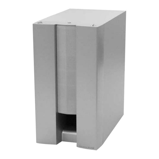
Active Subwoofer (SA-WMS325)
Center Speaker (SS-CN325)
Front and Rear Speakers (SS-V325)
SS-V325 (front and rear speakers)
Speaker system
Full range,
magnetically shielded
5.5 × 11 cm (
Speaker units
in.), cone type
Enclosure type
Bass reflex
Rated impedance
8 ohms
Power handling capacity
Maximum input power:
100 watts
Sensitivity level
87 dB (1 W, 1 m)
Frequency range
90 Hz - 20,000 Hz
Approx. 70 × 152 × 126
Dimensions (w/h/d)
7
mm (2
/
8
including front grille
Mass
Approx. 830 g (18 lb 5
oz) each
SS-CN325 (center speaker)
Full range × 2,
Speaker system
magnetically shielded
5.5 × 11 cm (
Speaker units
in.), cone type
Enclosure type
Bass reflex
Rated impedance
8 ohms
Power handling capacity
Maximum input power:
120 watts
Sensitivity level
89 dB (1 W, 1 m)
Frequency range
90 Hz - 20,000 Hz
Dimensions (w/h/d)
Approx. 300 78
126 mm (11
5 in.), including front
grille
Mass
Approx. 1600 g (35 lb 4
oz)
Sony Corporation
9-929-572-12
2001G0500-1
Home Audio Company
C 2001.7
Shinagawa Tec Service Manual Production Group
SA-VE322/VE325/WMS325/
SA-WMS325
SS-V325
SA-VE322
SA-VE325
a
–
a
SPECIFICATIONS
SA-WMS325 (subwoofer)
Speaker system
×
7
7
Speaker unit
/
/
32
16
Enclosure type
Reproduction frequency range
Amplifier section
Continuous RMS power output
× 6 × 5 in.),
Inputs
LINE IN (input pin jack)
SPEAKER IN (input terminals)
Outputs
LINE OUT (output pin jack)
SPEAKER OUT (output terminals)
×
7
/
7
/
32
16
General
Power requirements
North American model:
European model:
Other models:
Power consumptions
× 3
×
/
/
7
1
8
8
Dimensions (w/h/d)
Mass
SS-CN325/V325
SS-CN325
a
a
a
Active subwoofer,
magnetically shielded
Woofer: 16 cm (6
/
in.),
3
8
cone type
Advanced SAW type
28 Hz - 200 Hz
75 W (8 ohms, 20 Hz -
20 kHz, 0.8% THD)
120 V AC, 60 Hz
220 - 230 V AC, 50/60 Hz
110 - 120 V/220-240 V
AC, 50/60 Hz
70 W
1 W (standby mode)
Approx. 205 × 385 × 389
× 15
× 15
mm (8
1
/
1
/
3
/
8
4
4
in.), including front grille
Approx. 10.3 kg
(22 lb 11 oz)
MICRO SATELLITE SYSTEM
US Model
Canadian Model
E Model
Australian Model
Chinese Model
SA-VE325
AEP Model
UK Model
SA-VE322/VE325
Supplied accessories
SA-VE325
Foot pads (20)
Audio connecting cord (1)
Speaker connecting cords, 10 m (32 ft 9
Speaker connecting cords, 3.5 m (11 ft 6 in.) (3)
1
Speaker connecting cords, 2.5 m (8 ft 2
SA-VE322
Foot pads (8)
Audio connecting cord (1)
Speaker connecting cords, 3.5 m (11 ft 6 in.) (2)
Speaker connecting cords, 2.5 m (8 ft 2
1
Design and specifications are subject to change without
notice.
3
/
in.) (2)
4
/
in.) (2)
2
/
in.) (2)
2
Advertisement
Table of Contents

Related Manuals for Sony SA-VE322


Summary of Contents for Sony SA-VE322
- Page 1 Australian Model Chinese Model SA-VE325 AEP Model UK Model SA-VE322/VE325 SA-WMS325 SS-V325 SS-CN325 • SA-VE322/VE325 consists of the following models respectively. SA-VE322 SA-VE325 Active Subwoofer (SA-WMS325) Center Speaker (SS-CN325) – Front and Rear Speakers (SS-V325) SPECIFICATIONS SS-V325 (front and rear speakers)
-
Page 2: Safety Check-Out
OPERATION. REPLACE THESE COMPONENTS WITH DE FONCTIONNEMENT. NE REMPLACER CES COM- SONY PARTS WHOSE PART NUMBERS APPEAR AS POSANTS QUE PAR DES PIÈCES SONY DONT LES SHOWN IN THIS MANUAL OR IN SUPPLEMENTS PUB- NUMÉROS SONT DONNÉS DANS CE MANUEL OU LISHED BY SONY. -
Page 3: Section 1 Diagrams
SA-VE322/VE325/WMS325/SS-CN325/V325 SECTION 1 DIAGRAMS 1-1. NOTE FOR PRINTED WIRING BOARDS AND SCHEMATIC DIAGRAMS Note on Printed Wiring Board: Note on Schematic Diagram: • All capacitors are in µF unless otherwise noted. pF: µµF • : Pattern from the side which enables seeing. -
Page 4: Printed Wiring Board - Main Section (Sa-Wms325)
SA-VE322/VE325/WMS325/SS-CN325/V325 1-2. PRINTED WIRING BOARD – MAIN Section (SA-WMS325) – • See page 3 for Circuit Boards Location. MAIN BOARD CONNECTOR BOARD CN202 (Page 7) IC102 IC103 J101 LINE TM101 SPEAKER IC101 – – POWER BOARD CN401 • Semiconductor –... - Page 5 SA-VE322/VE325/WMS325/SS-CN325/V325 1-3. SCHEMATIC DIAGRAM – MAIN Section (SA-WMS325) – (Page 6) (Page 9) (Page 9) (Page 9) (Page 6) The components identified by mark 0 or dotted Les composants identifiés par une marque 0 sont line with mark 0 are critical for safety.
- Page 6 SA-VE322/VE325/WMS325/SS-CN325/V325 1-4. SCHEMATIC DIAGRAM – CONTROL Section (SA-WMS325) – (Page 5) (Page 5) The components identified by mark 0 or dotted Les composants identifiés par une marque 0 sont line with mark 0 are critical for safety. critiques pour la sécurité. Ne les remplacer que Replace only with part number specified.
-
Page 7: Printed Wiring Boards - Control Section (Sa-Wms325)
SA-VE322/VE325/WMS325/SS-CN325/V325 1-5. PRINTED WIRING BOARDS – CONTROL Section (SA-WMS325) – • See page 3 for Circuit Boards Location. CONNECTOR BOARD CONTROL BOARD MAIN BOARD CN101 (Page 4) (11) IC201 1-680-781- MODE BOARD (11) S901 LEVEL MODE MOVIE MUSIC (11) POWER BOARD... -
Page 8: Printed Wiring Boards - Power Section (Sa-Wms325)
SA-VE322/VE325/WMS325/SS-CN325/V325 1-6. PRINTED WIRING BOARDS – POWER Section (SA-WMS325) – • See page 3 for Circuit Boards Location. AUTO POWER BOARD (SP) MAIN BOARD CN502 (Page 4) T601 POWER TRANSFORMER (EXCEPT SP) RY601 S601 (SP) VOLTAGE (EXCEPT SP) SELECTOR 220-240V... - Page 9 SA-VE322/VE325/WMS325/SS-CN325/V325 1-7. SCHEMATIC DIAGRAM – POWER Section (SA-WMS325) – (Page 5) (Page 5) (Page 5) The components identified by mark 0 or dotted Les composants identifiés par une marque 0 sont line with mark 0 are critical for safety. critiques pour la sécurité. Ne les remplacer que Replace only with part number specified.
-
Page 10: Section 2 Exploded Views
SA-VE322/VE325/WMS325/SS-CN325/V325 SECTION 2 EXPLODED VIEWS NOTE: 2-2. SS-CN325 The components identified by • -XX and -X mean standardized parts, so they • Items marked “*” are not stocked since they mark 0 or dotted line with mark may have some difference from the original are seldom required for routine service. - Page 11 SA-VE322/VE325/WMS325/SS-CN325/V325 2-3. SA-WMS325 not supplied supplied with RV201 not supplied supplied with S901 not supplied not supplied T601 not supplied T501 The components identified by mark 0 or dotted line with mark 0 are critical for safety. Replace only with part number specified.
-
Page 12: Section 3 Electrical Parts List
SA-VE322/VE325/WMS325/SS-CN325/V325 SECTION 3 ELECTRICAL PARTS LIST AUTO POWER CONNECTOR CONTROL NOTE: • Due to standardization, replacements in the • Items marked “*” are not stocked since they The components identified by mark 0 or dotted line with mark parts list may be different from the parts speci- are seldom required for routine service. - Page 13 SA-VE322/VE325/WMS325/SS-CN325/V325 CONTROL MAIN Ref. No. Part No. Description Remark Ref. No. Part No. Description Remark C206 1-164-159-11 CERAMIC 0.1uF C503 1-117-782-11 ELECT 6800uF C207 1-164-159-11 CERAMIC 0.1uF C504 1-117-782-11 ELECT 6800uF < IC > C505 1-104-665-11 ELECT 100uF C506 1-104-665-11 ELECT...
- Page 14 SA-VE322/VE325/WMS325/SS-CN325/V325 MAIN Ref. No. Part No. Description Remark Ref. No. Part No. Description Remark Q302 8-729-035-30 TRANSISTOR 2SA1174TP-PFE R301 1-249-427-11 CARBON 6.8K 1/4W Q303 8-729-035-30 TRANSISTOR 2SA1174TP-PFE R302 1-249-441-11 CARBON 100K 1/4W Q304 8-729-119-78 TRANSISTOR 2SC2785TP-HFE R303 1-249-403-11 CARBON 1/4W...
- Page 15 SA-VE322/VE325/WMS325/SS-CN325/V325 MODE POWER POWER SWITCH Ref. No. Part No. Description Remark Ref. No. Part No. Description Remark 1-680-782-11 MODE BOARD 0 115 1-783-820-11 CORD, POWER (US, CND, MX) 0 115 1-783-941-22 CORD, POWER (AR) ************ 1-529-593-21 SPEAKER (16cm) < SWITCH >...
-
Page 16: Revision History
SA-VE322/VE325/WMS325/SS-CN325/V325 REVISION HISTORY Clicking the version allows you to jump to the revised page. Also, clicking the version at the upper right on the revised page allows you to jump to the next revised page. Ver. Date Description of Revision 2001.07...