Sony TCM-23DV Operating Instructions (primary manual) Service Manual
Cassette-corder
Hide thumbs
Also See for TCM-23DV Operating Instructions (primary manual):
- Operating instructions manual (10 pages) ,
- Service manual (16 pages) ,
- Service manual (16 pages)
Advertisement
SERVICE MANUAL
Ver 1.0 2000. 02
Recording system
Tape speed
Frequency range
Speaker
Power output
Input
Output
Variable range of the tape speed
Power requirements
Dimensions (w/h/d) (incl. projecting
parts and controls)
Mass
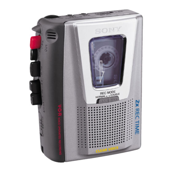
Photo: TCM-20DV
Model Name Using Similar Mechanism
Tape Transport Mechanism Type
SPECIFICATIONS
Supplied accessories
a
a
a
a
a
a
a
a
a
a
a
a
Battery life
Playback
Recording
Note
TCM-20DV/21DV/
22DV/23DV
US Model
TCM-20DV/21DV/22DV/23DV
Canadian Model
AEP Model
Chinese Model
House Current
(see Fig. A- )
Polarity of
the plug
Note
CASSETTE-CORDER
TCM-20DV/22DV
TCM-20DV/21DV
E Model
TCM-20DV/23DV
TCM-20DV
NEW
MT-20DV-118
Advertisement
Table of Contents

Related Manuals for Sony TCM-23DV Operating Instructions (primary manual)


Summary of Contents for Sony TCM-23DV Operating Instructions (primary manual)
- Page 1 SERVICE MANUAL Ver 1.0 2000. 02 Recording system Tape speed Frequency range Speaker Power output Input Output Variable range of the tape speed Power requirements Dimensions (w/h/d) (incl. projecting parts and controls) Mass TCM-20DV/21DV/ Photo: TCM-20DV Model Name Using Similar Mechanism Tape Transport Mechanism Type SPECIFICATIONS Supplied accessories...
-
Page 2: Table Of Contents
SUR LES DIAGRAMMES SCHÉMATIQUES ET LA LISTE DES PIÈCES SONT CRITIQUES POUR LA SÉCURITÉ DE FONCTIONNEMENT. NE REMPLACER CES COM- POSANTS QUE PAR DES PIÈCES SONY DONT LES NUMÉROS SONT DONNÉS DANS CE MANUEL OU DANS LES SUPPLÉMENTS PUBLIÉS PAR SONY. -
Page 3: General
• Location of Controls Built-in mic BATT z REC x STOP B PLAY m REW/ REVIEW SPEED CONTROL PAUSE M FF/CUE SECTION 2 GENERAL DC IN 3 V – 3 – This section is extracted from instruction manual. REC TIME... -
Page 4: Disassembly
SECTION 3 DISASSEMBLY • This set can be disassembled in the order shown below. MAIN BOARD, MECHANISM DECK (MT-20DV-118) BELT CABINET (REAR), CASSETTE LID Note: Follow the disassembly procedure in the numerical order given. CABINET (REAR), CASSETTE LID INSTALLATION CASSETTE SPRING cabinet front 9 cassette lid cassette lid... - Page 5 MAIN BOARD, MECHANISM DECK (MT-20DV-118) 5 three screws (IB lock) 1 Remove the two solders electret condenser microphone (MIC101). 4 MAIN board 1 Remove the two solders magnetic head (HRP901). BELT 1 belt (capstan) 3 screw (M1.4) 2 belt (FR) –...
- Page 6 INSTALLATION MAIN BOARD On installation MAIN board, adjust to the S101 and the S102. S102 (POWER) screw (1.7) – 6 – screw (M1.4) MAIN board S101 (REC/PB) lever (REC)
-
Page 7: Mechanical Adjustments
SECTION 4 MECHANICAL ADJUSTMENTS 1. Clean the following parts with a denatured-alcohol-moistened swab: record/playback head pinch roller erase head rubber belt capstan idlers 2. Demagnetize the record/playback head with a head demagne- tizer. (Do not bring the head demagnetizer close to the erase head.) 3. -
Page 8: Electrical Adjustments
Setting: • Supplied voltage: 2.5 V • Switch and control position [VOL control (RV101) : mechanical center [PAUSE switch (S105) : OFF [SPEED CONTROL] (RV602): center click [VOR] switch (S104) : OFF Test Tape Type Signal P-4-A063 6.3 kHz, –10 dB Head Azimuth Adjustment WS-48A 3 kHz, 0 dB... -
Page 9: Diagrams
SECTION 6 DIAGRAMS 6-1. BLOCK DIAGRAM MIC101 J101 (PLUG IN POWER) Q101 CONTROL MIC AMP, REC/PB EQ AMP IC101 (1/3) MIC IN S101 (REC/PB) S101 (4/6) EQ IN HRP901 (REC/PB) VREF HE901 S101 (1/6) (ERASE) CONT REC OUT POWER ON S601-2 REC TIME DOUBLE... -
Page 10: Printed Wiring Board
TCM-20DV/21DV/22DV/23DV 6-2. PRINTED WIRING BOARDS MAIN BOARD (COMPONENT SIDE) C137 R127 Q112 Q108 Q109 R604 B C E S105 Q107 PAUSE B C E B C E Q110 C138 R136 RV602 SPEED CONTROL • Semiconductor Location Ref. No. Location Ref. No. Location D101 A-13 Q105... -
Page 11: Schematic Diagram
6-3. SCHEMATIC DIAGRAM • See page 15 for IC Block Diagram. – 13 – TCM-20DV/21DV/22DV/23DV Note on Schematic Diagram: • All capacitors are in µF unless otherwise noted. pF: µµF • Voltages are dc with respect to ground under no-signal 50 WV or less are not indicated except for electrolytics conditions. -
Page 12: Exploded Views
• IC Block Diagram IC101 LA4168ML-TE-L PAUSE 2.2k Vref – SPEED 300k – 15 – NOTE: • -XX and -X mean standardized parts, so they may have some difference from the original one. • Color Indication of Appearance Parts Example: KNOB, BALANCE (WHITE) . - Page 13 (2) MECHANISM DECK SECTION-1 (MT-20DV-118) HRP901 HE901 supplied Ref. No. Part No. Description X-3377-250-1 LEVER, (2) ASSY, PINCH 3-925-146-01 BUTTON (FF) (M) 3-925-147-01 BUTTON (REW) (m) 3-925-148-01 BUTTON (PLAY) (N) 3-925-145-01 BUTTON (REC) (z) 3-924-738-01 BUTTON (STOP) (x) 3-703-925-21 SCREW (M1.4) 3-924-625-01 LEVER (HEAD) 3-924-645-01 BRACKET (HEAD) 3-924-685-01 SPRING (AZIMUTH), COMPRESSION...
- Page 14 (3) MECHANISM DECK SECTION-2 (MT-20DV-118) Ref. No. Part No. Description 3-321-483-11 RING, RETAINING (0.25) 3-315-495-31 WASHER X-3370-384-1 FLYWHEEL ASSY 3-924-623-01 LEVER (PLAY) 3-924-621-01 LEVER (REW) 3-924-620-01 LEVER (FF) X-3370-388-1 TABLE ASSY, FELT 3-924-642-01 SPRING (FR), TORSION 3-924-629-01 LEVER (DETECTION) 3-925-207-01 SPRING (S. OFF), TENSION 3-924-630-01 LEVER (S.OFF) X-3370-387-1 LEVER ASSY, IDLER 3-924-682-01 BELT (FR)
-
Page 15: Electrical Parts List
NOTE: • Due to standardization, replacements in the parts list may be different from the parts speci- fied in the diagrams or the components used on the set. • -XX and -X mean standardized parts, so they may have some difference from the original one. - Page 16 8-814-296-90 MICROPHONE, CONDENSER ECM-TC60 The components identified by mark 0 or dotted line with mark 0 are critical for safety. Replace only with part num- ber specified. Sony Corporation Personal Audio Division Company – 20 – Description Remark < THERMISTOR >...