Table of Contents
Advertisement
Advertisement
Table of Contents

Related Manuals for Midland DBR2500


Summary of Contents for Midland DBR2500
-
Page 2: Table Of Contents
TABLE OF CONTENTS WELCOME TO THE WORLD OF MIDLAND RADIO � � � � � � � � � � � � � � � � � FEATURES � � � � � � � � � � � � � � � � � � � � � � � � � � � � � � � � � � � � � � � � � � � � � � � � �... - Page 3 Model DBR2500 FUNCTION MENU (Continued) Squelch Level Setup � � � � � � � � � � � � � � � � � � � � � � � � � � � � � � � � � � � � � � � � � � � � � � � � � � � � 21 Volume Level Setting �...
-
Page 4: Welcome To The World Of Midland Radio
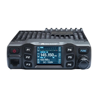
Congratulations on your purchase of a high quality product�Your DBR2500 Dual Band Amatuer radio represents state-of-the-art engineering� The circuitry is all solid-state and mounted on a rugged printed circuit board� Your DBR2500 radio is designed for reliable and trouble-free performance�... -
Page 5: Exposure To Radio Frequency Energy / Licensing
FCC’s website: http://www�fcc�gov and request form 605� Exposure To Radio Frequency Energy Your Midland radio is designed to comply with the following national and international standards and guidelines regarding exposure of human beings to radio frequency electromagnetic energy�... -
Page 6: Installing Your Radio
Car body Washer (M5) Tapping screw (M5x20mm) Mounting bracket 2� Position the tranceiver, then insert and tighten the supplied hexagon screws� -Double check that all screws are tightened to prevent vehicle vibration from loosening the bracket or DBR2500� midlandusa.com page 6... -
Page 7: Dc Power Cable Connection
Model DBR2500 DC POWER CABLE CONNECTION Locate the power input connector as close to the DBR2500 as possible. Mobile Operation The vehicle battery must have a nominal rating of 12V� Never connect the tranceiver to a 24V battery. Be sure to use a 12V battery that has sufficient current capacity. If the current to the tranceiver is insufficient, the display may darken during transmission, or transmitting power may be dramatically reduced�... -
Page 8: Fixed Station Operation
Model DBR2500 Fixed Station Operation In order to use this DBR2500 for fixed station operation, you will need a separate 13.8V DC power supply (not included)� The recommended current capacity of your power supply is 12A 1�Connect the DC power cable to the regulated DC power supply and ensure that the polarities are correct�... -
Page 9: Installing The Antenna
Use a 50Ω impedance antenna and low-loss coaxial feed-line that has a characteristic impedance of 50Ω, to match the DBR2500 input impedance� Coupling the antenna to the DBR2500 via feed-lines having an impedance other than 50Ω... -
Page 10: Accessory Connections
Model DBR2500 6� When routing the antenna cable inside the vehicle, keep the cable away from noise sources, such as the ignition system, gauges, etc� 7� Exercise care to prevent cable damage� Make use of existing gaskets, grommets and weather stripping to protect the cable along its route�... -
Page 11: Microphone
Model DBR2500 Microphone Insert the 8P8C (commonly “RJ45”) connector into the front of the DBR2500. Press firmly on the plug until the locking tab clicks� CONTROLS AND INDICATORS Front Panel midlandusa.com page 11... -
Page 12: Rear Panel
Model DBR2500 Button Functions User programmable button (also referred to as a “[P:X] button”) Power On / Off / Mute User programmable button (also referred to as a “[P:X] button”) Microphone Jack User programmable button (also referred to as a “[P:X] button”) -
Page 13: Display
Model DBR2500 Display Functions Displays the user programmable function if you press P1 Displays the user programmable function if you press P2 Displays the user programmable function if you press P3 Displays the user programmable function if you press P4... -
Page 14: Microphone
Model DBR2500 Displays when sub-channel reverse function is on Displays when sub-channel offset function is on Displays when sub-channel is receiving a signal Displays signal strength Displays when main channel is in scan list Microphone Button Functions Increase frequency, channel number, or setting value... -
Page 15: Operating Your Radio
Using the programming software: Access the software’s “General Setting” menu, choose the “Display Mode” to select VFO mode or Channel mode� b� To set Working Mode on the DBR2500: Please refer to “Display Mode” on Page 21� 2. VFO Transceiver Mode If the DBR2500 does not display “CH”... -
Page 16: Basic Operations
Model DBR2500 BASIC OPERATIONS Switching the power On/Off Press and release the button to power on the radio, or program the radio to automatically power on using the function menu. Hold the button for over 2 seconds to power off the radio�... -
Page 17: Receiving
2�5 - 5�0cm from your mouth� Switch between Main Channel and Sub-Channel The DBR2500 features dual channel monitor, in standby, the frequency on the top is the main channel and the frequency on the lower portion is the sub-channel� The radio can only transmit on the main channel�... -
Page 18: Channel Delete
Model DBR2500 3� Press and hold the [FUNC] button to enter channel setting menu, to choose the desired setting� 4� Press and release the [FUNC] button to switch the function group, hold the [P:X] button defined as V/M function until the channel number flashes, if the channel number is red it means the current channel is valid, if the channel number is green, it means that the current channel is empty�... -
Page 19: Ctcss Scan
Model DBR2500 CTCSS Scan In channel or VFO mode, press and release [FUNC] to switch function group, choose the [P:X] button defined as CDT function. press and release this button to enter CTCSS code setting. When the LCD displays CTC, press and hold this button to enter CTCSS scan� Turn channel knob or press microphone [UP]/[DOWN] button to change scan direction. -
Page 20: Squelch Off/Squelch Off Momentarily
Model DBR2500 Squelch off/Squelch off Momentarily The [P:X] button defined as MON function, can monitor for weak signals 1. Press the [FUNC] button to switch function group, choose the [P:X] button defined as MON function 2. Press and release the [P:X] button defined as MON function to turn squelch off / squelch off momentary, the LCD displays red “RX”... -
Page 21: Beep
Model DBR2500 Beep 1� Enter the FUNCTION MENU list, choose the No�01 function 2� Press the [PUSH] button, the menu value in the LCD turns to green color 3. Turn the channel knob to choose desired setting. Off~5: 6 levels available. Off: Turn off the BEEP function 4�... -
Page 22: Setting A Password
Model DBR2500 Setting a Password If this function is enabled, the correct password must be input in order to turn on the DBR2500� Access the programming software (page 30) to set or change the password� The DBR2500 comes default from the factory with the password set to 123456�... -
Page 23: Dual Watch Setup
Model DBR2500 Dual Watch Setup 1� Enter FUNCTION MENU list, choose the No�10 function 2� Press the [PUSH] button, the menu value in the LCD turns to green 3� Turn channel knob to choose the desired setting ON: Enable Dual Watch function OFF: Disable Dual Watch function 4�... -
Page 24: Dir (Lcd Display Direction) Setup
4� Press the [PUSH] button or the [P3] button to store the setting and exit RTDF (RX/TX Dissimilar Frequency) Setup The DBR2500 has dissimilar frequency function, when this function is on, the frequency on the top portion of the LCD is the RX frequency, and the frequency on the bottom is the TX frequency�... -
Page 25: Channel Menu
Model DBR2500 1� Enter the FUNCTION MENU list, choose the No�18 function 2� Press the [PUSH] button, the menu value in the LCD turns to green 3� Turn the channel knob to choose the desired setting ALL: All channel, signaling function setup resume factory default OPT: All function menu setup resume factory default except CHAN MENU 4�... -
Page 26: High/Mid/Low Power Selection
Model DBR2500 4� When selecting CTCSS/DCS encode, press the [PUSH] button to enter CTCSS/DCS encode setup, then turn the channel knob to choose the desired CTCSS/DCS encode� CTCSS: 62.5-254.1HZ, and one self- define group, 52 total CTCSS groups DCS: 000N-777I, there are a total of 1024 DCS groups N is normal code, I is inverse code 5�... -
Page 27: Signaling Combination Setup
Model DBR2500 Signaling Combination Setup This function can improve the level of blocking of irrelevant signals 1� Enter the CHAN MENU, choose the No�6 function 2� Press the [PUSH] button, the menu value in the LCD turns to green 3� Turn the channel knob to choose the desired setting... -
Page 28: Offset Frequency And Direction Setup
Model DBR2500 3� Turn the channel knob to choose the desired setting ON: Turn on talk around function OFF: Turn off talk around function 4� Press the PUSH button or the [P3] button to store the setting and exit This function will be hidden when RTDF function is enabled. -
Page 29: Transmit (Tx) Off
Model DBR2500 Transmit (TX) Off 1� Enter the CHAN MENU list, choose the No�13 function 2� Press the [PUSH] button, the menu value in the LCD turns to green 3� Turn the channel knob to choose the desired setting ON: TX allowed, press the [PTT] to transmit OFF: TX not allowed, only work in RX mode, press the [PTT] to emit a beep 4�... -
Page 30: H-Pa / H-Pd Micrphone Self-Define Keypad Setup
USB cable to the DBR500� 1� Once the software is installed, open the “DBR2500” program folder from the start menu on the computer, select and open “USB To Com Port” in the DBR2500 program folder, install the “USB To Com Port”... -
Page 31: Maintenance
Make sure the DBR2500 is powered on prior to writing any data to the radio� Do not turn off the DBR2500 while it is connected to the computer. Doing so will cause the DBR2500 to disconnect from the computer, thus not allowing the computer to read/write to the DBR2500�... -
Page 32: Troubleshooting
Model DBR2500 TROUBLESHOOTING Problem Possible Causes and Potential Solutions + and - polarities of power connection are reversed� Connect (1) Power is on, nothing red lead to plus terminal and black lead to minus terminal of appears on Display DC power supply... -
Page 33: Specifications
Model DBR2500 SPECIFICATIONS midlandusa.com page 33... -
Page 34: Ctcss Tone Frequency Chart (Hz)
Model DBR2500 CTCSS TONE FREQUENCY CHART (HZ) Freq. Freq. Freq. Freq. Freq. (Hz) (Hz) (Hz) (Hz) (Hz) 62�5 94�8 136�5 177�3 218�1 97�4 141�3 179�9 225�7 69�3 100�0 146�2 183�5 229�1 71�9 103�5 151�4 196�2 233�6 74�4 107�2 156�7 189�9 241�8... -
Page 35: Dcs Codes Frequency Chart
Model DBR2500 DCS CODES FREQUENCY CHART Code Code Code Code Code Code Code Code (Octal) (Octal) (Octal) (Octal) (Octal) (Octal) (Octal) (Octal) 100. 101. 102. 103. 104. 105. 106. 107. 108. 109. 110. 111. 112. 113. 114. 115. 116. 117. - Page 36 Model DBR2500 313. 314. 315. 316. 317. 318. 319. 320. 321. 322. 323. 324. 325. 326. 327. 328. 329. 330. 331. 332. 333. 334. 335. 336. 337. 338. 339. 340. 341. 342. 343. 344. 345. 346. 347. 348. 349. 350.
-
Page 37: Fcc Warnings And Statements
IMPORTANT! MIDLAND RADIO CORPORATION makes no warranty or claim regarding any modification to your DBR2500 not fully authorized by MIDLAND RADIO CORPORATION, nor any change in operability, performance, or regulatory compliance arising therefrom� You are solely responsible for operating your DBR2500 in accordance with the law�... -
Page 38: Limited Warranty (United States And Canada)
Subject to the exclusions set forth below, Midland Radio Corporation will repair or replace, at its option without charge, any Midland UHF transceiver which fails due to a defect in material or workmanship within One Year following the initial consumer purchase�... - Page 39 Model DBR2500 midlandusa.com page 39...
- Page 40 We’d love to hear from you! Let us know what you think of your new Midland product at or by visiting us at midlandusa�com Note: Features & Specifications are subject to change without notice� MIDLAND is not responsible for unintentional errors or omissions on its packaging� midlandusa.com page 40...