
Related Manuals for Danfoss DGS Series


Summary of Contents for Danfoss DGS Series
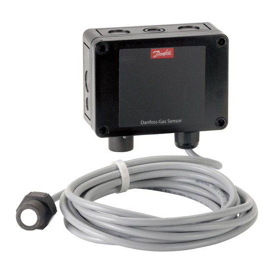
- Page 1 User Guide Danfoss Gas Sensor Type DGS Modbus or Service Tool display operation danfoss.com...
-
Page 2: Table Of Contents
User Guide | Danfoss Gas sensor. Type DGS. Modbus or Service Tool display operation Contents Page 1. Intended use ..................4 2. - Page 3 User Guide | Danfoss Gas sensor. Type DGS. Modbus or Service Tool display operation © Danfoss | DCS (ADAP-KOOL®) | 2018.12 RS8KD102 | 3...
-
Page 4: Intended Use
User Guide | Danfoss Gas sensor. Type DGS. Modbus or Service Tool display operation The display of the handheld Service Tool and the Intended use Modbus interface for integration with Building Management Systems is used as interface for operation, commissioning and calibration of the... - Page 5 User Guide | Danfoss Gas sensor. Type DGS. Modbus or Service Tool display operation Operation with the handheld Service Tool is described in sections 3.1 and 3.2 and chapter 4. Operation with the Danfoss Front End is described in chapter 5.
-
Page 6: Function Of The Keys And Leds On The Keypad
User Guide | Danfoss Gas sensor. Type DGS. Modbus or Service Tool display operation Exits programming, returns to the previous menu level. Function of the keys and LEDs on the keypad Enters sub menus, and saves parameter settings. Scrolls up & down within a menu, changes a value. -
Page 7: Code Levels
User Guide | Danfoss Gas sensor. Type DGS. Modbus or Service Tool display operation All inputs and changes are protected by a Code Levels four-digit numeric code (= password) against unauthorised intervention according to the regulations of all national and international standards for gas warning systems. - Page 8 User Guide | Danfoss Gas sensor. Type DGS. Modbus or Service Tool display operation Starting menu Menu Overview Main menu Chapter # (Continued) Error Status Reading and acknowledgement of errors See chapter 4.1 Alarm Status Display of the status of active alarms See chapter 4.2...
- Page 9 User Guide | Danfoss Gas sensor. Type DGS. Modbus or Service Tool display operation Starting menu Menu Overview Main menu Chapter # (Continued) Service The following menu items are only accessible with Service ON (password protected) !! Service ON = Special mode = Fault message is...
-
Page 10: Error Status
User Guide | Danfoss Gas sensor. Type DGS. Modbus or Service Tool display operation A pending fault activates the yellow LED (Fault). A number of error messages may be displayed Error status The integrated fault management records the related to the sensor; Out of Range, Wrong type,... -
Page 11: Menu Measuring Values
User Guide | Danfoss Gas sensor. Type DGS. Modbus or Service Tool display operation In this menu, the display shows the measuring Menu Measuring Values value with gas type and unit. Measuring Values D 1 CO2 Selection of the next measuring point... -
Page 12: Language
User Guide | Danfoss Gas sensor. Type DGS. Modbus or Service Tool display operation 4.5.2 Language Language English Selection of the menu language (password protected) Symbol Description Default Function English USA English English Language English German French Spanish 4.5.3 Function for testing the LCD function (password protected) LCD Function Check All LEDs light up for about two seconds. -
Page 13: Menu System Parameters
User Guide | Danfoss Gas sensor. Type DGS. Modbus or Service Tool display operation System Parameters Menu System Parameters 4.7.1 The configuration of the analog outputs. AO Function AO Function The analog output checks the current signal for validity. Signal deviations of more than 5% from... -
Page 14: Operating Data
User Guide | Danfoss Gas sensor. Type DGS. Modbus or Service Tool display operation This menu is for retrieving relevant operational data of the sensor head. Operating Data No changes or modifications are possible. Operating Data Operating Data If more than one sensor head is connected to the DGS, the selection is done at X. -
Page 15: Calibration
User Guide | Danfoss Gas sensor. Type DGS. Modbus or Service Tool display operation This section gives an overview of the calibration menu. Calibration The calibration description can be found on the following pages. For HFC, remember to use the specified calibration gas. -
Page 16: Zero Calibration
User Guide | Danfoss Gas sensor. Type DGS. Modbus or Service Tool display operation 4.9.1 The stepwise calibration process is described below. Zero Calibration Note: The specified warm-up times etc. must be strictly observed before starting the calibration process. Zero... -
Page 17: Gain Calibration
User Guide | Danfoss Gas sensor. Type DGS. Modbus or Service Tool display operation 4.9.2 The stepwise calibration process is described below. Gain Calibration Note: The specified warm-up times etc. must be strictly observed before starting the calibration process. Enter concentration of the test gas used. -
Page 18: Zero-Point Calibration Of Analog Output
User Guide | Danfoss Gas sensor. Type DGS. Modbus or Service Tool display operation 4.9.3 With this menu item you can adjust the zero-point of the analog output (4mA). The zero-point Zero-point Calibration of Analog correction is only possible when the minimum output is 2V or 4mA, i.e. not possible when minimum output is 0V or 0mA”. -
Page 19: Modbus Menu Survey
User Guide | Danfoss Gas sensor. Type DGS. Modbus or Service Tool display operation Modbus menu survey Function Factory Unit AKM name Gas level Sensor 1 Actual gas level in % of range 100.0 Gas level % Sensor 1 Actual gas level in ppm... - Page 20 User Guide | Danfoss Gas sensor. Type DGS. Modbus or Service Tool display operation Read out the attached Gas sensor type. Sensor type 1: HFC gr.1 R1234ze, R454c, R1234yf R1234yf, R454a, R452A R454b, R513a 2: HFC gr.2 R407F, R416a, R417a...
- Page 21 User Guide | Danfoss Gas sensor. Type DGS. Modbus or Service Tool display operation 0: OK, sensor in place Sensor removed 1: Fault, Sensor out or removed, or wrong sensor placed in 0: OK, Sensor not due for calibration Calibrate sensor...
-
Page 22: Technician Use Only
User Guide | Danfoss Gas sensor. Type DGS. Modbus or Service Tool display operation This unit must be installed by a suitably qualified Failure to install and operate the unit in Technician use only! technician who will install this unit in accordance... -
Page 23: Ordering
User Guide | Danfoss Gas sensor. Type DGS. Modbus or Service Tool display operation Ordering Spares and accessories DGS Sensors Product Description Code no. Product Description Code no. DGS-SC HFC gr. 1* 080Z2803 Spare sensor HFC gr.1* Spare 080Z2815 DGS-SC HFC gr. 2* 080Z2804 Spare sensor HFC gr.2*... - Page 24 24 | RS8KD102 © Danfoss | DCS (ADAP-KOOL®) | 2018.12...