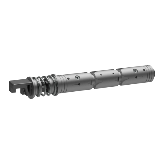
Danfoss PVG 32 Application Manual
Using flow or pressure control spools
Hide thumbs
Also See for PVG 32:
- Technical information (76 pages) ,
- Service manual (44 pages) ,
- Installation manual (10 pages)
Summary of Contents for Danfoss PVG 32
- Page 1 Application Guide PVG 32 Using flow or pressure control spools powersolutions.danfoss.com...
- Page 2 Application Guide Using flow or pressure control spools Revision history Table of revisions Date Changed Feb 2017 First edition 0101 © Danfoss | Feb 2017 AB00000079en-US0101...
-
Page 3: About This Document
Work Port Flow Important user information Danfoss is not responsible or liable for indirect or consequential damages resulting from the use or application of this equipment. The examples and diagrams in this manual are included for illustration purposes. Due to the many variables and requirements associated with any particular installation, Danfoss cannot assume responsibility or liability for the actual used bases on the examples and diagrams. -
Page 4: Application Overview
Using flow or pressure control spools Application overview Danfoss introduced the PVG 32 pressure control (PC) spools to the market in the 1990s to overcome instability problems on applications and to control the opening of counterbalance (CB) valves. Typically, a main boom on a crane could be applied with a CB valve for safety reasons. -
Page 5: Functionality Of A Flow Control Spool
FC spool on page 5. A certain position of the spool will always give the same amount of flow out of the valve independent of load changes on the work ports. FC spool © Danfoss | Feb 2017 AB00000079en-US0101 | 5... -
Page 6: Flow Control Spools In Oscillating Systems
So an FC spool offers no damping of the system but maintains a constant flow. © Danfoss | Feb 2017 AB00000079en-US0101... -
Page 7: Functionality Of A Pressure Control Spool
Pl. As a result, the spool deadband varies as the size of the load changes. So for PC spools a certain position of the main spool is proportional to a certain Pc pressure. © Danfoss | Feb 2017 AB00000079en-US0101 | 7... - Page 8 One of the drawbacks of a PC spool is that flow out of the valve is dependent on the size of the load and with variable deadband. PC control to B port on page 8 illustrates a cut through PVB with PC control to one port. PC control to B port © Danfoss | Feb 2017 AB00000079en-US0101...
-
Page 9: Pressure Control Spools In Oscillating Systems
The flow out, Ql, is also shown on the graph as a dotted line. The amount of dampening applied is dependent on the relative difference in pressure between spool set point pressure and load varying pressure. The relative difference is shown on the graph as ΔP1 and ΔP2. © Danfoss | Feb 2017 AB00000079en-US0101 | 9... -
Page 10: Pressure Control Spools With Counterbalance Valves
Typically, a spool with FC in one direction (lifting) and PC in the other direction (lowering) is used for applications with CB valves to provide the best controllability in both cases. 10 | © Danfoss | Feb 2017 AB00000079en-US0101... - Page 11 A situation in which PC spools are of great value is when you are lowering a load in an application that uses counterbalance (CB) valves. A combined FC and PC spool, with the FC in the lifting port and the PC in the lowering port, results in optimal controllability. © Danfoss | Feb 2017 AB00000079en-US0101 | 11...
- Page 12 Phone: +86 21 3418 5200 Danfoss can accept no responsibility for possible errors in catalogues, brochures and other printed material. Danfoss reserves the right to alter its products without notice. This also applies to products already on order provided that such alterations can be made without changes being necessary in specifications already agreed.


