Table of Contents
Advertisement
NOTE: Specifications are correct at time of printing and are subject to change without notice.
* Actual sustained engine power will likely be lower due to operating limitations and environmental factors. Please refer to 'Engine Power Rating Information' for
further details.
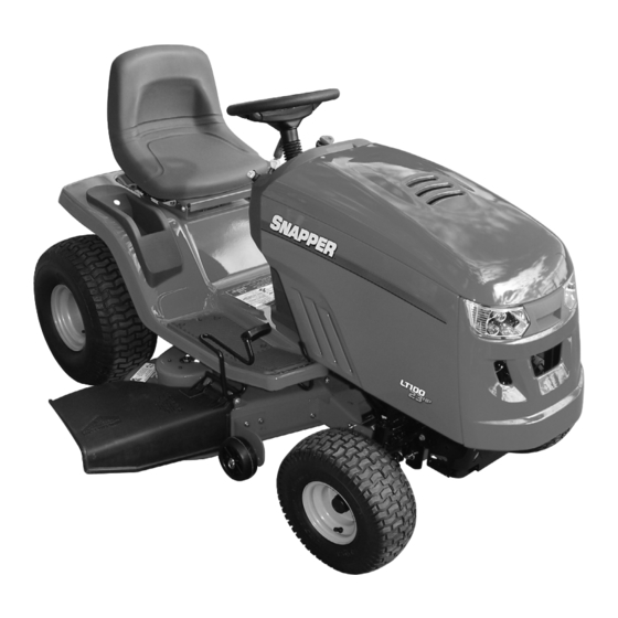
Safety Instructions & Operator's Manual for
LAWN TRACTOR
SERIES 0
Models
LT195420 (7800206)
CLT195420 (7800313)
LT23460 (7800207)
CLT23460 (7800315)
LT24520 (7800212)
CLT24520 (7800317)
SLT23460 (7800342)
SLT24520 (7800343)
CSLT23460 (7800344)
CSLT24520 (7800345)
SLT23460FC (7800316)
SLT24520FC (7800318)
Manual No. 7102556 (Rev. '-', 4/17/2008)
TP 100-5396---TC-N
Advertisement
Table of Contents

Related Manuals for Snapper LT195420, CLT195420, LT23460, CLT23460, LT24520, CLT24520, SLT23460, CSLT24520, SLT23460FC, SLT24520FC


Summary of Contents for Snapper LT195420, CLT195420, LT23460, CLT23460, LT24520, CLT24520, SLT23460, CSLT24520, SLT23460FC, SLT24520FC
- Page 1 NOTE: Specifications are correct at time of printing and are subject to change without notice. * Actual sustained engine power will likely be lower due to operating limitations and environmental factors. Please refer to ‘Engine Power Rating Information’ for further details. Safety Instructions &...
-
Page 2: Model Number
This manual contains safety information to make you aware of the hazards and risks associated with mowers and how to avoid them. Because Snapper does not necessarily know all the applications this mower could be used for, it is important that you read and understand these instructions. -
Page 3: Table Of Contents
Table of Contents Operator Safety ........Important Operator Safety Instructions ......International Pictorials . -
Page 4: Operator Safety
If you have any questions pertaining to your machine which your dealer cannot answer to your satisfaction, call or write the Customer Service Department at SNAPPER, McDonough, Georgia 30253. Phone: (1-800-317-7833). Protection for Children Tragic accidents can occur if the operator is not alert to the presence of children. - Page 5 13. Exercise CAUTION when pulling loads. Limit loads to those you can safely control and attach loads to hitch plate as specified with SNAPPER attachment instructions. 14. On slopes, the weight of the towed equipment may cause loss of traction and loss of control. When towing, travel slowly and allow extra distance to stop.
- Page 6 13. DO NOT test for spark by grounding spark plug next to spark plug hole; spark plug could ignite gas exiting engine. 14. Have machine serviced by an authorized SNAPPER dealer at least once a year and have the dealer install any new safety devices.
-
Page 7: International Pictorials
International Pictorials IMPORTANT: Some of the following pictorials are located on your unit or on literature supplied with the product. Before you operate the unit, learn and understand the purpose for each pictorial. Figure 1: Safety warning pictorials A - Warning B - Shield Eyes. -
Page 8: Assembly
WARNING: Before doing any assembly or maintenance to the mower, remove the wire from the spark plug. D - (1) Washer E - (2) Knob F - (2) Washer G - (1) Keys & ring H - (1) Terminal cover www.snapper.com... -
Page 9: Installing The Seat
Installing the Seat How to Install the Seat 1. Carefully remove the plastic bag from the seat. Use the fasteners shown below to install the seat. The fasteners are shown at full size. Figure 4: Seat parts A - Wing bolt (Also see ‘E’ in Figure 3) B - Washer (Also see ‘F’... -
Page 10: Maintenance Free Battery
Use the fasteners shown below to install the battery cables. The fasteners are shown at full size. Figure 8: Battery cable parts A - Carriage bolt (Also see ‘A’ in Figure 3) B - Wing nut (Also see ‘B’ in Figure 3) www.snapper.com... -
Page 11: Important! Before You Start Mowing
1. Remove the protective cap from the battery terminal. 2. Fasten the red cable and terminal cover (if equipped) to the positive (+) terminal with the fasteners as shown (Figure 9). 3. Fasten the black cable to the negative (-) terminal with the fasteners as shown. - Page 12 Make sure the level of cut is still correct. After you mow a short distance, look at the area that was cut. If the mower deck does not cut level, see the instructions on “How To Level The Mower Deck” in the Maintenance section of this instruction book. www.snapper.com...
-
Page 13: Features And Controls
Features and Controls A - Throttle Control / Choke Control Levers — Throttle control increases or decreases the speed of the engine. Choke control engages the choke to start a cold engine. (Note: The choke control lever is incorporated into the throttle control lever on 42”... -
Page 14: Operation
4. Before you ride the unit across a sidewalk or a road, move the blade rotation control to the DISENGAGE position. WARNING: Always keep your hands and feet away from the blade, deflector opening, and the mower housing when the engine runs. www.snapper.com... -
Page 15: Driving And Stopping The Unit
How to Engage the Blades (46 & 52” models) The PTO switch is above and to the right of the steering wheel (Figure 11). Use the PTO switch to engage the blades. Figure 11: PTO switch (46 & 52” models only) A - PTO switch (shown in the DISENGAGE position) 1. - Page 16 NOTE: In cold weather, the heavy viscosity oil in the transmission will make the unit difficult to push. 3. To engage the transmission, unlock and push in the automatic drive disconnect. The transmission is now connected and ready to operate. Fast Throttle www.snapper.com...
- Page 17 7101935 Figure 13: Automatic drive disconnect A - Automatic drive disconnect DRIVE position B - Automatic drive disconnect PUSH position C - Automatic drive disconnect How to Set the Parking Brake 1. Completely push the brake pedal forward. 2. Lift the parking brake lever (Figure 14). 3.
-
Page 18: Mowing
WARNING: The engine will shut off if the speed control pedal is moved into reverse while the blades are engaged and the RMO is not activated. Figure 16: Reverse Mowing Option (RMO) A - Key B - RMO switch C - L.E.D. light www.snapper.com... - Page 19 How to Operate the Unit on Hills WARNING: Do not ride up or down slopes that are too steep to back straight up. Never ride the unit across a slope. See the “Slope Guide” in the back of this book for information on how to check slopes. 1.
-
Page 20: Engine Operation
6. Turn off the choke, and slowly move the throttle control to the SLOW position. 7. Let a cold engine run for several minutes. Begin work when the engine is warm. To start a hot engine, move the throttle control to a position between FAST and SLOW. www.snapper.com... -
Page 21: Tips
Tips Operating Tips 1. Check the blade rotation control or the PTO clutch for correct adjustment. For the blades to disengage correctly, the adjustment must be correct. 2. Before you use the unit, check the oil in the engine and add oil if necessary. -
Page 22: Maintenance
Refer to the Engine Owner’s Manual. Refer to Maintenance section. Refer to Maintenance section. Refer to Where to Lubricate instructions. Refer to Maintenance section. Refer to the Engine Owner’s Manual. Refer to warnings in the Owner’s Manual. Refer to the Engine Owner’s Manual. www.snapper.com... -
Page 23: General Recommendations
General Recommendations 1. The owner’s responsibility is to maintain this product. This will extend the life of the product and is also necessary to maintain warranty coverage. 2. Check the spark plug, drive brake, lubricate the unit, and clean the air filter once a year. 3. -
Page 24: Adjustments
1. When you mow, make sure the throttle control in in the FAST position. 2. Move the blade rotation control to the DISENGAGE position (Figure 22). 3. Stop the engine. Disconnect the wire from the spark plug. www.snapper.com... - Page 25 Figure 22: Blade adjustments A - DISENGAGE Position B - Blade Rotation Control ENGAGE Position 4. Check the blade(s). Keep a sharp edge on the blade(s). A blade that is not sharp will cause the tips of the grass to become brown. 5.
- Page 26 PTO and check the amount of time it takes for the mower drive belt to stop. 3. If the mower drive belt does not stop within five seconds, perform the PTO Clutch Adjustment. If the belt still does not stop within 5 seconds, see your dealer. www.snapper.com...
- Page 27 How to Check and Adjust the Motion Drive Belt If the motion drive belt is loose, the belt will slip when; (1) going up a hill, (2) pulling a heavy load, or (3) the unit will not move forward. Adjust the belt as follows. WARNING: Before you make an inspection, adjustment, or repair to the unit, disconnect the wire to the spark plug.
-
Page 28: Maintenance Free Battery
(Figure 29). English Figure 29: Battery A - Carriage bolt B - Wing nut C - Black cable D - Positive (+) terminal E - Red cable F - Battery G - Battery tray H - Terminal cover www.snapper.com... -
Page 29: Lubrication
Lubrication Where to Lubricate Models with grease fittings: Lubricate with grease gun. Apply grease with a brush to the areas shown. Lubricate the areas shown with engine oil. NOTE: Apply grease to the steering gear assembly. CAUTION: If the unit is operated in dry areas that have sand, use a dry graphite spray to lubricate the unit. -
Page 30: Mower Deck Maintenance
8. Move the blade rotation control to the ENGAGE position. Make sure the mower drive belt is inside all the belt guides. 9. Make sure the mower deck is level. See the instructions on “How To Level The Mower Deck”. www.snapper.com... - Page 31 10. If equipped, install the gauge wheels. 11. Check the operation of the blade rotation control. See the instructions on “How To Adjust The Blade Rotation Control”. Figure 33: Mower deck assembly (42” models) A - View A B - View B C - View C D - View D E - View E...
- Page 32 See illustrations “C” and “D”. 7. Make sure the mower deck is level. See the instructions on “How To Level The Mower Deck”. 8. Check the operation of the PTO clutch. See the instructions on “How To Adjust The PTO Clutch”. www.snapper.com...
- Page 33 Figure 35: Mower deck assembly (46 & 52” models) (46” Deck Shown, 52” Deck Similar) A - View A B - View B C - View C D - View D E - View E F - View F G - Not Used H - Suspension link I - Adjuster arm J - Deck lift lever...
- Page 34 Make sure the tires are inflated to 14 PSI (1 BAR). IMPORTANT: On models equipped with gauge wheels, the gauge wheels must be removed to correctly adjust the level of the mower deck. 3,4,5,6 www.snapper.com...
- Page 35 3. Some models have gauge wheels on the mower deck. If equipped, remove the gauge wheels. 4. Move the deck lift lever to the LEVEL ADJUSTMENT position (Figure 39). WARNING: The deck lift lever is spring loaded. Make sure the lift lever is locked in the LEVEL ADJUSTMENT position.
- Page 36 9. Install the mower deck. See the instructions on “How To Install The Mower Deck”. 10. Before you mow, check the blade rotation control. See the instructions on “How To Adjust The Blade Rotation Control”. English www.snapper.com...
- Page 37 Figure 42: Mower drive belt assembly (42” models) A - Belt retainer B - Right mandrel pulley C - Idler pulley D - Mower drive belt E - Belt retainer F - Left mandrel pulley G - Belt retainer English...
- Page 38 12. Put the primary mower drive belt around the stack pulley. 13. Install the mower deck. See the instructions on “How To Install The Mower Deck”. 14. Before you mow, check the PTO clutch. See the instructions on “How To Adjust The PTO clutch”. www.snapper.com...
- Page 39 Figure 43: Mower drive belt assembly (46 & 52” models) (46” shown, 52” similar) A - Screw B - Left pulley cover C - Primary mower drive belt D - Left mandrel pulley E - Belt guides (Not used on some models) F - Stack pulley G - Idler pulleys H - Right pulley cover...
-
Page 40: Misc
If the fuse is blown, the engine will not start. The location of the fuse is behind the panel between the engine and the control console. Remove the fuse and replace with an automotive fuse of equivalent rating (Figure 46). Figure 46: Fuse location A - Automotive fuse www.snapper.com... -
Page 41: Storage
How to Replace the Light Bulb 1. Raise the tractor hood. 2. Turn the light socket until the tabs on the socket align with the notches in the bezel (Figure 46). Remove the light socket. Turn the light bulb and remove the bulb. 3. -
Page 42: Troubleshooting
3. Replace the fuel filter. 1. Replace the blade. 2. Check for loose engine bolts. Excessive vibration. 3. Decrease the air pressure in the tires. 4. Check for a damaged belt or damaged pulley. Replace the damaged parts. English Troubleshooting Chart www.snapper.com... - Page 43 Problem Correction 1. Stop the engine. Clean the mower deck. 2. Raise the height of cut. 3. Replace or sharpen the blade(s). The grass does not discharge correctly. 4 Use a slower ground speed. 5. Move the throttle control to the FAST position. 6.
-
Page 44: Specifications
1.5 - 4.0 1.5 - 4.0 Hydro Hydro 0 - 5.6 / 0 - 3.5 0 - 5.6 / 0 - 3.5 19.5 23.0 LT24520 CLT24520 SLT24520 CSLT24520 SLT24520FC 1.5 - 4.0 Hydro 0 - 5.6 / 0 - 3.5 24.0 www.snapper.com... -
Page 45: Slope Guide
English... - Page 46 Notes English www.snapper.com...
-
Page 47: Warranties
For two (2) years from purchase date for the original purchaser’s residential, non-commercial use, SNAPPER, through any authorized SNAPPER dealer will replace, free of charge (except for taxes where applicable), any part or parts found upon examination by the factory at McDonough, Georgia, to be defective in material or workmanship or both. - Page 48 (temperature, humidity, altitude), and engine-to-engine variability. Due to manufacturing and capacity limitations, Briggs & Stratton may substitute an engine of higher rated power for this Series engine. Snapper Products 535 Macon Street McDonough, GA 30253...