
Related Manuals for Snapper Clean Sweep Triple Catcher

Summary of Contents for Snapper Clean Sweep Triple Catcher
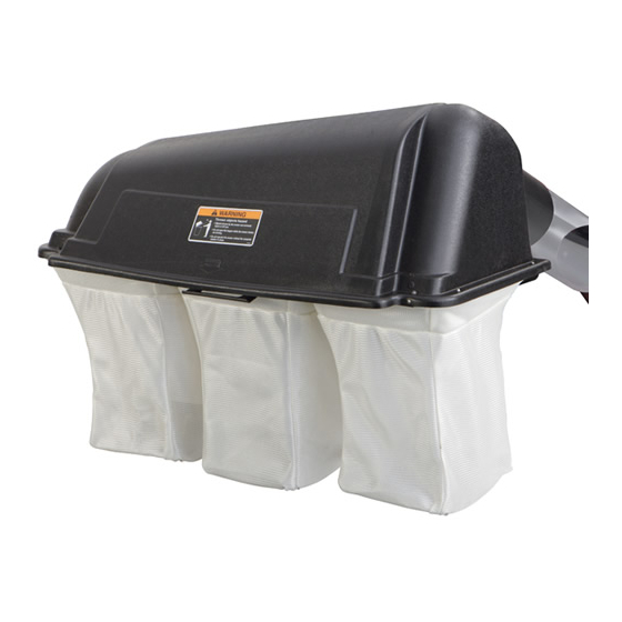
- Page 1 ATTACHMENT OPERATOR’S MANUAL Clean Sweep Triple Catcher Clean Sweep Triple Catcher Mfg. No. Description 1695065 Clean Sweep Triple Catcher 1732613 Rev. 00 Rev. Date 01/2006 TP 100-4268-00-AT-SMN...
- Page 2 THIS PAGE INTENTIONALLY BLANK (FOR PLACEMENT ONLY - DO NOT PRINT)
-
Page 3: Table Of Contents
Safety Rules & Information General Warnings...2 Safety Decals ...2 General Operating Information Mowing with the Triple Catcher...3 Required Accessories...3 After Operation ...3 Initial Turbo Installation - Contents Turbo Installation Group ...4 Install Turbo ...5 Initial Counter Balance & Front Weight Carrier Installation - Counter Balance Installation ...10 Install Front Weight Carrier...10... -
Page 4: Safety Rules & Information
Safety Rules & Information Read these safety rules and follow them closely. Failure to obey these rules could result in loss of control of unit, severe personal injury or death to you, or bystanders, or damage to property or equipment. The trian- in text signifies important cautions or warnings which must be followed. -
Page 5: Mowing With The Triple Catcher
MOWING WITH THE CATCHER Always operate with throttle at full speed when mowing. Grass should be cut often, and not too short. If grass is too long or lush it may be necessary to keep ground speed to a minimum or to cut only half the width of the mower to prevent clogging. -
Page 6: Initial Turbo Installation
Initial Turbo Installation 27 34 Ref. Qty. Description CAPSCREW, Hex Head, 5/16-18 x 1 WASHER, 5/16 SUPPORT, Belt Cover NUT, Hex, Nylon Lock, #10-24 ROD, Deflector SCREW, Truss Head, #10-24 x 3/4 PIVOT ASSEMBLY NUT, Hex Whizlock, 5/16-18 NUT, Nylock, Hex 5/16-18 COVER-BELT 50"... - Page 7 TURBO INSTALLATION Remove Mower Deck Remove the mower deck from the unit (see Operator’s Manual for instructions). Deflector Removal 1. Remove and retain the carriage bolts, washers, lock- washers, and nuts (A, Figure 3) holding the deflector rod to the deck. Remove and discard the deflector rod.
- Page 8 Initial Turbo Installation Install Deflector 1. See Figure 6. Drill four 13/64” holes from the bottom of the deflector at the pre-molded drill points (A, bot- tom of deflector). 2. Attach the deflector to the support rod wire-form using four #10-14 x 3/4 truss head screws and nylock nuts.
- Page 9 Figure 9. Install Idler Assembly A. Idler Assembly. B. Belt Guide C. Capscrew, 5/16-18 x 7/8 Install Idler Assembly & Belt Guide 1. See Figure 9. Remove and discard the two taptite screws from locations (E). 2. Insert two 5/16-18 x 7/8 capscrews (C) through the mower deck and arbor.
-
Page 10: Install Turbo
Initial Turbo Installation 50" Figure 13. Belt Cover Plates A. Belt Cover Plate for 50” Mower B. Belt Cover Plate for 44” Mower WARNING When the turbo blower assembly is removed from the mower deck, the deflector MUST be properly installed. - Page 11 Install Turbo Blower 1. Install the turbo unit by sliding the turbo pivot rod into the pivot bracket at the front edge of the mower deck (A, Figure 17). 2. Tilt the deflector (B) UP. 3. Rotate the turbo unit (C) into position on the dis- charge of the mower deck, and “latch”...
-
Page 12: Initial Counter Balance & Front Weight Carrier Installation
Initial Counter Balance & Weight Carrier Installation Figure 1. Counter Balance Installation COUNTER BALANCE & WEIGHT CARRIER INSTALLATION Counter Balance Installation 1. Remove hair pin (C, Figure 1) from trunnion (B). Remove trunnion (B) from rear deck lift lever (A). Mark or measure trunnion position on rear deck lift lever. -
Page 13: Initial Hitch & Tube Installation
Figure 1. Install Hitch Plate (Flat Style Bumper) A. Hitch Plate D. Locknuts, 1/2-13 B. Heat Shield E. Upper & Lower C. Capscrews Hex, Bumper 1/2-13 x 1-1/4 F. existing Holes HITCH & TUBE INSTALLATION Install Hitch Plate and Back Plate Flat Style Bumper 1. -
Page 14: Install Tubes & Deflector
Initial Hitch & Tube Installation Figure 4. Install Back Plate (Flat Style Bumper shown) A. Back Plate and Support C. Hitch Plate B. Hair Pin D. Rod A. Deflector F. Locknut, 5/16-18 B. Back Plate G. Upper Tube C. Capscrew, H. -
Page 15: Initial Collector Assembly
Figure 1. Assemble Catcher Bags A. Clip B. Cloth Bag C. 5/16-18 x 3/4 Carriage Bolt D. Hanger Bracket COLLECTOR ASSEMBLY Assemble Catcher Bags 1. See Figure 1. Insert the wire hoop (H) through the cloth bag (B). 2. Install the clamp (E) and hanger bracket (D). Secure with two 5/16-18 x 3/4 carriage bolts (C), lockwashers (G) and nuts (F). -
Page 16: Removing The Grass Catcher
Removing & Re-attaching Grass Catcher Figure 1. Remove the Cover A. Cover C. Hinge B. Hinge Pin D. Hair Pin Clip Figure 2. Remove the Bags A. Bags REMOVING & RE-ATTACHING THE GRASS CATCHER Removing the Grass Catcher & Tubes 1. -
Page 17: Reattaching The Grass Catcher
Figure 5. Install Back Plate (Flat Style Bumper shown) A. Back Plate & Support C. Hitch Plate B. Hair Pin D. Rod Re-attaching the Grass Catcher 1. Set the back plate and support (A, Figure 5) onto pins of hitch plate (C). Secure with rod (D) and hair pin (B). - Page 18 M A N U F A C T U R I N G , I N C . 500 N Spring Street / PO Box 997 Port Washington, WI 53074-0997 www.SimplicityMfg.com Simplicity Mfg. Inc. - Snapper Products 535 Macon Street McDonough, GA 30253 www.Snapper.com ©...