Table of Contents
Advertisement
CUTTING WIDTH
ENGINE HP
SERIES DESIGNATION
DRIVE SYSTEM
Thank you for buying a SNAPPER Product! Before operating your machine, read this manual carefully and pay
particular attention to the "IMPORTANT SAFETY INSTRUCTIONS" on Pages 2 & 3. Remember that all power
equipment can be dangerous if used improperly. Also keep in mind that SAFETY requires careful use in
accordance with the operating instructions and common sense!
COPYRIGHT © 2001
SNAPPER INC.
ALL RIGHTS RESERVED
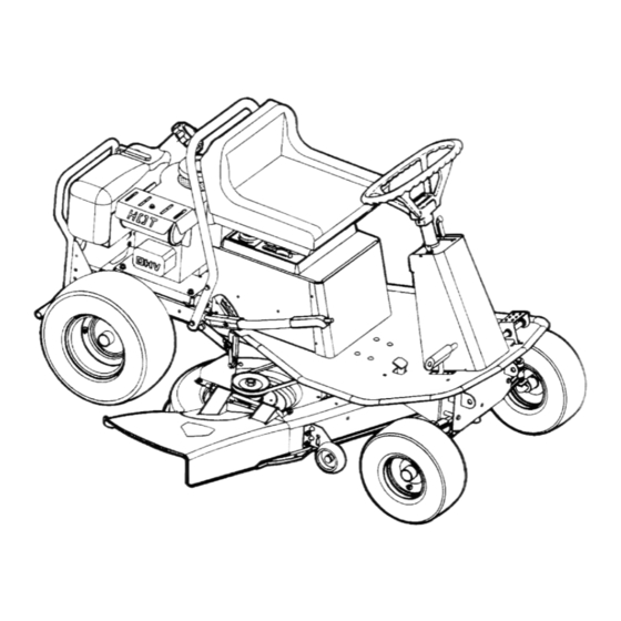
Safety Instructions & Operator's Manual for
REAR ENGINE RIDING MOWER
MODEL NUMBER EXPLANATION
38
145
38 – 38" Cutting Deck
145 – 14.5 HP Engine
1 – Series Designation
HYDRO DRIVE
1
H
B
H – Hydrostatic Drive System
B – Briggs Engine
V – Over Head Valve
E – Electric Start
SERIES 1
MODEL
381451HBVE
V
E
ENGINE OPTIONS
ENGINE MODEL
MANUAL No. 7-2214 (REV. 3, 8/29/01)
ENGINE TYPE
Advertisement
Table of Contents

Related Manuals for Snapper 381451HBVE


Summary of Contents for Snapper 381451HBVE
-
Page 1: Hydro Drive
145 – 14.5 HP Engine 1 – Series Designation Thank you for buying a SNAPPER Product! Before operating your machine, read this manual carefully and pay particular attention to the “IMPORTANT SAFETY INSTRUCTIONS” on Pages 2 & 3. Remember that all power equipment can be dangerous if used improperly. -
Page 2: Important Safety Instructions
If you have any questions pertaining to your machine which your dealer cannot answer to your satisfaction, call or write the Customer Service Department at SNAPPER, McDonough, Georgia 30253. Phone: (1-800-935-2967). -
Page 3: Important Safety Instructions
13. DO NOT test for spark by grounding spark plug next to spark plug hole; spark plug could ignite gas exiting engine. 14. Have machine serviced by an authorized SNAPPER dealer at least once a year and have the dealer install any new safety devices. -
Page 4: Table Of Contents
TABLE OF CONTENTS IMPORTANT SAFETY INSTRUCTIONS... 2-3 TABLE OF CONTENTS ... 4 SECTION 1 - FAMILIARIZATION... 5 SECTION 2 - OPERATING INSTRUCTIONS... 6-11 Pre-start Checklist ... 6 Operators Seat Adjustment ... 6 Starting & Stopping Engine, Blade & Wheel Drive... 7-11 Starting &... -
Page 5: Section 1 - Familiarization
HEIGHT LEVER 1.1 INTRODUCTION This manual has been prepared for the operator’s of the SNAPPER Hydro Rear Engine Rider. Its purpose, aside from recommending standard operating procedures and routine service requirements, is to promote SAFETY through the use of accepted operating practices. Read, Understand and Follow the IMPORTANT SAFETY INSTRUCTIONS on Pages 2 &... -
Page 6: Section 2 - Operating Instructions
Section 2 - OPERATING INSTRUCTIONS 2.1 PRE-START CHECK LIST Make the following checks and perform the service required before each start-up. The hydro transmission on this machine is equipped with a roll release lever. The control can be used to disengage the transmission. -
Page 7: Starting & Stopping Engine, Blade & Wheel Drive
Section 2 - OPERATING INSTRUCTIONS IMPORTANT: This machine hydrostatic drive. The forward and rearward movement and the speed of movement of the machine is controlled by the ground speed control pedal. A small movement of the ground speed pedal can cause the machine to move instantly. - Page 8 Section 2 - OPERATING INSTRUCTIONS 2.3 STARTING & OPERATION 2.3.1. ENGINE (ELECTRIC START) (Continued) 8. Should the battery be too weak to start the engine, Refer to Section “ENGINE (MANUAL START)” to manually start the electric start engine. 2.3.2. ENGINE (MANUAL START) IMPORTANT: When the ignition key is turned to “RUN”, and the recoil handle is pulled, the engine will turn over but will not start unless the clutch/brake...
-
Page 9: Starting & Stopping Mower Blades
Section 2 - OPERATING INSTRUCTIONS 2.3 STARTING & OPERATION 2.3.3. MOWER BLADE 1. With engine running, move engine speed control to the “FAST” position. 2. Move blade control lever forward to the “ON” blade engaged position. See Figure 2.9. 3. Stop blades by moving blade control lever back to the “OFF”... -
Page 10: Parking Brake
3 seconds, the blade brake must be adjusted. Refer to Section “BLADE BRAKE ADJUSTMENT” for adjustment procedures or return the machine to an authorized Snapper dealer for adjustment. DO NOT continue to operate mower until blade brake is adjusted and functioning properly. -
Page 11: Cutting Height Adjustment
Section 2 - OPERATING INSTRUCTIONS 2.4 STOPPING - ENGINE, WHEEL DRIVE, BLADE 2.4.4. PARK BRAKE 1. Engage park brake by depressing clutch/brake control pedal fully and pivot pedal forward to the locked position. Do not park machine on slopes. See Figure 2.14. -
Page 12: Section 3 - Maintenance Instructions
To retain the quality of the Hydro Rear Engine Rider, use genuine SNAPPER replacement parts only. Contact a local SNAPPER dealer for parts and service assistance. For the correct part or information for a particular Hydro Rear Engine Riding Mower, always mention the model and serial number. -
Page 13: Check Mower Blade
Section 3 - MAINTENANCE WARNING DO NOT attempt any adjustments, maintenance, service or repairs with the engine running. STOP engine. STOP blade. Engage parking brake. Remove key. Remove spark plug wire from spark plug and secure away from plug. Engine and components are HOT. -
Page 14: Check Blade Brake
2. The operator leaves the operator position with Blade Control “ON” and/or clutch / brake pedal is released. DO NOT operate machine if interlock system is not functioning properly. Contact your SNAPPER Dealer immediately for assistance. signs 3.2.9. Lubrication - Grease Fittings... -
Page 15: Lubrication - Grease Fittings
Section 3 – MAINTENANCE 3.2.9. Lubrication - Grease Fittings (Continued from previous page) AXLE PIVOT FIGURE 3.8 2. Front axle kingpins, 2-3 shots. See Figure 3.9. KING PIN BUSHING FIGURE 3.9 3. Front wheel bearings, 3-5 shots. See Figure 3.10. WHEEL BEARINGS FIGURE 3.10... -
Page 16: Service - Every 25 Operating Hours
Section 3 – MAINTENANCE 3.3 SERVICE - EVERY 25 OPERATING HOURS 3.3.1. Perform all service required after the first 5 hours of operation – Refer to Section “SERVICE – AFTER FIRST 5 HOURS”. 3.3.2. Check battery electrolyte level. Battery is located under seat. -
Page 17: Section 4- Adjustments And Repair
Section 4 - ADJUSTMENTS & REPAIR WARNING DO NOT attempt any adjustments, maintenance, service or repairs with the engine running. STOP engine. STOP blade. Engage parking brake. Remove key. Remove spark plug wire from spark plug and secure away from plug. Engine and components are HOT. -
Page 18: Mower Blade Drive Belt Adjustment & Replacement
Section 4 - ADJUSTMENTS & REPAIR WARNING DO NOT attempt any adjustments, maintenance, service or repairs with the engine running. STOP engine. STOP blades. Engage parking brake. Remove key. Remove spark plug wire from spark plug and secure away from plug. Engine and components are hot. -
Page 19: Engine To Deck Belt Replacement
Disengage blades. Blades should stop rotating in 3 seconds or less. If blade drive does not function properly recheck adjustments or contact your SNAPPER dealer for assistance. 10. Install cover to seat pedestal. Tighten screws securely. 4.3.2. Engine To Deck Belt Replacement Replace belt if worn, damaged or if belt adjustment does not restore proper function. -
Page 20: Deck Belt Replacement
3 seconds, turn adjustment nut one more turn clockwise. If blade stop time remains over 3 seconds DO NOT OPERATE machine. Contact your local SNAPPER Dealer for assistance. DO NOT operate machine until blade brake is adjusted and functioning properly. -
Page 21: Mower Deck Level Adjustment
Section 4 - ADJUSTMENTS & REPAIR WARNING DO NOT attempt any adjustments, maintenance, service or repairs with the engine running. STOP engine. STOP blade. Engage parking brake. Remove key. Remove spark plug wire from spark plug and secure away from plug. Engine and components are HOT. -
Page 22: Battery Removal, Replacement, Service
2 hours with no acid leakage. Failure to use a genuine Snapper battery or installing the Snapper battery incorrectly will result in damage to your machine. The Snapper battery must be installed with the battery caps towards the front of the machine and the terminals towards the rear. -
Page 23: Battery Storage
Section 4 - ADJUSTMENTS & REPAIR 4.8.2. Battery Installation (Continued) 3. Connect negative (-) cable (black) last, to negative terminal (-) on battery using bolt and nut. Apply a small amount of grease over terminals to prevent corrosion. See Figure 4.16. FRONT FIGURE 4.16 4. - Page 24 Section 4 - ADJUSTMENTS & REPAIR 4.8.6. Battery Testing State of Charge 100% Charged w/ Sulfate Stop 100% Charged 75% Charged 50% Charged 25% Charged 0% Charged Battery Condition Chart Syringe Hydrometer Digital Voltmeter 1.280 1.265 1.210 1.160 1.120 Less than 1.100 Less than 11.80v Five Ball Hydrometer 12.80v...
-
Page 25: Troubleshooting
2. Move engine speed control to “CHOKE” position. 3. Place spark plug wire onto spark plug. 4. Contact authorized SNAPPER dealer. 5. Engage park brake. 6. Turn ignition switch to the RUN position. 1. Fill fuel tank with fresh fuel to proper level. - Page 26 2. Leaking engine block. TROUBLESHOOTING (Continued on Previous Page PROBABLE CAUSE CORRECTIVE ACTION 1. Contact authorized SNAPPER dealer. 2. Install new engine to transmission belt. 3. Move control to DRIVE position. 4. Release parking brake. 1. Move lever to the “ON” position.
-
Page 27: Maintenance Schedule
SUBJECT SERVICE TO BE PERFORMED Engine Check Oil Level Engine Initial Oil Change Engine Periodic Oil Change Air Pre-Cleaner Service Sponge Pre- Cleaner Element Air Cleaner Replace Element Spark Plug Replace Plugs Fuel Filter Replace Filter Engine Cooling Clean Shrouds & Fins System Transmission Clean fan &... -
Page 28: Warranty
For three (3) years from purchase date for the original purchaser's residential, non-commercial use, SNAPPER, through any authorized SNAPPER dealer will replace, free of charge (except for taxes where applicable), any part or parts found upon examination by the factory at McDonough, Georgia, to be defective in material or workmanship or both. -
Page 29: Primary Maintenance
PRIMARY MAINTENANCE... - Page 30 PRIMARY MAINTENANCE...
- Page 31 PRIMARY MAINTENANCE...
-
Page 32: Primary Maintenance
PRIMARY MAINTENANCE... - Page 33 SERVICE NOTES ______________________________________________________________________________ ______________________________________________________________________________ ______________________________________________________________________________ ______________________________________________________________________________ ______________________________________________________________________________ ______________________________________________________________________________ ______________________________________________________________________________ ______________________________________________________________________________ ______________________________________________________________________________ ______________________________________________________________________________ ______________________________________________________________________________ ______________________________________________________________________________ ______________________________________________________________________________ ______________________________________________________________________________ ______________________________________________________________________________ ______________________________________________________________________________ ______________________________________________________________________________ ______________________________________________________________________________ ______________________________________________________________________________ ______________________________________________________________________________ ______________________________________________________________________________ ______________________________________________________________________________ ______________________________________________________________________________ ______________________________________________________________________________ ______________________________________________________________________________ ______________________________________________________________________________ ______________________________________________________________________________ ______________________________________________________________________________ ______________________________________________________________________________ ______________________________________________________________________________ ______________________________________________________________________________ ______________________________________________________________________________ ______________________________________________________________________________ ______________________________________________________________________________ ______________________________________________________________________________ ______________________________________________________________________________ ______________________________________________________________________________ ______________________________________________________________________________ ______________________________________________________________________________ ______________________________________________________________________________ ______________________________________________________________________________...
- Page 34 Read, Understand, and Follow all warnings and instructions in this manual, the engine manual, and on the machine, engine and attachments. If you have any questions about your Snapper product, contact your local authorized Snapper dealer or contact Snapper Customer Service at Snapper, McDonough, GA.