Advertisement
Table of Contents
Advertisement
Table of Contents

Related Manuals for Sonance GARDEN SERIES


Summary of Contents for Sonance GARDEN SERIES
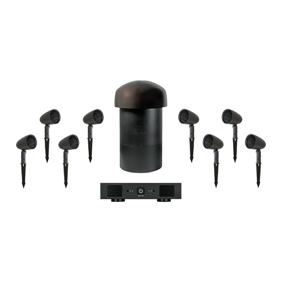
- Page 1 SONANCE GARDEN SERIES SGS SYSTEM I N ST R U C T I O N M A N UA L...
-
Page 2: Table Of Contents
TABLE OF CONTENTS Design and Features Introduction Box Contents Speaker Layout Planning Types of Wire Speaker Installation Connecting the Speakers Recommended Tools Speaker Wire Connection Subwoofer Wire Connection Specifications Warranty... -
Page 3: Design And Features
In some cases you may want to place the subwoofer closer to your SYSTEM. When properly installed, this system will provide you with primary listening position or add a second Sonance Garden Series years of outdoor entertainment pleasure. To get the most out of subwoofer. -
Page 4: Types Of Wire
SR 2-125 Amplifier Left and Right Left Right Left Right Left Right Left Right Figure 3: Sonance Garden Series SGS System Wiring Diagram 8 Ohms... -
Page 5: Recommended Tools
Recommended Tools Speaker Wire Connection Connecting the speakers using 14/4 direct burial speaker wire. 1. Pull the 14/4 wire on the spool to the furthest speaker location. Leave the wire attached to the spool until the last speaker has been connected. 2. -
Page 6: Speaker Wire Connection
Connecting the Speakers Using a 2-Conductor Wire or Low Voltage Lighting Wire 1. Pull the first pair of 2-conductor wire to the furthest speaker location, leaving it connected to the spool near the amplifier. 2. Starting at the furthest speaker and every other speaker that follows, create a loop of wire approximately 6”... -
Page 7: Subwoofer Wire Connection
If the speakers are operating properly, refill the manner as the satellites speakers (see Figure 6). wire trench and enjoy your new Sonance Garden Series System. IMPORTANT: THE SUBWOOFER HAS DUAL VOICE COILS, ONE FOR THE LEFT CHANNEL AND ONE FOR THE RIGHT CHANNEL,, IT IS CRITICAL THAT THE POSITIVE AND NEGATIVE WIRES BE CONNECTED CORRECTLY FOR BOTH CHANNELS. -
Page 8: Specifications
24.8” x 15” (630mm x 381mm) Shipping Weight: 40 lbs (19kg) Speaker Wire Recommendations: 18 gauge - up to 100 ft. (30m) 16 gauge - up to 150 ft. (45m) 14 gauge - up to 280 ft. (85m) CAD files available for download at www.sonance.com... -
Page 9: Warranty
SPECIFICALLY EXCLUDED. No one is authorized to make or modify any warranties on behalf of Sonance. The warranty stated above is the sole and exclusive remedy and Sonance’s performance shall constitute full and final satisfaction of all obligations, liabilities and claims with respect to the Product.