Kenwood NX-720 Service Manual
Vhf digital transceiver
Hide thumbs
Also See for NX-720:
- Service manual (127 pages) ,
- Instruction manual (24 pages) ,
- Technical details (2 pages)
Table of Contents
Advertisement
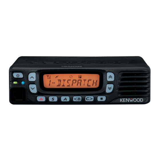
VHF DIGITAL TRANSCEIVER
NX-720(G)/720
SERVICE MANUAL
REVISED
Modular jack
(E58-0535-05)
General ....................................................2
System Set-Up .........................................4
Realignment ...........................................4
Installation ............................................7
Disassembly For Repair .....................9
Circuit Description ...........................11
Components Description ................17
Parts List ...............................................19
Exploded View ......................................29
Trouble Shooting ..............................30
Adjustment ...........................................34
This product complies with the RoHS directive for the European market.
Key top
(K29-9479-01)
CONTENTS
Terminal Function .............................56
Display Unit (X54-3830-10) ...............60
Tx-Rx Unit (X57-8230-1X)....................62
Interconnection Diagram ...............66
Schematic Diagram ............................67
Block Diagram .....................................78
Level Diagram ......................................81
KRA-40 ...................................................82
Specifications ......................................83
© 2012-12 PRINTED IN JA PAN
B53-7039-10 ( Y ) PDF
Panel assy
Badge
(A62-1200-03)
(B43-1675-04)
This product uses Lead Free solder.
Advertisement
Table of Contents

Related Manuals for Kenwood NX-720


Summary of Contents for Kenwood NX-720
- Page 1 VHF DIGITAL TRANSCEIVER NX-720(G)/720 SERVICE MANUAL REVISED © 2012-12 PRINTED IN JA PAN B53-7039-10 ( Y ) PDF Key top Modular jack Panel assy Badge (K29-9479-01) (E58-0535-05) (A62-1200-03) (B43-1675-04) CONTENTS GENERAL ............2 TERMINAL FUNCTION ......56 SYSTEM SET-UP .........4 PC BOARD REALIGNMENT ...........4...
-
Page 2: General
Disclaimer While every precaution has been taken in the preparation Transceivers containing AMBE+2™ Vocoder: of this manual, JVC KENWOOD Corporation assumes no The AMBE+2™ voice coding technology is embedded in responsibility for errors or omissions. Neither is any liability the fi rmware under the license of Digital Voice Systems, Inc. - Page 3 NX-720(G)/720 GENERAL 3-3. Radio 4-2. Radio location The universal mount bracket allows the radio to be Select a convenient location for your control station radio mounted in a variety of ways. Be sure the mounting surface which is as close as practical to the antenna cable entry is adequate to support the radio’s weight.
-
Page 4: System Set-Up
Choose the type of transceiver 136~174 NX-720(G)/720 See page 4. Transceiver programming A personal computer, programming interface (KPG-46A/46U), and FPU (programming software) are required for programming. (Option: NX-720(G) only) KRA-40 GPS active antenna KCT-60 (Option) Connection cable See page 7. (Option) *Only when required. - Page 5 NX-720(G)/720 REALIGNMENT 5-2. Connection procedure 1. Connect the transceiver to the computer using the inter- KPG-46A or KPG-46U face cable. Tuning cable (E30-3383-05) Note: • You must install the KPG-46U driver in the computer to use the USB programming interface cable (KPG-46U).
-
Page 6: Clone Mode
NX-720(G)/720 REALIGNMENT 6-4. Function 3. If the [ ] and [ ] keys is pressed while “CLONE LOCK” is displayed, numbers (0 to 9) are displayed fl ashing. When If you press the [ key while “FIRM PRG” is displayed, you press the [ ] key, the currently selected number is the checksum is calculated, and a result is displayed.If you... -
Page 7: Installation
NX-720(G)/720 INSTALLATION 2-1. Installation Procedure 1. Connection Cable (KCT-60: Option) 1. Remove the ACC. cap on the rear of the transceiver. The KCT-60 connection cable kit is used to connect the 2. Connect the D-sub connector of the KCT-60 to the D-sub transceiver to a Horn alert cable, KCT-18 (Ignition sense 15-pin terminal of the transceiver. - Page 8 NX-720(G)/720 INSTALLATION Remove the R664, R635, R662, R659, R658 and R632 4. External Speaker (Option) chip jumpers and solder the chip jumpers to R666, R633, 4-1. KES-5 R665, R663, R660 and R630. External speaker KES-5 can be installed for KCT-60.
-
Page 9: Disassembly For Repair
NX-720(G)/720 DISASSEMBLY FOR REPAIR 3. Disconnect the fl at cable from connector of the panel as- 1. Disassembly Procedure sembly. 1. Remove the cabinet, top packing and shielding plate of the transceiver. Cabinet Flat cable 4. Hook the finger to hole and while pulling the speaker holder to this side, expand the panel side of a to c , and remove the speaker holder from the front panel. - Page 10 NX-720(G)/720 DISASSEMBLY FOR REPAIR Note: 2. When mounting the panel assembly, pass the fl at cable through the hole of the chassis as shown below then con- When you supply power to the TX-RX PCB after remov- nect the fl at cable to connector of the panel assembly.
-
Page 11: Circuit Description
NX-720(G)/720 CIRCUIT DESCRIPTION 1. Overview 3. Receiver System The NX-720 is a VHF Mobile transceiver designed to 3-1. RF circuit operate in the frequency range of 136 to 174MHz. The unit An incoming RF signal from the antenna terminal is... - Page 12 NX-720(G)/720 CIRCUIT DESCRIPTION 3-3. Audio amplifi er circuit 4-1. Audio Band Circuit Audio processing (high-pass filter, low-pass filter, de- The signal from the microphone is amplifi ed by IC703 (1/2) emphasized and so on) in FM mode and decoding in NXDN and limited by the AGC circuit composed of D703, D704, mode are processed by the DSP (IC502).
- Page 13 NX-720(G)/720 CIRCUIT DESCRIPTION 5-3. PLL IC (IC2) 5. PLL Frequency Synthesizer The PLL IC compares the differences in phases of the 5-1. TCXO (X1) VCO oscillation frequency and the TCXO reference fre- The TCXO (X1) generates a reference frequency of quency, returns the difference to the VCO CV terminal and 16.8MHz for the PLL frequency synthesizer.
- Page 14 NX-720(G)/720 CIRCUIT DESCRIPTION 6-5. DSP 6. Control Circuit The DSP circuit consists of a DSP (IC502) and process- The control circuit consists of the ASIC (IC507) and its es the baseband signal. The DSP operates on an external peripheral circuits. IC507 mainly performs the following: clock of 18.432MHz (the same as the IC507), the I/O section...
- Page 15 NX-720(G)/720 CIRCUIT DESCRIPTION Fig. 7 Power supply circuit...
- Page 16 NX-720(G)/720 CIRCUIT DESCRIPTION 8. Signaling Circuit 8-1. Encode (QT/DQT/DTMF/2-tone/5-tone/MSK) Each signaling data signal of the QT, DQT, DTMF, 2-tone, 5-tone and MSK is generated by the DSP circuit, super- posed on a modulation signal and output from the ASIC (IC507). Each deviation of the TX QT, DQT, DTMF, 2-tone,...
-
Page 17: Components Description
NX-720(G)/720 COMPONENTS DESCRIPTION Display unit (X54-3830-10) TX-RX unit (X57-8230-1X) Ref. No. Part Name Description Ref. No. Part Name Description LCD driver AVR (80C) Transistor TX/Busy LED switch PLL system Transistor TX/Busy LED switch DC AMP (CV/Assist) Transistor LCD backlight switch... - Page 18 NX-720(G)/720 COMPONENTS DESCRIPTION Ref. No. Part Name Description Ref. No. Part Name Description Variable capaci- Transistor DC switch (Assist) RX VCO frequency control tance diode DC switch (Assist) Variable capaci- TX VCO frequency control tance diode Transistor Ripple fi lter...
-
Page 19: Parts List
TX-RX UNIT(FOR SERVICE) RK73HB1J000J CHIP R 1/16W RK73HB1J473J CHIP R 1/16W R24 ,25 RK73HB1J332J CHIP R 3.3K 1/16W RK73HB1J472J CHIP R 4.7K 1/16W RK73FB2B121J CHIP R 1/8W RK73FB2B221J CHIP R 1/8W R34 -37 RK73GB2A271J CHIP R 1/10W GE: NX-720(G) E: NX-720... - Page 20 CHIP C 220PF C152 C92-0875-05 ELECTRO 47UF 25WV CC73HCH1H181J CHIP C 180PF C154 CK73HB1E223K CHIP C 0.022UF K CC73HCH1H390G CHIP C 39PF C155 CK73HB1H471K CHIP C 470PF CC73HCH1H080B CHIP C 8.0PF C156 CC73HCH1H101J CHIP C 100PF GE: NX-720(G) E: NX-720...
- Page 21 100PF C259 CK73HB1H102K CHIP C 1000PF C260 CC73HCH1H180G CHIP C 18PF C432 CK73GB1H104K CHIP C 0.10UF C261 CC73HCH1H560J CHIP C 56PF C433,434 CK73FB1E475K CHIP C 4.7UF C262 CK73HB1H102K CHIP C 1000PF C435 CK73GB1C225K CHIP C 2.2UF GE: NX-720(G) E: NX-720...
- Page 22 CK73HB1H103K CHIP C 0.010UF K C553 CK73HB1A105K CHIP C 1.0UF C732 CK73HB1H102K CHIP C 1000PF C555,556 CK73HB1H103K CHIP C 0.010UF K C733 CK73FB1E475K CHIP C 4.7UF C558 CK73HB1A104K CHIP C 0.10UF C734 CK73HB1H472K CHIP C 4700PF GE: NX-720(G) E: NX-720...
- Page 23 L213 L41-1085-14 SMALL FIXED INDUCTOR(100NH) CN203-206 E23-1278-05 TERMINAL CN514 E40-6847-05 FLAT CABLE CONNECTOR L214 L40-1275-92 SMALL FIXED INDUCTOR(12NH) CN801 E04-0410-05 PIN SOCKET(3P) L215,216 L41-3378-14 SMALL FIXED INDUCTOR(33NH) J501 E58-0536-05 D-SUB SOCKET(15P) L220 L40-2785-92 SMALL FIXED INDUCTOR(270NH) GE: NX-720(G) E: NX-720...
- Page 24 CHIP R 1/16W R142 RK73HB1J000J CHIP R 1/16W RK73HB1J103J CHIP R 1/16W RK73HB1J106J CHIP R 1/16W R143 RK73HB1J104J CHIP R 100K 1/16W R145 RK73GB2A000J CHIP R 1/10W RK73HB1J470J CHIP R 1/16W R146 RK73HB1J393J CHIP R 1/16W GE: NX-720(G) E: NX-720...
- Page 25 CHIP R 1.0K 1/16W R338 RK73HB1J473J CHIP R 1/16W R518 RK73HB1J101J CHIP R 1/16W R339 RK73HB1J153J CHIP R 1/16W R519 RK73HB1J000J CHIP R 1/16W R340 RK73HB1J274J CHIP R 270K 1/16W R521,522 RK73HB1J104J CHIP R 100K 1/16W GE: NX-720(G) E: NX-720...
- Page 26 R662 RK73GB2A000J CHIP R 1/10W R664 RK73GB2A000J CHIP R 1/10W R787 RK73HB1J123J CHIP R 1/16W R667 RK73GB2A101J CHIP R 1/10W R796,797 RK73GB2A000J CHIP R 1/10W R668 RK73HB1J471J CHIP R 1/16W R800 RK73HB1J104J CHIP R 100K 1/16W GE: NX-720(G) E: NX-720...
- Page 27 DIODE Q201 3SK318 GE: NX-720(G) If a part reference number is listed in a shaded box, that part does not come with the PCB. E: NX-720 Note 1: This part cannot be replaced. Therefore, this part is not supplied as a service part.
- Page 28 Q504 LTC014TEBFS8 TRANSISTOR Q701 FK330301 Q702 KTC4075E(Y,GR) TRANSISTOR Q703 2SA1832(GR)F TRANSISTOR Q704 2SC4738(GR)F TRANSISTOR Q705,706 SSM3J15FS Q708 LTC014EEBFS8 TRANSISTOR Q709 SSM6N37FE ERTJ0EV104H THERMISTOR TH101 ERTJ0EV104H THERMISTOR TH103 ERTJ0EV104H THERMISTOR TH701 ERTJ0EV104H THERMISTOR A801 W02-3768-05 GPS MODULE GE: NX-720(G) E: NX-720...
-
Page 29: Exploded View
NX-720(G)/720 EXPLODED VIEW : N30-2605-48(M2.6x5) : N67-3008-48(M3x8) : N87-2608-48(Ø2.6x8) J501 J701 IC102 IC714 TX-RX unit Cx13 R171 (W/O GPS type) (G type) Display unit Parts with the exploded numbers larger than 700 are not supplied. If a part reference number is listed in a box on the exploded view of the PCB, that part does not come with the PCB. -
Page 30: Trouble Shooting
NX-720(G)/720 TROUBLE SHOOTING Fault Diagnosis of the BGA (Ball Grid Array) IC ■ Overview A fl owchart for determining whether or not the transceiver can be powered on (the LCD does not function even if the power switch is turned on) due to broken BGA parts. - Page 31 NX-720(G)/720 TROUBLE SHOOTING ● Checking the signal output from When a normal value is confirmed. the ASIC by software control When an abnormal value is confirmed. Points to be checked Normal voltage Remove R407. If the ASIC side is 0V, SBC R407 3.3V...
- Page 32 KRA-40 is defective. Replacing TX-RX Unit ■ TX-RX unit Information Model Name Frequency Range [MHz] Original TX-RX unit Number For Service TX-RX unit Number NX-720(G) (GPS model): E 136 - 174 X57-8230-10 X57-8230-12 NX-720: E 136 - 174 X57-8230-11 X57-8230-13...
- Page 33 Type : Kx the Trunking System following the new ESN. The same number as the KENWOOD ESN • When a new printed circuit board is used, the KENWOOD label is written. ESN changes, as does the Transceiver Information dis- NXDN ESN/MPT...
-
Page 34: Adjustment
NX-720(G)/720 ADJUSTMENT ■ Key operation Controls “ ” not appears on the LCD display Function Display Power Volume Channel switch Up/Down key Up/Down key [ ]/[ ] Test channel up/down Channel No. Squelch level Push: Squelch level up Hold: Squelch off... - Page 35 NX-720(G)/720 ADJUSTMENT ■ Frequency and Signaling • LED indicator The transceiver has been adjusted for the frequencies Red LED Lights during transmission. shown in the following table. When required, readjust them Green LED Lights when there is carrier. following the adjustment procedure to obtain the frequencies you want in actual operation.
-
Page 36: Key Operation
NX-720(G)/720 ADJUSTMENT ■ Key operation • NXDN mode signaling Function RAN1 RAN1 Push Hold (1 second) None [ ]/[ ] Adjustment value up/down RAN1 Maximum Deviation Pattern 20Hz/2kHz (During transmis- sion in balance adjustment) FSW+PN9 (PC test mode None only) - Page 37 NX-720(G)/720 ADJUSTMENT ■ Adjustment item supplement Adjustment Item Description The lock voltage of VCO (Receive) is adjusted. Receive Assist This item must be adjusted before all adjustment items for receiver section are adjusted. This item can be adjusted only in PC Test Mode.
- Page 38 NX-720(G)/720 ADJUSTMENT ■ Adjustment item and Adjustment range (Analog (Analog (Analog (NXDN (NXDN Adjustment Panel Adjust item Order Wide 5k) Wide 4k) Narrow) Narrow) Very Narrow) item tuning test Number Adjustment range 9 point ADJ Common ✓ Receive Assist Section 2...
- Page 39 NX-720(G)/720 ADJUSTMENT (Analog (Analog (Analog (NXDN (NXDN Adjustment Panel Adjust item Order Wide 5k) Wide 4k) Narrow) Narrow) Very Narrow) item tuning test Number Adjustment range - *1 Receiver ✓ ✓ RSSI Reference Section 4 1~256 - *1 Receiver ✓...
- Page 40 NX-720(G)/720 ADJUSTMENT ] hold LTR Deviation LTR Deviation Wide Narrow ] press ] hold DTMF Deviation DTMF Deviation Wide DTMF Deviation Wide Narrow DTMF DTMF DTMF ] press ] hold Wide Single Tone Deviation Single Tone Deviation Wide Single Tone Deviation...
- Page 41 NX-720(G)/720 ADJUSTMENT Test Equipment Required for Alignment Test Equipment Major Specifi cations Frequency Range 100 to 520MHz Modulation Frequency modulation and external modulation 1. Standard Signal Generator Output –127dBm/0.1µV to greater than –20dBm/22.4mV (SSG) When performing the Frequency adjustment, the following accuracy is necessary.
- Page 42 NX-720(G)/720 ADJUSTMENT Radio check Section Condition Measurement Adjustment Specifi cations/ Item Test- Remarks Panel test mode PC test mode Unit Terminal Unit Parts Method equipment 1. Frequency 1) CH-Sig: 1-1 1) Test Channel f. counter Check an internal +/-0.25ppm check...
- Page 43 NX-720(G)/720 ADJUSTMENT Condition Measurement Adjustment Specifi cations/ Item Test- Termi- Remarks Panel test mode PC test mode Unit Unit Parts Method equipment 5. Sensitivity 1) CH-Sig: 1-1 1) Test Channel Check 12dB SINAD or check SSG output Channel: 1 AF VM Ext.SP...
- Page 44 NX-720(G)/720 ADJUSTMENT Condition Measurement Adjustment Specifi cations/ Item Test- Remarks Panel tuning mode PC test mode Unit Terminal Unit Parts Method equipment The Frequency 4. Frequency 1) Adj item: [PC test mode] [PC test mode] adjustment can be [Frequency] Press [Start] but- The value of “IF20”...
- Page 45 NX-720(G)/720 ADJUSTMENT Condition Measurement Adjustment Specifi cations/ Item Test- Remarks Panel tuning mode PC test mode Unit Terminal Unit Parts Method equipment 2. High 1) Adj item: [HPWR] 1) TEST CH: Power [Panel 25.0W ±1.0W Transmit Adjust: [] Low, Low’, Center,...
- Page 46 NX-720(G)/720 ADJUSTMENT Condition Measurement Adjustment Specifi cations/ Item Test- Remarks Panel tuning mode PC test mode Unit Terminal Unit Parts Method equipment 4. Maximum 1) Adj item: [NDEV] 1) Adj item: [Maximum Deviation [Panel Write Reference 1311~1363Hz Deviation Adjust: []...
- Page 47 NX-720(G)/720 ADJUSTMENT Condition Measurement Adjustment Specifi cations/ Item Test- Remarks Panel tuning mode PC test mode Unit Terminal Unit Parts Method equipment 6. QT 1) Adj item: [QT] 1) Adj item: [QT Deviation [Panel Write the value 0.6kHz±0.05kHz Deviation *4 Adjust: [..]...
- Page 48 NX-720(G)/720 ADJUSTMENT Condition Measurement Adjustment Specifi cations/ Item Test- Remarks Panel tuning mode PC test mode Unit Terminal Unit Parts Method equipment 8. LTR 1) Adj item: [LTR] 1) Adj item: [LTR Deviation [Panel Write the value 0.75kHz±0.05kHz Deviation *4 Adjust: [.]...
- Page 49 NX-720(G)/720 ADJUSTMENT Condition Measurement Adjustment Specifi cations/ Item Test- Remarks Panel tuning mode PC test mode Unit Terminal Unit Parts Method equipment 10. Single 1) Adj item: [TONE] 1) Adj item: [Single Deviation Panel Write the value 2.40kHz±0.05kHz Tone Adjust: [..]...
- Page 50 NX-720(G)/720 ADJUSTMENT ■ Necessary Deviation adjustment item for each signaling and mode The following shows the necessary adjustment items for each signaling deviation. Please read the following table like the following example. In the case of the signaling “QT (Wide 5k/Wide 4k)”, this signaling is composed of three elements [Balance, Maximum Devia- tion (Analog Wide 5k/Wide 4k) and QT Deviation (Wide 5k/Wide 4k)].
- Page 51 NX-720(G)/720 ADJUSTMENT Condition Measurement Adjustment Specifi cations/ Item Test- Remarks Panel tuning mode PC test mode Unit Terminal Unit Parts Method equipment This adjustment 2. Sensitivity 1) Adj item: [PC test Write the value as Increase the adjust- can be performed...
- Page 52 NX-720(G)/720 ADJUSTMENT Condition Measurement Adjustment Specifi cations/ Item Test- Remarks Panel tuning mode PC test mode Unit Terminal Unit Parts Method equipment 4. RSSI 1) Adj item: [RRSS] 1) Adj item: [Panel tuning mode] Adjust with the ana- reference Adjust: []...
- Page 53 NX-720(G)/720 ADJUSTMENT Condition Measurement Adjustment Specifi cations/ Item Test- Remarks Panel tuning mode PC test mode Unit Terminal Unit Parts Method equipment *6: Because Open squelch (NXDN Narrow) is adjusted by adjusting Open squelch (Analog Narrow), it is not necessary to adjust Open squelch (NXDN Narrow).
- Page 54 NX-720(G)/720 ADJUSTMENT Condition Measurement Adjustment Specifi cations/ Item Test- Remarks Panel tuning mode PC test mode Unit Terminal Unit Parts Method equipment 7. High RSSI 1) Adj item: [HRSS] 1) Adj item: [Panel tuning mode] at -80dBm Adjust: [] [High RSSI (Analog Ext.SP...
- Page 55 NX-720(G)/720 ADJUSTMENT Condition Measurement Adjustment Specifi cations/ Item Test- Remarks Panel tuning mode PC test mode Unit Terminal Unit Parts Method equipment 8. Squelch 1) Adj item: [SQLT] 1) Adj item: [Panel tuning mode] “Squelch (Tight)” (Tight) Adjust: [] [Tight Squelch AF VM Ext.SP...
-
Page 56: Terminal Function
NX-720(G)/720 TERMINAL FUNCTION Display unit (X54-3830-10) TX-RX unit (X57-8230-1X) Pin No. Name Function Pin No. Name Function CN1 (to TX-RX unit CN514) CN514 (to Display unit CN1) Battery voltage DC supply Battery voltage DC supply Battery voltage DC supply Battery voltage DC supply SP–... - Page 57 NX-720(G)/720 TERMINAL FUNCTION 8pin Modular Connector Specifi cation Signal Description/port type Item and Condition Unit Note Name Type Digital CMOS output This parameter depends on Bat- Output Voltage tery voltage. Power Switched B output Output Current Ground Allowable Current Value...
- Page 58 NX-720(G)/720 TERMINAL FUNCTION Signal Description Item and Condition Unit Note Name Type Output Level 0.28 Vp-p DETO FM detector output Coupling Capacitor Allowable Load Analog Output Level 0.24 Vp-p RX Audio output Coupling Capacitor Allowable Load Input Voltage Range 1.98...
- Page 59 NX-720(G)/720 TERMINAL FUNCTION Signal Description Item and Condition Unit Note Name Type -0.5 FNC6 I/O Digital Programmable I/O VOH (Io=-1.5mA) VOL (Io=1.5mA) Output Voltage 5.25 50MC Power 5V DC Power supply Output Current Input Voltage Analog Horn alert signal input...
- Page 60 NX-720(G)/720 PC BOARD DISPLAY UNIT (X54-3830-10) Component side view (J79-0345-09) POWER HOOK DISPLAY UNIT (X54-3830-10) Foil side view (J79-0345-09)
- Page 61 NX-720(G)/720 PC BOARD DISPLAY UNIT (X54-3830-10) Component side view (J79-0345-09) Ref. No. Address Component side Layer 1 Layer 2 ■ Foil side J79-0345-09 DISPLAY UNIT (X54-3830-10) Foil side view (J79-0345-09) Ref. No. Address Component side Layer 1 Layer 2 Foil side...
- Page 62 NX-720(G)/720 PC BOARD TX-RX UNIT (X57-8230-1X) Component side view (J79-0343-09) J501 J701 EXT.SP CN804 C815 L806 C816 CN720 R821 R641 R643 F501 CN802 IC801 R637 R835 R844 R674 C660 R639 R673 R638 C646 CN803 C645 D601 A801 Q504 C633 C403...
- Page 63 NX-720(G)/720 PC BOARD TX-RX UNIT (X57-8230-1X) Component side view (J79-0343-09) Ref. No. Address Ref. No. Address Q702 Q703 IC103 Q704 IC102 IC201 Q705 IC303 Q706 IC402 Q708 IC404 Q709 IC409 IC509 D101 IC511 D102 IC512 D110 IC515 D202 C125 R120...
- Page 64 NX-720(G)/720 PC BOARD TX-RX UNIT (X57-8230-1X) Foil side view (J79-0343-09) Ref. No. Address Ref. No. Address Q502 IC301 Q503 IC304 IC401 IC405 R171 L114 IC406 IC407 IC408 R139 IC501 IC502 C163 IC503 IC504 IC506 IC507 R148 C158 IC508 R142 IC513...
- Page 65 NX-720(G)/720 PC BOARD TX-RX UNIT (X57-8230-1X) Foil side view (J79-0343-09) C632 Q502 R822 D705 D706 R667 R405 R406 C413 C788 C471 Q403 Q401 C409 C430 C434 C119 C121 L130 L104 L106 C433 C628 C629 R103 C118 IC516 C437 C457 R425...
-
Page 66: Interconnection Diagram
NX-720(G)/720 INTERCONNECTION DIAGRAM OUT1 POWERGND OUT2 FILTER PREGND RFINPUT GATEBIAS DRAINBIAS RFOUTPUT 1-42 B38-0936-05... -
Page 67: Schematic Diagram
NX-720(G)/720 SCHEMATIC DIAGRAM TX-RX UNIT(X57-8230-1X) B-BUS CN423 R:13.2V T(25W):12.8V DC/DC Converter(50M) D407 13.2V DC/DC BATTERY Converter(50M) CN422 SHDN 5.02V D407 RB520SM-30 L404 BooST Surge Reverse Protection Current Prevention IC405 L405 LT1616ES6-PBF 22uH D406 DC/DC Converter AVR(33A) CN421 AVR(33M) 4.98V R418 3.3V... - Page 68 NX-720(G)/720 SCHEMATIC DIAGRAM TX-RX UNIT (X57-8230-1X) B-BUS B-BUS FSX0 CLKX0 A-BUS A-BUS D-BUS D-BUS C-BUS C-BUS R526 100k CP513 100kX4 CP507 100kX4 CN541 CN542 CP514 C533 15MDSP 100kX2 CN502 CLKoUT DGND CN503 D[15] CN540 D[15] 33MDSP D[14] D[14] D[13] GPIo0...
- Page 69 NX-720(G)/720 SCHEMATIC DIAGRAM TX-RX UNIT (X57-8230-1X) B-BUS B-BUS FSX0 FSX0 CLKX0 CLKX0 A-BUS D-BUS C-BUS L506 IC506 (MCLK) C542 18.432MHz 3.3V R555 0.01u INHN SM5023CNDH-G Buffer AMP(Clock) R556 A4 XTALI XTALo DSPCK GPSDET /HINT USRCKI A[0] ADD0 A[1] ADD1 A[2]...
- Page 70 NX-720(G)/720 SCHEMATIC DIAGRAM TX-RX UNIT (X57-8230-1X) B-BUS B-BUS FSX0 CLKX0 C543 0.1u IC508 TC7SH08FU-F 18.423MHz X501 AND Gate L77-3015-05 R568 IC301 TC7SH08FU-F R567 BSHIFT oUTPUT R569 oUTY AND Gate CN523 oUTY C706 R707 MIC2 1.8k 0.1u C718 DGND2 0.1u DGND1 0.1u...
- Page 71 NX-720(G)/720 SCHEMATIC DIAGRAM TX-RX UNIT (X57-8230-1X) B-BUS AF AMP Q703,704 Q704 D703 MIC AGC 2SC4738(GR)F D703,704 IC714 DA3S101F R775 AF Detector 5.6k 6.5V 1.44V 6.3V Bias R823 C806 SPAF MIC2 Bias 1.44V D704 DA3S101F R819 C797 R777 2.2k 0.22u R811...
- Page 72 NX-720(G)/720 SCHEMATIC DIAGRAM ✽ 1 X57-823X-XX A801 CN801 C809 C814 C815 C816 C820 C821 C822 C823 C824 C825 C826 L802 R561 R802 R835 R839 R842 R843 R844 IC801 D801 D802 L801 L805 L806 0-10 NX-720(G) 0-11 NX-720 TX-RX UNIT (X57-8230-1X) ✽...
- Page 73 NX-720(G)/720 SCHEMATIC DIAGRAM TX-RX UNIT (X57-8230-1X) THP1 THP1 /T_R /T_R TEMP 3.31V 100p 0.01u 0.01u GND1 CPout NC_1 GND2 oUTPUT NC_2 VCCcp NC_3 LD/PS L77-3073-05 SKY72310-362 NC_4 100p 0.1u 4.7u PLL System 0.01u NC_5 NC_6 100p AVR(33C) 3.3V IC409 NJM2878F4-33 0.1u...
- Page 74 NX-720(G)/720 SCHEMATIC DIAGRAM TX-RX UNIT (X57-8230-1X) THP1 /T_R R:4.61V T:4.62V 100p R:2.9V Buffer AMP THP1 2SC5108(Y)F T:2.82V (PLL Fin) R:2.7V T:2.49V PLL f-in BPF Tune PLL f-in BPF Tune R:4.00V T:0V R:3.56V 1.8k RX VCO Buffer AMP T:3.76V R:1.56V RX VCO R:3.79V...
- Page 75 NX-720(G)/720 SCHEMATIC DIAGRAM TX-RX UNIT (X57-8230-1X) CN10 CN11 CN14 TX Power Module IC102 CN12 CN13 25℃ : 2.6V RA60H1317M1A THP1 L105 D110 R:13.2V T:12.8V(25W) L407CDB T:13.0V(5W) 15dBm D110,111 C177 L104 R:0.03V R122 Antenna Switch T:3.22V (36dBm:5W) Drive:2.6dBm 100p D111 L106...
- Page 76 NX-720(G)/720 SCHEMATIC DIAGRAM TX-RX UNIT (X57-8230-1X) COUPPLER Forward Power R171 L117 Reverse Power CN514 C621 1000p LCDCS D104,105 C620 100p SCK0 TX Power Detection SDO0 C618 100p Over Voltage Protection C617 100p CP515 RLED D106 100p C616 DZ2J056(M) 100X2 GLED...
- Page 77 NX-720(G)/720 SCHEMATIC DIAGRAM DISPLAY UNIT (X54-3830-10) D11-21,24 LCD BACKLIGHT D1 9 R 3 4 2.07V R 3 6 R 2 9 22 0 27 0 12 0 B30-2337-05 K T C 4 0 7 5E ( Y , G R )
-
Page 78: Block Diagram
NX-720(G)/720 BLOCK DIAGRAM TX-RX UNIT (X57-8230-1X) X501 L77-3015-05 IC506 SM5023CNDH-G VCTCXO BUFF 18.432MHz /PCS_DSP PSCK_DSP PLL MOD SKY72310-362 16.8MHz Flash SRAM TCXO IC503 IC502 IC501 SD01 PLL MOD /DRST,/HDS2,/HRDY, IC508 /SYMTIM,/DINT,FSDET, /PCS_DSP TC7SH08FU-F /HINT,/DWUP /PCS_RF /PCS SCK1 MCDIAF,/MCSCKAF,/MCCSAF, P_SCK1 MCDOAF,MCDICN,/MCCSXCN,... - Page 79 NX-720(G)/720 BLOCK DIAGRAM Q4 2SC5383-T111 D14 DA2S101 Ripple 50CS Filter 136-174 MHz Q8 EM6M1 Q9 SSM3J15FS /T_R Q102 IC102 D16,17 D110,111 L407CDB 2SC5108(Y)F 2SC3357-A RA60H1317M1A SKY72310-362 RKS151KJ*2 D107 RKP351KW-1P2 TX: 136 - 174MHz Loop FINAL DRIVE BUFF BUFF Filter D104...
- Page 80 NX-720(G)/720 BLOCK DIAGRAM 8pin MODULAR JACK 30pin FLAT CABLE Connector (TO TX-RX UNIT) KMI1 KMI2 KMI3...
-
Page 81: Level Diagram
NX-720(G)/720 LEVEL DIAGRAM Receiver Section RF (Center Frequency) IF1 (49.95MHz) IF2 (450kHz) –119.5dBm –114.5dBm –120.0dBm –121.0dBm –107.0dBm -62.0dBm IF Amp ASIC FM IC Mixer C262 C254 C216 C361 C347 C343 Q201 IC303 IC507 Q305 Q202 AF (1kHz) 186.2mVrms 186.2mVrms 226.1mVrms 101.2mVrms... -
Page 82: Optional Accessories
NX-720(G)/720 OPTIONAL ACCESSORIES KRA-40 (GPS ACTIVE ANTENNA) ■ Specifi cations Operating Temperature ........ –30°C ~ +85°C Water Performance ............IPx7 Center Frequency ..........1575.42MHz Output Impedance ............50 Dimensions (Cable not included) ..... 33 x 36 x 12.8 mm Cable length ............Approx. 5 m ■... -
Page 83: Specifications
Modulation ..........16K0F3E, 14K0F2D, 14K0F3E, 12K0F2D, 8K50F3E, 7K50F2D, 8K30F1E, 8K30F1D, 8K30F7W, 4K00F1E, 4K00F1D, 4K00F7W, 4K00F2D Analog measurements made per EN standards or TIA/EIA 603 and specifi cations shown are typical. JVC KENWOOD Corporation reserves the right to change specifi cations without prior notice or obligation. - Page 84 NX-720(G)/720...
- Page 85 NX-720(G)/720 NX-720(G)/720 PC BOARD PC BOARD DISPLAY UNIT (X54-3830-10) Component side view (J79-0345-09) DISPLAY UNIT (X54-3830-10) Component side view (J79-0345-09) Ref. No. Address POWER HOOK Component side Layer 1 ■ Layer 2 Foil side J79-0345-09 DISPLAY UNIT (X54-3830-10) Foil side view (J79-0345-09) DISPLAY UNIT (X54-3830-10) Foil side view (J79-0345-09) Ref.
- Page 86 NX-720(G)/720 NX-720(G)/720 PC BOARD PC BOARD TX-RX UNIT (X57-8230-1X) Component side view (J79-0343-09) TX-RX UNIT (X57-8230-1X) Component side view (J79-0343-09) J501 J701 Ref. No. Address Ref. No. Address EXT.SP Q702 Q703 IC103 Q704 IC102 IC201 Q705 IC303 Q706 CN804 C815...
- Page 87 NX-720(G)/720 NX-720(G)/720 PC BOARD PC BOARD TX-RX UNIT (X57-8230-1X) Foil side view (J79-0343-09) TX-RX UNIT (X57-8230-1X) Foil side view (J79-0343-09) Ref. No. Address Ref. No. Address Q502 C632 IC301 Q503 IC304 IC401 Q502 IC405 L114 R171 IC406 IC407 IC408 R139...
- Page 88 D801 D802 L801 L802 L805 L806 R561 R802 R835 R839 R842 R843 R844 IC801 B-BUS B-BUS B-BUS B-BUS B-BUS B-BUS B-BUS B-BUS 0-10 NX-720(G) FSX0 FSX0 FSX0 FSX0 0-11 NX-720 D 1 1-21,24 A-BUS CLKX0 A-BUS CLKX0 A-BUS CLKX0 CLKX0...
- Page 89 TX-RX UNIT (X57-8230-1X) Q4 2SC5383-T111 D14 DA2S101 X501 Ripple L77-3015-05 IC506 50CS Filter 136-174 MHz Q8 EM6M1 SM5023CNDH-G Q9 SSM3J15FS VCTCXO BUFF 18.432MHz /T_R /PCS_DSP Q102 IC102 D16,17 D110,111 L407CDB PSCK_DSP 2SC5108(Y)F 2SC3357-A RA60H1317M1A PLL MOD SKY72310-362 RKS151KJ*2 D107 RKP351KW-1P2 TX: 136 - 174MHz Loop DRIVE...