
Related Manuals for YOKOGAWA Daqstation DX1000N Series


Summary of Contents for YOKOGAWA Daqstation DX1000N Series
- Page 1 User’s Manual Models DX1002/DX1004/DX1006/DX1012/ DX1002N/DX1004N/DX1006N/DX1012N Daqstation DX1000/DX1000N Operation Guide 4 L 4 1 B 1 0 2 E 0 1 IM 04L41B01-02E 1st Edition Yokogawa Electric Corporation...
-
Page 2: Table Of Contents
Contents Foreword ....................................3 Safety Precautions ................................. 3 Handling Precautions of the DX ............................. 4 Handling Precautions of the External Storage Medium (CF Card) ..................4 Checking the Contents of the Package ..........................5 Conventions Used in This Manual ............................6 Opening the Electronic Manuals ............................. - Page 3 Contents Installation and Wiring ............................46 Installation Location ................................46 Installation Procedure ................................47 Input Signal Wiring ................................49 Optional Terminal Wiring ............................... 52 Alarm Output Terminal, FAIL Output Terminal, and Status Output Terminal (/A1, /A2, /A3, and /F1) ......54 Remote Control Input Terminal (/R1) ..........................
-
Page 4: Foreword
Trademarks you handle the product. Take special note that if you handle the • All the brands or names of Yokogawa Electric’s products used in product in a manner that violates these instructions, the protection this manual are either trademarks or registered trademarks of functionality of the product may be damaged or impaired. -
Page 5: Handling Precautions Of The Dx
• YOKOGAWA makes no warranties regarding the product except those stated in the WARRANTY that is provided separately. • YOKOGAWA assumes no liability to any party for any loss or damage, direct or indirect, caused by the user or any unpredictable defect of the product. -
Page 6: Checking The Contents Of The Package
Checking the Contents of the Package Standard Accessories The standard accessories below are supplied with the instrument. Unpack the box and check the contents before operating the Check that all contents are present and undamaged. instrument. If some of the contents are not correct or missing or if there is physical damage, contact the dealer from which you purchased them. -
Page 7: Conventions Used In This Manual
Conventions Used in This Manual No.Name Number/Model Qty. Notes • This manual covers information regarding DX1000/DX1000Ns A1054WD Supplied only for that have a suffix code for language “-2” (English). models with the /H5J • For details on how to set the language, see section 2.6, “Changing option. -
Page 8: Introduction To Functions
Introduction to Functions Measured Items You can connect DC voltage, thermocouple, RTD, and ON/OFF input and measure various values such as temperature and flow rate. The DX samples the input signals at the scan interval to obtain the measured values. The fastest scan interval is 25 ms on the DX1002, DX1002N, DX1004, and DX1004N and 125 ms on the DX1006, DX1006N, DX1012, and DX1012N. -
Page 9: Dx System Configuration
Introduction to Functions DX System Configuration The DX can be used to configure a system as shown below. Referenced sections are of the DX1000/DX1000N User’s Manual . Referenced pages are of this manual. Ethernet (Communication Interface User's Manual) Temperature Recorder controller Serial communication* (Communication Interface... -
Page 10: Names Of Parts
Names of Parts Front View Key panel opened Display various operation displays such as the trend display as well as setup displays. Front cover (key panel) Open the front cover by pulling the cover while holding down the tab at the center of the upper section of the cover. - Page 11 Names of Parts Rear Panel Serial interface port (/C3 option) A RS-422A/485 interface connector. Power supply terminal and USB port (/USB1 option) protective earth terminal. A USB port conforming to Rev. Serial interface port 1.1. (/C2 option) A RS-232 interface Ethernet port connector.
-
Page 12: Dx1000/Dx1000N Workflow
DX1000/DX1000N Workflow When using the DX for the first time, carry out the following procedure. Install the DX. Installation Page 46 and subsequent pages Connect input/output wires to the terminals and connectors on the rear panel, and connect the power cord. Page 49 and subsequent pages Turn the power ON. -
Page 13: Turning The Power On/Off (Dx1002, Dx1004, Dx1006, And Dx1012 Only)
ON the power switch again. If the DX still does not work, it is probably a malfunction. Contact your nearest YOKOGAWA dealer for repairs. • If an error message is displayed on the screen, take measures according to the description in chapter 10, “Troubleshooting”... -
Page 14: Basic Operation
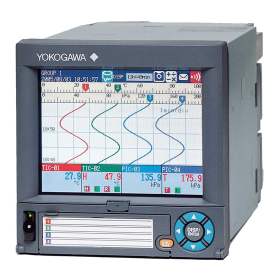
Basic Operation Panel Keys and Display Keys Key panel START STOP USER FUNC MENU DISP/ENTER key and four arrow keys (up, down, left, and right) Switches the operation screen. Selects and enters setup items. Soft keys Selects the menu that is displayed DISP/ENTER key at the bottom of the screen Up arrow key... - Page 15 Basic Operation Display Status display section Shows the display name, date/time, data recording, alarm icon, etc. Data display section Shows the measured data and the functional setup Display on the Status Display Section The following information is displayed in the status display section. Memory sample status Data type DISP: Display data...
-
Page 16: Run Modes
Basic Operation Run Modes Mode Transition Diagram Power ON Operation mode Setting mode Basic setting mode End menu > DISP/ENTER key MENU key Setting menu Basic setting Operation display display menu display Hold the FUNC key for MENU key 3 seconds or ESC key DISP/ENTER DISP/ENTER... -
Page 17: Entering Values And Characters
Basic Operation Entering Values and Characters The character/number input window and DISP/ENTER key are used to set the date/time, set the display span of the input range, set the tag, set the message string, enter the password, etc. Character/number input window DISP/ENTER key and four arrow keys (up, down, left, and right) Cursor... -
Page 18: Changing The Date/Time
Basic Operation Changing the Date/Time In this example, we will change the date from the 1st to the 6th. After carrying out this step, reset the time to the correct date/time. Display the operation mode screen. Press MENU once to display the setting menu. Select Date/Time Press DISP/ENTER once to open the Time set window. -
Page 19: Operation Example In The Setting Mode: Changing The Input Range
Basic Operation Operation Example in the Setting Mode: Changing the Input Range Set the input range of channel 2 to thermocouple type T and 0.0 to 400.0°C. Type T Channel 2 thermocouple Display the operation mode screen. Press MENU once to display the setting menu. Press the down arrow key once to select Meas channel. - Page 20 Basic Operation Press the TC soft key once. The cursor moves to Range, and the changed item is displayed in yellow. Select TC Press the Next soft key. . Press the T soft key once. The cursor moves to Span_L. .
-
Page 21: Operation Example In The Basic Setting Mode: Changing The Scan Interval
Basic Operation Operation Example in the Basic Setting Mode: Changing the Scan Interval In this example, we will change the scan interval. Here, the scan interval on the DX1012 is changed to 2 s. The selectable scan intervals are different on the model, but the procedure is the same. - Page 22 Basic Operation Press the down arrow key once to move the cursor to Scan interval. Press the 2s soft key once. The cursor moves to A/D integrate, and the changed item is displayed in yellow. Cancel the setting: Press ESC before pressing DISP/ENTER. Press DISP/ENTER once.
-
Page 23: Inserting/Removing A Cf Card
Basic Operation Inserting/Removing a CF Card Inserting a CF Card Open the operation cover. CAUTION Forcing the CF card into the slot with the upside down may cause damage. CF card With the label “This side up” facing up Insert the CF card into the slot. Displays the CF card icon Close the operation cover. - Page 24 Basic Operation Press the CF card eject button. When you eject the CF card, the storage media icon disappears. Press the eject button in until it clicks. The eject button stops at depressed position. Pinch the left and right sides of the CF card and remove it.
-
Page 25: Saving The Setup Data
Basic Operation Saving the Setup Data In this example, we will save the setup data to a file named “SF2” on the CF card. Display the operation mode screen. Press MENU once to display the setting menu. Press the up arrow key twice to select Save/Load. Press the right arrow key once and down arrow key three times. -
Page 26: Loading The Setup Data
Basic Operation Loading the Setup Data In this example, we will load the setup data “SF2” from the CF card and update the DX settings. Here, only the setup data of the setting mode is loaded. To load the setup data of both the setting mode and basic setting mode, press MENU, hold down FUNC for 3 s, select Load settings, Initialize >... -
Page 27: Setting The Input Range And Alarm
Setting the Input Range and Alarm Setup Example 1: Temperature Measurement Channel Type T Channel 1 thermocouple 0.0 to 200.0°C Setup Item Description Number in the Figure Channel Use channel 1. TI-001 Sensor Type T thermocouple Input range 0.0 to 200.0°C (1) Input Range Press MENU (switch to the setting mode) From the setting menu, select: Meas Channel >... -
Page 28: Setup Example 2: Flow Rate Measurement Channel And Alarm
Setting the Input Range and Alarm Setup Example 2: Flow Rate Measurement Channel and Alarm Flowmeter Channel 2 4 - 20 mA Convert to 1-5 V with a shunt resistor Setup Item Description Number in the Figure Channel Use channel 2. FI-002 Input signal 1-5V... -
Page 29: Setting The Display
Setting the Display Setup Example 3: Assigning Channels to Groups In this example, we will assign channels 1 and 2 to group 1. Group 1 Channel 1 Channel 2 Setup Item Description Number in the Figure Group Assign channel 1 and 2 to group 1. (1) Group MENU key (switch to the setting mode) and select Group set, Trip line Operation complete. -
Page 30: Setup Example 4: Setting The Time Scale
Setting the Display Setup Example 4: Setting the Time Scale Set the time per division of the trend waveform to 2 minutes. The sampling interval (the time corresponding to 1 dot) is 4 s when the trend interval is 2 min. 30 dots ×... -
Page 31: Setting The Data Storage
Setting the Data Storage Setup Example 5: Continuously Record Measured Data and Automatically Save In this example, we will continuously record and save the measured data of channel 1 and 2. For the procedure to set the channel, see “Setting the Input Range and Alarm” on page 26. For the procedure to set groups, see “Setting the Display”... - Page 32 Setting the Data Storage (3) Save the Settings Press ESC to return to the basic setting menu. Select End and press DISP/ENTER. The window appears for you to confirm the saving of the settings. Select Yes and press DISP/ENTER. The DX returns to the operation mode screen. (4) Channels to Be Recorded Press MENU (switch to the setting mode) From the setting menu, select: Meas Channel >...
-
Page 33: Setup Example 6: Saving Measured Data At The Specified Time
Setting the Data Storage Setup Example 6: Saving Measured Data at the Specified Time Using the settings of Setup Example 5, we will save the measured data once at hour 0 every day. Every hour 0 Automatically save to the CF card All settings other than those listed below are the same as Setup Example 5. -
Page 34: Customizing The Operation
Customizing the Operation Setup Example 7: Assigning the Screen Image Data Storage Function to the USER Key In this example, we will set the DX so that the displayed screen image data can be saved to the CF card by pressing the USER key. This function is called snapshot . The extension of snapshot data files is .png. -
Page 35: Setup Example 8: Registering Frequently Used Screens To The Favorite Key
Customizing the Operation Setup Example 8: Registering Frequently Used Screens to the Favorite Key Up to eight operation mode screens that are frequently used can be registered to the Favorite key. This enables you to monitor the operation by using only the Favorite key. This feature is convenient when comparing data such as historical trends. - Page 36 Customizing the Operation Press the favorite number (1 to 8) soft key. Press the Regist soft key. Show the window for entering the display name Enter the screen name. Select the digit: Left and right arrow soft keys Enter characters: Arrow keys and DISP/ENTER Delete a character: Use the arrow keys to select Del and press DISP/ENTER, or press the Bs soft key.
-
Page 37: Operation
Operation Starting the Memory Sample Press START once. Memory sample starts. Memory sample progress DISP: Display data Recording data EVENT: Event data START STOP USER FUNC MENU START key Operation complete. Stopping the Memory Sample Press STOP once. Display the confirmation window Select Mem+Math or Memory using the left and right arrow keys. -
Page 38: Switching The Trend Display, Digital Display, And Bar Graph Display
Operation Switching the Trend Display, Digital Display, and Bar Graph Display Press DISP/ENTER once to show the display selection menu. Left arrow key Up arrow key Right arrow key DISP/ENTER key Down arrow key Press the down arrow key to select TREND, DIGITAL, or BAR. Press the right arrow key once to display the sub menu. -
Page 39: Writing The Message "Start
Operation Writing the Message “START” Registering the Word “START” in Message Number 1 Press MENU (switch to the setting mode) and select Message. Press the 1-10 soft key. Press the Input soft key. Show the message registration window Select the digit: Left and right arrow soft keys Enter characters: Arrow keys and DISP/ENTER... - Page 40 Operation Writing Message Number 1 “START” This operation can be carried out while memory sample is in progress. The message is displayed on the trend display. Show the trend display first. Press FUNC (display the FUNC key menu), press the Message soft key, and press the 1-10 soft key.
-
Page 41: Connecting To An Ethernet Network
Connecting to an Ethernet Network Setup Example 9: Monitoring the DX on a PC Browser In this example, we will connect the PC and the DX via hub in a one-to-one relationship and display and monitor the DX screen on a browser on the PC. Ethernet Setup Item Description... - Page 42 Connecting to an Ethernet Network (2) Enabling the Web Server Function on the DX From the basic setting menu, select: Communication (Ethernet) > Server (3) Display the DX Screen on the PC From the basic setting menu, select: Communication (Ethernet) > Web page (4) Save the Settings Press ESC to return to the basic setting menu.
- Page 43 Connecting to an Ethernet Network (6) Checking the Connection Send the command below from the PC and check that a correct response is returned. Send >ping 192.168.1.101 Response example >Reply from 192.168.1.101: bytes=32 time<10ms TTL=255 (7) Displaying the DX Screen on the Browser Start the browser on the PC.
-
Page 44: Setup Example 10: Automatically Transferring The Measured Data File To An Ftp Server
Connecting to an Ethernet Network Setup Example 10: Automatically Transferring the Measured Data File to an FTP Server In this example, we will configure the DX so that the measured data is automatically transferred to an FTP server on the network when the measured data is automatically saved to the CF card. - Page 45 Connecting to an Ethernet Network (3) Data to Be Transferred to the FTP Server From the basic setting menu, select: Communication (Ethernet) > FTP client > FTP transfer file (4) Connected setting FTP Server From the basic setting menu, select: Communication (Ethernet) > FTP client > FTP connection (5) Save the Settings Press ESC to return to the basic setting menu.
-
Page 46: Using Daqstandard
Using DAQSTANDARD Displaying the Measured Data on DAQSTANDARD In this example, we will display the measured data using the accompanying software program, DAQSTANDARD. Insert the CF card containing the measured data file (.DAD or .DAE extension) into the PC that has DAQSTANDARD installed. Start DAQSTANDARD. -
Page 47: Installation And Wiring
Installation and Wiring Installation Location Install the DX indoors in a location that meets the following conditions. • Instrumentation Panel The DX is designed to be installed in an instrumentation panel except for the desktop type. • Well-Ventilated Location To prevent overheating, install the DX in a well-ventilated location. For the panel cut dimensions when arranging multiple DXs, see the page 48. -
Page 48: Installation Procedure
Installation and Wiring Installation Procedure Installation Procedure (Panel Mount Type) Use a steel panel of thickness 2 mm to 26 mm. Insert DX from the front of the panel. Mount the DX to the panel using the mounting brackets that come with the package as shown in the figure below. - Page 49 Installation and Wiring External Dimensions and Panel Cut Dimensions Unit: mm (approx. inch) Unless otherwise specified, tolerance is ±3% (however, tolerance is ±0.3 mm when below 10 mm). Panel mount type DX1000 DX1000N 228.5 (9.0) 258.5 (10.18) 224.1 (8.82) 254.1 (10.0) 170.5 (6.71) 200.5 (7.89) 40.9 (1.61)
-
Page 50: Input Signal Wiring
Installation and Wiring Input Signal Wiring WARNING • To prevent electric shock while wiring, ensure that the power supply source is turned OFF. CAUTION • If a strong tension is applied to the cable wired to the DX, the terminals of the DX and/or the cable can be damaged. - Page 51 Installation and Wiring Wiring Procedure A terminal cover is screwed in place on the measuring input terminal block on the rear panel. A label indicating the terminal arrangement is affixed to the cover. Turn OFF the DX and remove the terminal cover. Connect the signal wires to the terminals.
- Page 52 Installation and Wiring Wiring Screw Terminals DC voltage input/DI (ON/OFF) input TC input Compensating leadwire DC voltage input – – – RTD input DC current input DC current input – – Shunt resistor Example: For 4 to 20 mA input, use a shunt resistor of 250 Ω...
-
Page 53: Optional Terminal Wiring
Installation and Wiring Optional Terminal Wiring WARNING • To prevent electric shock while wiring, ensure that the power supply source is turned OFF. • If a voltage of more than 30 VAC or 60 VDC is to be applied to the output terminals, use ring-tongue crimp-on lugs with insulation sleeves on all terminals to prevent the wires from slipping out when the screws become loose. - Page 54 Installation and Wiring Arrangement of the Optional Terminals Optional terminal block Terminal arrangement of /A1 to /A3, /R1, /F1, and /PM1 options /PM1 Pulse input terminal Status output FAIL output Remote control input terminal Terminal arrangement of /TPS2 and /TPS4 options −...
-
Page 55: Alarm Output Terminal, Fail Output Terminal, And Status Output Terminal (/A1, /A2, /A3, And /F1)
Installation and Wiring Alarm Output Terminal, FAIL Output Terminal, and Status Output Terminal (/A1, /A2, /A3, and /F1) Output format: Relay contact Contact rating: 250 VAC (50/60 Hz)/3 A, 250 VDC/0.1 A (for resistor load) Withstand voltage: 1600 VAC at 50/60 Hz for one minute (between output terminals and the ground terminal) Remote Control Input Terminal (/R1) •... -
Page 56: Connecting To The Rs-422A/485 (/C3)
Installation and Wiring Connecting to the RS-422A/485 (/C3) Four-wire system Two-wire system FG (Frame Ground) Frame ground of the DX. SG (Signal Ground) Signal ground. SDB (Send Data B) Send data B (+). SDA (Send Data A) Send data A (−). RDB (Received Data B) Receive data B (+). -
Page 57: Power Supply Wiring
Installation and Wiring Power Supply Wiring Panel Mount Type Precautions to Be Taken While Wiring the Power Supply This section explains the precautions to be taken on models whose rated supply voltage is 100 to 240 VAC. Make sure to follow the warnings below when wiring the power supply. To prevent electric shock and damage to the DX, observe the following warnings. - Page 58 OFF. • To prevent electric shock or fire, be sure to use the power cord supplied by YOKOGAWA. • Make sure to perform protective earth grounding to prevent electric shock. Connect the power cord of the desktop type to a three-prong power outlet with a protective earth terminal.
-
Page 59: Recommended Replacement Periods For Worn Parts
For the actual replacement period, consider the actual conditions of use. Replacement of parts will be carried out by a YOKOGAWA engineer or an engineer certified by YOKOGAWA. Contact your nearest YOKOGAWA dealer when such replacement is necessary. -
Page 60: Setup Items And Default Values
Setup Items and Default Values The setup items and the default values in the setting mode are listed below. Enter the settings that you are using in the Setting column for your convenience. Setting mode menu Page 60 Page 60 to 62 Page 63 and 64* Page 65 Page 65... -
Page 61: Setup Items In Setting Mode And Their Default Values
Setup Items and Default Values Setup Items in Setting Mode and Their Default Values Date/Time > Date&Time Setup Item Selectable Range or Selections Default Value Setting Date&Time > Time set Date/Time > Daylight Saving Time Setup Item Selectable Range or Selections Default Value Setting Use/Not... - Page 62 Setup Items and Default Values Setup Item Selectable Range or Selections Default Value Setting Mode=1-5V Range 1-5V 1-5V Span Lower 0.800 to 5.200 1.000 Span Upper 0.800 to 5.200 5.000 Scale Lower –30000 to 30000, decimal position :0 to 4 0.00 Scale Upper –30000 to 30000, decimal position :0 to 4...
- Page 63 Setup Items and Default Values Meas channel > Bar graph Setup Item Selectable Range or Selections Default Value Setting First-CH, Last-CH 1/2/3/.../11/12 (Depends on the model.) Base position Normal/Center Normal Division 4/5/6/7/8/9/10/11/12 Meas channel > Partial Setup Item Selectable Range or Selections Default Value Setting First-CH, Last-CH...
- Page 64 Setup Items and Default Values Math channel > Expression, Alarm Setup Item Selectable Range or Selections Default Value Setting First-CH, Last-CH 101/102/.../124 (Depends on the model.) Math On/Off Math > Calculation expression 120 characters or less – Math > Span Lower –9999999 to 99999999, decimal position: 0 to 4 –...
- Page 65 Setup Items and Default Values Math channel > Partial Setup Item Selectable Range or Selections Default Value Setting First-CH, Last-CH 101/102/.../124 (Depends on the model.) On/Off On/Off Expand 1 to 99% Boundary Span Lower+1digit to Span Upper–1digit 0.00 Math channel > Alarm mark Setup Item Selectable Range or Selections Default Value...
- Page 66 Setup Items and Default Values Display > Trend /Save interval Setup Item Selectable Range or Selections Default Value Setting Trend interval [/div] 15s/30s/1min/2min/5min/10min/15min/20min/ 1min 30min/1h/2h/4h/10h (Depends on the model.) Save interval 10min to 31day (Depends on the trend interval.) 1h Second interval [/div] 15s/30s/1min/2min/5min/10min/15min/20min/ 1min...
- Page 67 Setup Items and Default Values Timer, Event action > Timer Setup Item Selectable Range or Selections Default Value Setting Timer No. 1/2/3/4 Mode Off/Relative/Absolute Relative > Interval 00:01 to 24:00 01:00 Relative > Reset at Math Start On/Off Absolute > Interval 1min/2min/3min/4min/5min/6min/10min/ 12min/15min/20min/30min/1h/2h/3h/4h/ 6h/8h/12h/24h...
- Page 68 Setup Items and Default Values Data save > File header, File name Setup Item Selectable Range or Selections Default Value Setting File header > Characters 50 characters or less – Data file name > Structure Date/Serial/Batch Date Data file name > Identified strings 16 characters or less –...
-
Page 69: Setup Items In Basic Setting Mode And Their Default Values
Setup Items and Default Values Setup Items in Basic Setting Mode and Their Default Values Alarm Setup Item Selectable Range or Selections Default Value Setting Basic settings Reflash On/Off Rate of change > Decrease 1 to 32 Rate of change > Increase 1 to 32 Indicator Hold/Nonhold... - Page 70 Setup Items and Default Values Environment > Security, Media save Setup Item Selectable Range or Selections Default Value Setting Security > Key Off/Login/Keylock Security > Communication Off/Login Save > Auto save On/Off Environment > Batch Setup Item Selectable Range or Selections Default Value Setting On/Off...
- Page 71 Setup Items and Default Values Login > Basic settings, Admin settings, User settings Setup Item Selectable Range or Selections Default Value Setting User basic settings > Auto logout Off/1min/2min/5min/10min User basic settings > Operation without Login Off/Display Admin settings > Admin number 1/2/3/4/5 Admin settings >...
- Page 72 Setup Items and Default Values Communication (Ethernet) > IP-address Setup Item Selectable Range or Selections Default Value Setting DHCP Use/Not DNS accession Use/Not Host-name register Use/Not Fixed IP-address > IP-address 0.0.0.0 to 255.255.255.255 0.0.0.0 Fixed IP-address > Subnet mask 0.0.0.0 to 255.255.255.255 0.0.0.0 Fixed IP-address >...
- Page 73 Setup Items and Default Values Communication (Ethernet) > E-Mail Setup Item Selectable Range or Selections Default Value Setting Basic settings SMTP server name 64 characters or less – Port number 0 to 65535 Recipient 1 150 characters or less – Recipient 2 150 characters or less –...
- Page 74 Setup Items and Default Values Communication (Ethernet) > FTP client Setup Item Selectable Range or Selections Default Value Setting FTP transfer file Disp&Event data On/Off Report On/Off Snapshot On/Off FTP connection Primary/Secondary Primary Server name 64 characters or less – Port number 0 to 65535 Login name...
- Page 75 Setup Items and dDefault Values Communication (Serial) Setup Item Selectable Range or Selections Default Value Setting Basic settings Baud rate 1200/2400/4800/9600/19200/38400 9600 Data length Parity Odd/Even/None Even Handshaking Off:Off/XON:XON/XON:RS/CS:RS Off:Off Address 1 to 99 Protocol Normal/Modbus/Modbus-M Normal Modbus master > Basic settings Read cycle 125ms/250ms/500ms/1s/2s/5s/10s Timeout...