Table of Contents
Advertisement
Advertisement
Table of Contents

Related Manuals for Motorola XPR 3000 Series


Summary of Contents for Motorola XPR 3000 Series
- Page 1 3000 Series Quick Reference Guide and Safety Manual...
- Page 3 Regulatory Compliance and Product Safety for Portable Two-Way Radios BEFORE USING THIS RADIO, READ THIS BOOKLET WHICH CONTAINS IMPORTANT OPERATING INSTRUCTIONS FOR SAFE USAGE C a u t i o n AND RF ENERGY AWARENESS AND CONTROL INFORMATION AND OPERATIONAL INSTRUCTIONS FOR COMPLIANCE WITH RF ENERGY EXPOSURE LIMITS IN APPLICABLE NATIONAL AND INTERNATIONAL...
-
Page 4: Rf Energy Exposure Awareness And Control Information And Operational Instructions For Occupational Use
RF exposure for both workers and the general public. These recommended RF exposure levels include substantial margins of protection. All Motorola two-way radios are designed, manufactured, and tested to ensure they meet government-established RF exposure levels. In addition, manufacturers also recommend specific... - Page 5 Exposure awareness can be facilitated by the use of a product label directing users to specific user awareness information. Your Motorola two-way radio has a RF Exposure Product Label. Also, your Motorola user manual, or separate safety booklet includes information and operating instructions required to control your RF exposure and to satisfy compliance requirements.
- Page 6 FCC occupational exposure limits and may operate at duty factors of up to 50% talk. Your Motorola two-way radio complies with the following RF energy exposure standards and guidelines: • United States Federal Communications Commission (FCC), Code of Federal Regulations;...
- Page 7 RF Exposure Compliance and Control Guidelines and Operating Instructions To control your exposure and ensure compliance with the occupational/controlled environment exposure limits, always adhere to the following procedures. Guidelines: • DO NOT remove the RF Exposure Label from the device. •...
- Page 8 Use of non-Motorola-approved antennas, batteries, and accessories may exceed the FCC (IEEE) and ICNIRP RF exposure guidelines. • For a list of Motorola-approved accessories, visit the following website, which lists approved accessories for your radio model: www.motorolasolutions.governmentandenterprise...
- Page 9 Electromagnetic Interference/ Compatibility Nearly every electronic device is susceptible NOTE: to electromagnetic interference (EMI) if inadequately shielded, designed, or otherwise configured for electromagnetic compatibility. Facilities To avoid electromagnetic interference and/or compatibility conflicts, turn off your radio in any facility where posted notices instruct you to do so. Hospitals or health care facilities may be using equipment that is sensitive to external RF energy.
- Page 10 • Use the ear opposite the pacemaker to minimize the potential for interference. • Turn the radio OFF immediately if there is any reason to suspect that interference is taking place. Hearing Aids Some digital wireless radios may interfere with some hearing aids.
-
Page 11: Operational Warnings
To protect your hearing: • Use the lowest volume necessary to do your job. • Turn up the volume only if you are in noisy surroundings. • Turn down the volume before adding headset or earpiece. • Limit the amount of time you use headsets or earpieces at high volume. - Page 12 Potentially Explosive Atmospheres (Explosive atmospheres refers to hazard classified locations that may W A R N I N G contain hazardous gas, vapors, or dusts.) Turn off your radio prior to entering any area with a potentially explosive atmosphere unless it is a portable radio type especially qualified for use in such areas as Intrinsically Safe (for example, Factory Mutual, CSA,...
-
Page 13: Operational Cautions
Blasting Caps and Blasting Areas To avoid possible interference with blasting operations, turn off your radio W A R N I N G when you are near electrical blasting caps, in a blasting area, or in areas posted: "Turn off two-way radio." Obey all signs and instructions. - Page 14 Intrinsically Safe Radio Information The Intrinsically safe approval unit refers to a product that has been approved as intrinsically safe by an approval agency (for example FM Approvals, CSA, UL, or Cenelec) and certifies that a particular product meets the Agency's applicable intrinsic safety standards for specific types of hazardous classified locations.
- Page 15 Warnings for Radios Approved as Intrinsically Safe Radios must ship from the Motorola manufacturing facility with the hazardous atmosphere capability and the intrinsic safety approval labelling (FM, UL, CSA, CENELEC). Radios will not be upgraded to this capability and labeled once they have been shipped to the field.
- Page 16 • DO NOT replace or change accessories in a hazardous atmosphere. Contact sparking may occur while installing or removing W A R N I N G accessories and cause an explosion or fire. • Turn the radio off before removing or installing a battery or accessory.
- Page 17 APPROVAL ARE THE W A R N I N G RESPONSIBILITY OF THE USER. Repairs to a Motorola FM approved radio product should only be done at a location that has been FM audited under the FM 3605 repairs and service standard.
- Page 18 Approval Label identifies the approved Accessories and or options that can be used with that portable radio unit. Using a non-Motorola-intrinsically-safe battery and or accessory with the Motorola approved radio unit will void the intrinsically safe approval of that radio unit. English...
-
Page 19: Radio Controls
XPR 3000 Series Digital Portable Radios Quick Reference Card Radio Controls Limited Keypad Radio Refer to User Guide for more details on your NOTE: radio's operations/features Record your radio’s programmable button functions in the blanks provided. SP represents short press, LP represents long press. - Page 20 Non-Keypad Radio Channel Selector Knob On/Off/Volume Control Knob LED Indicator Push-to-Talk (PTT) Button Microphone Side Button 1 (Programmable) SP: ____________LP: ___________ English...
- Page 21 Side Button 2(Programmable) SP: ___________ LP: ___________ Left Navigation Button Menu Button Front Button P1 (Programmable) SP: ___________ LP: ___________ OK Button Front Button P2 (Programmable) SP: ___________ LP: ___________ Back/Home Button Right Navigation Button Display Speaker Universal Connector for Accessories Antenna English...
-
Page 22: Display Icons
Display Icons The following are the icons that appear on the radio’s display. Received Signal Strength Indicator (RSSI) The number of bars displayed represents the radio signal strength. Four bars indi- cate the strongest signal. This icon is only displayed while receiving. Battery The number of bars (0 –... - Page 23 Scan – Priority 1* Radio detects activity on channel/group designated as Priority 1. Scan – Priority 2 * Radio detects activity on channel/group designated as Priority 2. Vote Scan Vote scan feature is enabled. Monitor Selected channel is being monitored. Talkaround* In the absence of a repeater, radio is cur- rently configured for direct radio to radio...
-
Page 24: Call Icons
Tones Disable Tones are turned off. Power Level Radio is set at Low power. Radio is set at High power. Call Icons The following icons appear during a call, and in the Contacts list to indicate ID type. Private Call Indicates a Private Call in progress. - Page 25 Sent Items Icons The following icons appear at the top right corner of the radio’s display in the Sent Items folder. Sent Successfully The text message is sent successfully. Send Failed The text message cannot be sent. In-Progress •The text message to a subscriber alias or ID is pending transmission, followed by waiting for acknowledgement.
-
Page 26: Led Indicator
LED Indicator Radio is transmitting at low battery Blinking red – condition, receiving an emergency transmission or has failed the self-test upon powering up. Radio is powering up, or transmitting. Solid green – Also indicates full charge of the battery when Battery Strength button is pressed. -
Page 27: Charging The Battery
Your radio is powered by a Nickel Metal-Hydride (NiMH) or Lithium-Ion (Li-lon) battery. To avoid damage and comply with warranty terms, charge the battery using a Motorola charger exactly as described in the charger user guide. Charge a new battery 14 to 16 hours before initial use for best performance. -
Page 28: Attaching The Battery
Attaching the Battery Align the battery with the rails on the back of the radio. Press the battery firmly, and slide upward until the latch snaps into place. Slide battery latch into lock position. To remove the battery, turn the radio off. Move the battery latch into unlock position and hold, and slide the battery down and off the rails. -
Page 29: Attaching The Antenna
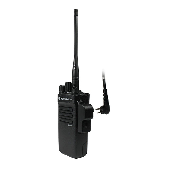
Attaching the Antenna With the radio turned off, set the antenna in its receptacle and turn clockwise. Make sure that the antenna is tightened securely to the radio. To remove the antenna, turn the antenna counterclockwise. English... -
Page 30: Attaching The Belt Clip
Attaching the Belt Clip Align the grooves on the clip with those on the battery and press downward until you hear a click. To remove the clip, press the belt clip tab away from the battery. Using a key may be helpful. - Page 31 Attaching the Universal Connector Cover (Dust Cover) The universal connector is located on the antenna side of the radio. It is used to connect MOTOTRBO accessories to the radio. Insert the hooked end of the cover into the slots above the universal connector.
-
Page 32: Powering Up The Radio
Powering Up the Radio Rotate the On/Off/Volume Control Knob clockwise until you hear a click. You see MOTOTRBO (TM) on the radio’s display momentarily, followed by a welcome message or welcome image. The LED lights up solid green and the Home screen lights up if the backlight setting is set to turn on automatically. -
Page 33: Accessing The Radio From Password
Accessing the Radio from Password Limited Keypad Radio 1. Power up the radio. 2. You will be prompt to enter a four-digit password. 3. Enter your current four-digit password. Press < or > to choose each digit’s numeric value (0-9). Press >... -
Page 34: Selecting A Zone
Non-Keypad Radio 1. Power up the radio. 2. You hear a continuous tone. 3. Use the Channel Selector Knob to enter the first digit of the password. 4. Press Side Button 1 or 2 to enter each digit of the remaining three digits of the password. - Page 35 A zone is a group of channels. The limited keypad radio supports up to 50 channels and 128 zones, with a maximum of 16 channels per zone. Use the following procedure to select a zone. Procedure: Press the programmed Zone button and proceed to Step 3.
-
Page 36: Selecting A Radio Channel, Subscriber Id, Or Group Id
Selecting a Radio Channel, Subscriber ID, or Group ID Once the required zone is displayed (if you have mul- tiple zones in your radio), turn the programmed Chan- nel Selector Knob to select the channel. Making a Group Call 1. Turn the Channel Selector Knob to select the channel with the active group alias or ID. -
Page 37: Making A Private Call
channel is free for you to respond. Press the PTT button to respond. If there is no voice activity for a predetermined period of time, the call ends. 7. Radio returns to the screen you were on prior to initiating the call. Making a Private Call 1. -
Page 38: Making An All Call
If there is no voice activity for a predetermined period of time, the call ends. 7. You hear a short tone. 8. The display shows Call Ended.** NOTE: Indicates a conventional Digital Mode- Only feature. **not applicable for Non-Keypad Radio. Making an All Call 1. -
Page 39: Scanning Channels
Scanning Channels NOTE: This feature is not applicable in Capacity Plus. Press the programmed Scan button to turn scan on or off. During scan, the LED blinks yellow and the scan icon is displayed Making a Call Alert Limited Keypad Radio Press the programmed One Touch Access button and proceed to Step 5. -
Page 40: Sending A Quick Text Message
1. If the Call Alert acknowledgement is received, the display shows positive mini notice. If the Call Alert acknowledgement is not received, the display shows negative mini notice. Non-Keypad Radio 1. Press the programmed One Touch Access but- ton to make a Call Alert to the predefined ID. 2. - Page 41 4. < or > to the required Quick Text and press e to select. 5. < or > to the required alias or ID and press e to select. The display shows transitional mini notice, con- firming your message is being sent. 6.
-
Page 42: Sending An Emergency Alarm
Sending an Emergency Alarm NOTE: If your radio is set to Silent, it will not display any audio or visual indicators during Emergency mode. 1. Press the programmed Emergency On button. 2. The display shows Tx Alarm and the destination alias. - Page 43 English...
- Page 44 MOTOROLA, MOTO, MOTOROLA SOLUTIONS and the Stylized M logo are trademarks or registered trademarks of Motorola Trademark Holdings, LLC and are used under license. All other trademarks are the property of their respective owners. © 2011 Motorola Solutions, Inc. All rights reserved.