GE MDS Mercury Series Reference Manual
Wireless ip/ethernet transceiver
Hide thumbs
Also See for MDS Mercury Series:
- Setup manual (4 pages) ,
- Setup manual (4 pages) ,
- Reference manual (196 pages)
Table of Contents
Advertisement
Quick Links
Download this manual
See also:
Reference Manual
Advertisement
Table of Contents

Related Manuals for GE MDS Mercury Series


Summary of Contents for GE MDS Mercury Series
- Page 1 MDS Mercury Series Wireless IP/Ethernet Transceiver Covering all AP and Remote Units including Mercury 900, 3650, and Option Set 1 Remotes 05-4446A01, Rev. D DECEMBER 2008...
-
Page 3: Table Of Contents
1.2 PRODUCT DESCRIPTION..................... 4 1.2.1 Model Offerings ........................6 1.2.2 Remote Radio with Option Set 1 ..................7 1.2.3 GE MDS P23 Protected Network (Redundant) Configuration ..........8 1.2.4 External GPS PPS Option ....................9 1.3 APPLICATIONS ......................9 1.3.1 Mobile/Fixed Data System ....................9 1.3.2 Wireless LAN ........................ - Page 4 2.4 STEP 3 — CONNECT PC TO THE TRANSCEIVER............25 2.5 STEP 4 — REVIEW TRANSCEIVER CONFIGURATION 2.5.1 Getting Started 2.5.2 Procedure 2.5.3 Basic Configuration Defaults 2.6 STEP 5 — CONNECT LAN OR SERIAL DATA EQUIPMENT 2.6.1 Option 1 Set (MaxRM) Connectors 2.7 STEP 6 —...
- Page 5 3.7.2 Wireless Security Menu ..................... 94 3.7.3 IEEE 802.1x Device Authentication ................... 96 3.7.4 Manage Certificates ......................98 3.8 REDUNDANCY CONFIGURATION (AP ONLY) ............101 3.9 GPS CONFIGURATION (REMOTE ONLY) ..............106 3.10 DEVICE INFORMATION MENU ................108 3.11 PERFORMANCE INFORMATION MENU..............109 3.12 MAINTENANCE/TOOLS MENU ................
- Page 6 We also became experts in wireless communication standards and system applications worldwide. The result of our efforts is that today, thousands of utilities around the world rely on GE MDS-based wireless networks to manage their most critical assets.
- Page 7 As your wireless needs change you can continue to expect more from GE MDS. We'll always put the performance of your network above all. Visit us at www.GEmds.com...
- Page 8 A power connector with screw-type retaining screws as supplied by GE MDS must be used. Do not disconnect equipment unless power has been switched off or the area is known to be non-hazardous.
- Page 9 If you have additional questions or need an exact specification for a product, please contact our Customer Service Team using the information at the back of this guide. In addition, manual updates can often be found on the GE MDS Web site at www.GEmds.com.
- Page 10 viii Mercury Reference Manual 05-4446A01, Rev. D...
-
Page 11: Product Overview And Applications
1.2 PRODUCT DESCRIPTION ........... 4 1.2.1 Model Offerings ..............6 1.2.2 Remote Radio with Option Set 1 ..........7 1.2.3 GE MDS P23 Protected Network (Redundant) Config..8 1.2.4 External GPS PPS Option ............. 9 1.3 APPLICATIONS ..............9 1.3.1 Mobile/Fixed Data System ............. - Page 12 Mercury Reference Manual 05-4446A01, Rev. D...
-
Page 13: About This Manual
1.1 ABOUT THIS MANUAL This Reference Manual is one of two publications provided for users of the Mercury Series transceiver system. It contains detailed product information, an overview of common applications, a screen-by-screen review of the menu system, technical specifications, suggested settings for various scenarios, and troubleshooting information. -
Page 14: Product Description
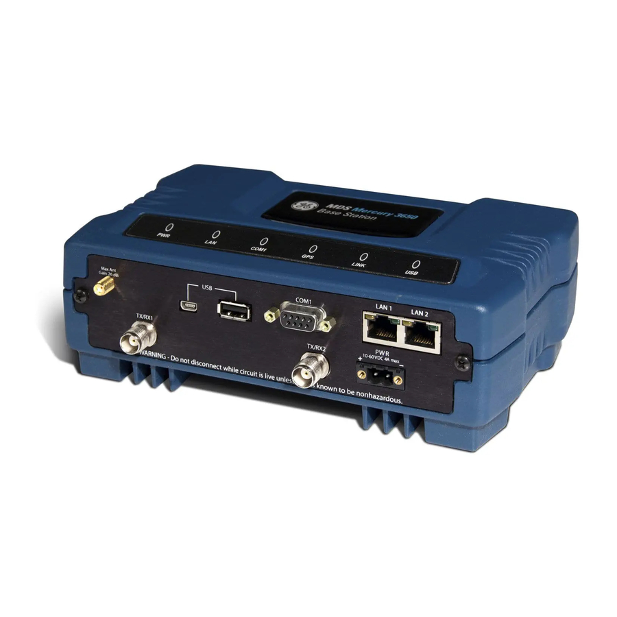
Mercury system the best combination of security, range, and speed of any industrial wireless solution on the market today. Invisible place holder Figure 1-1. The GE MDS Mercury Series Transceiver (Remote unit shown, AP similar in appearance) Rugged Packaging The transceivers are housed in a compact and rugged die cast-aluminum case that need only be protected from direct exposure to the weather. - Page 15 Security is not a one-step process that can simply be turned on and for- gotten. It must be practiced and enforced at multiple levels, 24 hours-a-day and 7 days-a-week. See “GE MDS CYBER SECURITY SUITE” on Page 17 for more information about the transceiver’s secu- rity tools.
-
Page 16: Model Offerings
• Built-in GPS Receiver—GPS technology is used for timing and location data. The only external equipment needed for this func- tionality is a GPS antenna available from GE MDS). 1.2.1 Model Offerings The transceiver comes in two primary models—Access Point and Remote. -
Page 17: Remote Radio With Option Set 1
FCC registration before operation can begin. Other restrictions may apply based on your location and “grandfathered” FSS users. Check local requirements before operation. GE MDS has pub- lished a whitepaper containing frequently asked questions about the 3.65–3.70 GHz band. -
Page 18: Ge Mds P23 Protected Network (Redundant) Configuration
The internal WiFi module has FCC modular approval and may only be operated by connecting one of the GE MDS approved antennas (see 802.11 WiFi Module Specifications below) to the reverse-SMA con- nector on the radio’s front panel. The WiFi module can operate as an 802.11 Access Point or Infrastructure Station, according to user config-... -
Page 19: External Gps Pps Option
protected chassis. For system-level information on this product, refer to MDS publication 05-4161A01. Invisible place holder Figure 1-3. MDS P23 Protected Network Station (incorporates two transceivers, with automatic switchover) 1.2.4 External GPS PPS Option The External GPS Precise Positioning Service (PPS) option allows for an external GPS device to provide the PPS input to the Mercury. -
Page 20: Wireless Lan
Invisible place holder Mercury Mercury AP remote Video Surveillance RTU/PLC (Ethernet) MDS NETview MS® Mercury Long Range WLAN remote RTU/PLC Computer Router RS-232 (Serial) MDS 4710 RTU/PLC RS-232 RS-232 (Serial) MDS 4790 Master Radio MDS 4710 Server (Ethernet) Licensed Serial/IP Integration Mercury Control Center Mercury... -
Page 21: Point-To-Point Lan Extension
IP format. A Remote transceiver with its serial port connected to a GE MDS serial-based radio, such as the MDS x790/x710, MDS TransNET and others, provides a path for bringing the data from the older radio into the IP/Ethernet environment of a Mercury-based system. -
Page 22: Wireless Lan With Mixed Services
to different SCADA hosts). A Mercury radio provides this capability using a single remote unit. The unit’s serial port can be connected via IP to different SCADA hosts, transporting different (or the same) proto- cols. Both data streams are completely independent, and the transceiver provides seamless simultaneous operation as shown in Figure 1-8. -
Page 23: Upgrading Older Wireless Network With Serial Interfaces
Millions of wireless data products have been installed in the last two decades for licensed and license-free operation, many of them manufac- tured by GE MDS. There are several ways that these systems can benefit from incorporating Mercury equipment. The chief advantages are inter- face flexibility (serial and Ethernet in one unit), and higher data throughput. -
Page 24: Network Design Considerations
NOTE: Several previous GE MDS-brand products had non-standard signal lines on their interface connectors (for example, to control sleep functions and alarm lines). These special func- tions are not provided nor supported by the Mercury trans- ceiver. Consult equipment manuals for complete pinout information. - Page 25 ration is sometimes required in a network that includes a distant Remote that would otherwise be unable to communicate directly with the Access Point station due to distance or terrain. The geographic location of a repeater station is especially important. Choose a site that allows good communication with both the Access Point and the outlying Remote site.
-
Page 26: Protected Network Operation Using Multiple Access Points
Section 5.1.2, Site Selection (beginning on Page 162). 1.4.2 Protected Network Operation using Multiple Although GE MDS transceivers have a very robust design and have undergone intensive testing before being shipped, it is possible for iso- lated failures to occur. In mission-critical applications, down time can... -
Page 27: Ge Mds Cyber Security Suite
(See “A Word About Radio Interference” on Page 168 for more details.) 1.5 GE MDS CYBER SECURITY SUITE Today, the operation and management of an enterprise is increasingly dependent on electronic information flow. An accompanying concern becomes the cyber security of the communication infrastructure and the security of the data itself. - Page 28 Table 1-2. Security Risk Management Security Vulnerability GE MDS Cyber Security Solution Unauthorized access to the backbone • IEEE 802.1x device authentication network through a foreign remote radio •...
-
Page 29: Accessories
The transceiver can be used with one or more of the accessories listed in Table 1-3. Contact the factory for ordering details. Table 1-3. Accessories Accessory Description GE MDS Part No. AC Power A small power supply module designed for 01-3682A02 Adapter Kit continuous service. - Page 30 Table 1-3. Accessories (Continued) Accessory Description GE MDS Part No. DIN Rail Bracket used to mount the transceiver to 03-4022A03 Mounting standard 35 mm DIN rails commonly found in Bracket equipment cabinets and panels. COM1 Interface DB-25(F) to DB-9(M) shielded cable assembly...
-
Page 31: Tabletop Evaluation & Test Setup
TABLETOP EVALUATION AND TEST SETUP 2 Chapter Counter Reset Paragraph Contents 2.1 OVERVIEW ................23 2.2 STEP 1—CONNECT THE ANTENNA PORTS...... 23 2.3 STEP 2—CONNECT THE PRIMARY POWER ..... 24 2.4 STEP 3—CONNECT PC TO THE TRANSCEIVER....25 2.5 STEP 4—REVIEW TRANSCEIVER CONFIGURATION ..25 2.5.1 Getting Started ............... - Page 32 Mercury Reference Manual 05-4446A01, Rev. D...
-
Page 33: Overview
2.1 OVERVIEW GE MDS recommends that you set up a “tabletop network” to verify the basic operation of the transceivers. This allows experimenting with net- work designs, configurations, or network equipment in a convenient location. This test can be performed with any number of radios. -
Page 34: Step 2-Connect The Primary Power
(RSSI) at each transceiver during the test. In no case should a signal greater than –50 dBm be applied to any transceiver in the test setup. GE MDS recom- mends an RF power output level of +20 dBm from the AP. -
Page 35: Step 3-Connect Pc To The Transceiver
2.4 STEP 3—CONNECT PC TO THE TRANSCEIVER Connect a PC’s Ethernet port to the port using an Ethernet cross- over cable. The LED should light. Alternatively, you can use a COM1 serial cable to connect to the port (Figure 2-3 on Page 27). -
Page 36: Step 5-Connect Lan Or Serial Data Equipment
Table 2-1. Basic Configuration Defaults Item Menu Location Default Values/Range Main Menu>> Network Name MDS-Mercury • 1–15 alphanumeric Radio Configuration>> characters Network Name • Case-sensitive; can be mixed case Main Menu>> IP Address 192.168.1.1 Contact your network Network Configuration>> administrator IP Address Main Menu>>... - Page 37 Invisible place holder LED INDICATOR LAN PORT PANEL COM1 SERIAL PORT RX2 ANTENNA PORT DC POWER INPUT GPS ANTENNA TX/RX1 (10—30 VDC, 2.5A) CONNECTION ANTENNA PORT Figure 2-3. Transceiver Interface Connectors (Standard unit shown; See Figure 2-4 on Page 28 for MaxRM unit) LED INDICATOR PANEL •...
-
Page 38: Option 1 Set (Maxrm) Connectors
2.6.1 Option 1 Set (MaxRM) Connectors Figure 2-4 shows the interface connectors on the front panel of the Option 1 Set (MaxRM) Remote transceiver. NOTE: The use of shielded Ethernet cable is recommended for connection to the radio’s port. The radio meets regulatory emission standards without shielded cable, but shielding reduces the possibility of interference in sensitive environ- ments, and is in keeping with good engineering practice. -
Page 39: Step 6-Check For Normal Operation
GPS ANTENNA PORT • — Coaxial connector (SMA-type) for connection of a GPS receiving antenna. Provides 3.5 Vdc output for compatibility with powered (active) GPS antennas. Do not short this connector, as you might cause damage to the internal power supply. The GPS receiving antenna’s gain must be 16 dBi or less. - Page 40 If the radio network seems to be operating properly based on observa- tion of the unit’s LEDs, use the command to verify the link integ- PING rity with the Access Point. Table 2-2. Transceiver LED Functions LED Label Activity Indication Primary power (DC) present Blinking Unit in “Alarmed”...
-
Page 41: Embedded Management System
DEVICE MANAGEMENT 3 Chapter Counter Reset Paragraph Contents 3.1 MS INTRODUCTION............. 33 3.1.1 Differences in the User Interfaces .......... 33 3.2 ACCESSING THE MENU SYSTEM ........35 3.2.1 Methods of Control ..............36 3.2.2 PC Connection and Log In Procedures ......... 36 3.2.3 Navigating the Menus ............ - Page 42 3.10 DEVICE INFORMATION MENU.......... 108 3.11 PERFORMANCE INFORMATION MENU ......109 3.12 MAINTENANCE/TOOLS MENU.......... 122 3.12.1 Installing Firmware via TFTP ..........128 3.12.2 Auto Firmware Upgrade Menu (AP Only) ......137 3.13 PERFORMANCE OPTIMIZATION ........139 3.13.1 Proper Operation What to Look For ........142 Mercury Reference Manual 05-4446A01, Rev.
-
Page 43: Ms Introduction
Ethernet-based interfaces. Essentially, the same capabilities are avail- able through any of these paths. For support of SNMP software, a set of MIB files is available for down- load from the GE MDS Web site at www.GEmds.com . An overview of SNMP commands can be found at SNMP Agent Configuration section... - Page 44 Figure 3-1. Embedded Management System Top-Level Flowchart Mercury Reference Manual 05-4446A01, Rev. D...
-
Page 45: Accessing The Menu System
Figure 3-2. View of MS with a text-based program (Console Terminal shown Telnet has similar appearance) Invisible place holder Figure 3-3. View of the MS with a Browser (Selections at left provide links to the various menus) 3.2 ACCESSING THE MENU SYSTEM The radio has no external controls or adjustments. -
Page 46: Methods Of Control
3.2.1 Methods of Control Access the unit’s configuration menus in one of several ways: • Local Console—This is the primary method used for the exam- COM1 ples in this manual. Connect a PC directly to the port using a serial communications cable and launch a terminal com- munications program such as HyperTerminal (found on most PCs by selecting Start>>Programs>>Accessories>>Communica-... - Page 47 Invisible place holder Transceiver Transceiver To COM1 or LAN Port (See Text) T o COM1 or LAN Port (see text) PC Running T erminal Session PC Running Terminal Session (115,200 bps, 8N1) (115,200 bps, 8N1) Figure 3-4. PC Configuration Setup Starting a Local 1.
- Page 48 5. Enter your password (default password is admin ). For security, your password keystrokes do not appear on the screen. Press ENTER NOTE: Passwords are case sensitive. Do not use punctuation mark characters. You may use up to 13 alpha-numeric characters. The unit responds with the Starting Information Screen (Figure 3-6).
- Page 49 TIP: You can start a Telnet session on most PCs by selecting: Start>>Pro- . At the command prompt grams>>Accessories>>Command Prompt window, type the word telnet , followed by the unit’s IP address (e.g., ). Press to receive the Telnet log in telnet 10.1.1.168 ENTER screen.
-
Page 50: Navigating The Menus
Invisible place holder Figure 3-7. Log-in Screen when using a Web Browser NOTE: Passwords are case sensitive. Do not use punctuation mark characters. You may use up to 13 alpha-numeric characters. 5. Click . The unit responds with a startup menu screen similar to that shown in Figure 3-8. - Page 51 associated screen where settings may be viewed or changed. In most cases, pressing the ESCAPE key moves the screen back one level in the menu tree. In general, the top portion of menu screens show read-only information (with no user selection letter). The bottom portion of the screen contains parameters you can select for further information, alteration of values, or to navigate to other submenus.
-
Page 52: Basic Overview Of Operation
NOTE: In the menu descriptions that follow, parameter options/range, and any default values are displayed at the end of the text between square brackets. Note that the default setting is always shown after a semicolon: available settings or range; default setting 3.3 BASIC OVERVIEW OF OPERATION 3.3.1 Starting Information Screen Once you have logged into the Management System, the Starting Infor-... -
Page 53: Main Menu
• Alarmed —The unit has detected one or more alarms that have not been cleared. At Remote: • Scanning —The unit is looking for an Access Point beacon signal. • Ranging —Unit is adjusting power, timing, and frequency with an AP. •... - Page 54 Figure 3-10. Main Menu (AP) (AP menu shown, Remote similar; Differences noted in text below) Figure 3-11. Main Menu (MDS 3650 Remote Only) • Starting Information Screen —Select this item to return to the Start- ing Information screen described above. •...
-
Page 55: Configuring Network Parameters
• Security Configuration —Tools to configure the security services available with the transceiver’s environment. (See “SECURITY CONFIGURATION MENU” on Page • Redundancy Configuration —(AP Only) Allows setting of the cri- teria for switchover in the event of loss of associated Remotes or excessive packet receive errors. - Page 56 Figure 3-13. Network Configuration Menu (MaxRM radio) • Network Interface Config —Presents a menu where you can view or set various parameters (VLAN Status, IP Configuration, and DHCP Server Configuration). • Ethernet Port Config —Presents a menu for defining the status of the Ethernet port (enabled or disabled), port follows association, and Ethernet filtering configuration.
- Page 57 ceeds. The transceivers use UTC (Universal Time Coordinated) with a configurable time offset. [ NOTE: The Mercury gets time of day data from the GPS receiver if the receiver gets a satellite fix. Network Interface Configuration Submenu Invisible place holder Figure 3-14.
- Page 58 About Virtual LAN in A VLAN is essentially a limited broadcast domain, meaning that all Mercury members of a VLAN receive broadcast frames sent by members of the same VLAN but not frames sent by members of a different VLAN. For more information, refer to the IEEE 802.1Q standard.
- Page 59 • VLAN Status —Defines whether the radio handles Ethernet frames in “extended” 802.1Q mode or in “normal” mode in the Ethernet port. If configured with a trunk port, the Mercury passes all tagged traffic regardless of the VLAN ID. The Mer- cury only uses the Data VLAN ID parameter when the...
- Page 60 Management VLAN Invisible place holder Subnet Configuration Menu Figure 3-16. Management VLAN Subnet Configuration Menu NOTE: Changes to any of the following parameters while communi- cating over the network (LAN or over-the-air) might cause a loss of communication with the unit you are configuring. You must re-establish communication using the new IP address.
- Page 61 You can make a network of radios with the DHCP-provided IP address enabled or with DHCP services disabled. In this way, you can accom- modate locations for which a fixed IP address is desired. NOTE: There should be only one active DHCP server in a network. If more than one DHCP server exists, network devices might randomly get their IP address from different servers every time they request one.
- Page 62 Invisible place holder Figure 3-18. DHCP Server Configuration (Data) Menu • DHCP Server Status —Enable/Disable the response to DHCP requests to assign an IP address. [ Disabled/Enabled; Disabled • DHCP Netmask —IP netmask to be assigned along with the IP address in response to a DHCP request.
- Page 63 • IP Address Mode —Defines the source of this device’s IP address. Only static IP addressing mode is available when VLAN Status is enabled [ Static; Static • IP Address —The IPv4 local IP address. [ 192.168.1.1 • IP Netmask —The IPv4 local subnet mask.
- Page 64 (Station), or to connect directly to another WiFi device (Ad-Hoc). • SSID —Service Set Identifier, the name of the wireless LAN to which to connect. This is equivalent to Network Name in GE MDS terminology. • Station Channel —Sets the 802.11 channel the device will use.
-
Page 65: Ethernet Port Configuration Menu
3.4.2 Ethernet Port Configuration Menu The transceiver allows for special control of the Ethernet interface, to allow traffic awareness and availability of the backhaul network for redundancy purposes. NOTE: The transceiver’s network port supports 10BaseT and 100BaseT connections. Confirm that your hub/switch is capable of auto-switching data rates. -
Page 66: Bridge Configuration
Ethernet Filtering Configuration Menu Invisible place holder Figure 3-23. Ethernet Filtering Configuration Menu • —Activates Ethernet filtering. Enable Filtering enabled, disabled; disabled • Address 1, 2, 3, 4 —Ethernet address fields. When filtering is enabled, the Mercury only accepts traffic on its Ethernet port from the configured addresses. -
Page 67: Snmp Agent Configuration
• Bridge Forward Delay —View/set spanning tree forwarding delay. Affects how long the bridge spends listening and learning after initialization. [ 4-30 seconds; 5 seconds 3.4.4 SNMP Agent Configuration The transceiver contains over 100 custom SNMP-manageable objects as well as the IETF standard RFC1213 for protocol statistics, also known as MIB II. - Page 68 Invisible place holder Figure 3-25. SNMP Server Configuration Menu This menu provides configuration and control of vital SNMP functions. • Read Community String —SNMP community name with SNMPv1/SNMPv2c read access. This string can contain up to 30 alpha-numeric characters. • Write Community String —SNMP community name with SNMPv1/SNMPv2c write access.
-
Page 69: Ap Location Push Config Menu
• Trap Version —This specifies which version of SNMP is used to encode the outgoing traps. The choices are v1_traps v2_traps v3_traps . When v3_traps is selected, v2-style traps are sent, but with a v3 header. [ v1_traps, v2_traps, v3_traps •... - Page 70 Invisible place holder Figure 3-27. AP Location Info Configuration Menu, TFTP Mode (Firmware version 3.0 only) Invisible place holder Figure 3-28. AP Location Info Configuration Menu, USB Mode (Firmware version 3.0 or later) —A selection of methods for transferring files to and •...
- Page 71 • Retrieve Text File —Download AP Locations text file from the server. • Send Text File —Upload the local AP Locations file to the server. • View AP Location File —Allows on-screen review of the AP Loca- tions file. An example screen is shown in Figure 3-29.
-
Page 72: Sntp Server Configuration
• SINGLE_CHAN —Specifies the AP’s Single Frequency mode channel. label may appear twice if a P23 redundant Access Point is installed at that location. In this case, one statement provides the MAC address of the A radio and the other statement provides the MAC address of the B radio. -
Page 73: Radio Configuration
Invisible place holder Figure 3-30. SNTP Server Entry (on Network Configuration Menu) When SNTP Server is selected (item H), the area to the right of the param- eter becomes active, allowing you to enter a valid SNTP server address. Press the Return key to make the address entry active. 3.5 RADIO CONFIGURATION There are two primary layers in the transceiver network—radio and data. - Page 74 Figure 3-32. Radio Configuration Menu (From Remote Unit) Invisible place holder Figure 3-33. Radio Configuration Menu (From Option Set 1 Remote) • Network Name —The user-defined name for the wireless network. Any 40 character string; MDS-Mercury • Transmit Power (AP Only)—Sets/displays RF power output level in dBm.
- Page 75 • Max Transmit Power (Remote Only)—Sets/displays maximum RF power output level in dBm of the Remote. Power level is still controlled by the AP, but it is limited to the maximum level set here. This setting should reflect local regulatory limitations and losses in antenna transmission line.
- Page 76 Invisible place holder Figure 3-35. Frequency Control Menu (900 MHz AP, Static Hopping Freq. Mode) Figure 3-36. Frequency Control Menu (900 MHz Remote, Hopping w/Hand-offs Freq. Mode) Mercury Reference Manual 05-4446A01, Rev. D...