Table of Contents
Advertisement
Thank you for purchasing this Accurian 6.1 ch Sirius-Ready A/V
Surround Receiver.
AM Loop Antenna
FM T-Type Antenna
Remote Control
Please read this user's guide before installing, setting up, or using your new Receiver
WHAT's INCLUDED
Batteries for Remote Control (2)
6.1ch Sirius-Ready A/V
Surround Receiver
User's Guide
Adapter for FM Antenna
31-5048
Advertisement
Table of Contents

Summary of Contents for Accurian ACCURIAN 6.1ch Sirius-Ready A/V Surround Receiver
- Page 1 Thank you for purchasing this Accurian 6.1 ch Sirius-Ready A/V Surround Receiver. AM Loop Antenna FM T-Type Antenna Remote Control Please read this user’s guide before installing, setting up, or using your new Receiver WHAT’s INCLUDED Adapter for FM Antenna Batteries for Remote Control (2) 6.1ch Sirius-Ready A/V Surround Receiver...
- Page 2 CAUTION: TO REDUCE THE RISK OF ELECTRIC SHOCK, DO NOT REMOVE COVER (OR BACK). NO USER SERVICEABLE PARTS INSIDE. REFER SERVICING TO QUALIFIED SERVICE PERSONNEL. This symbol is intended to alert the user to the presence of uninsulated dangerous voltage within the product’s enclosure that may be of suffi...
-
Page 3: Important Safety Instructions
IMPORTANT SAFETY INSTRUCTIONS 1. Read Instructions — All the safety and operating instructions should be read before the product is operated. 2. Retain Instructions — The safety and operating instructions should be retained for future reference. 3. Heed Warnings — All warnings on the product and in the operating instructions should be adhered to. - Page 4 current line plug (a plug having one blade wider than the other). This plug will fi t into the power outlet only one way. This is a safety feature. If you are unable to insert the plug fully into the outlet, try reversing the plug. If the plug should still fail to fi t, contact your electrician to replace your obsolete outlet.
- Page 5 18. Object and Liquid Entry — Never push objects of any kind into this product through openings as they may touch dangerous voltage points or short-out parts that could result in a fi re or electric shock. Never spill liquid of any kind on the product. 19.
-
Page 6: Table Of Contents
Contents IMPORTANT SAFETY INSTRUCTIONS ... 3 Introducing SIRIUS Satellite Radio ... 8 Getting Started Before Operating Your Product ... 9 Connecting Speakers ...10 Connecting Your Amplifi er/Receiver Pre Out and Speakers ...11 Choosing a Location for Your Speakers ...12 Audio Components ...15 Video Components ...17... - Page 7 SIRIUS Satellite Radio Tuner Video Operations VCR Dubbing ...42 Deck Dubbing ...43 OSD Function ...43 Speaker Confi guration Size of Speakers ...45 Balancing Speaker Relative Volume (Output Level) ...47 Input the Distance From Your Listening Position ...47 Balancing Speaker Relative Volume ...48 Surround Modes Selecting a Surround Mode ...52...
-
Page 8: Introducing Sirius Satellite Radio
How to Subscribe This unit is Sirius-ready. It requires a Sirius Connect™ Home Tuner (purchased separately) and a Sirius Satellite Radio subscription is needed to listen to the Sirius Satellite Radio. For more information, visit https://activate.siriusradio.com. About the SIRIUS Mark SIRIUS Satellite Radio Ready ©... -
Page 9: Getting Started
Getting Started Before Operating Your Product • Choose your installation location carefully. Avoid placing it in direct sunlight or close to a source of heat. Also avoid locations subject to vibrations and excessive dust, heat, cold, or moisture. • Do not cover the ventilation hole. Make sure there is enough space above and beside the amplifi... -
Page 10: Connecting Speakers
Connecting Speakers Caution: To avoid damaging the speakers with a sudden high-level signal, be sure to switch the power off before connecting the speakers. • Check the impedance of your speakers. • Connect speakers with an impedance of 6 ohms or more. •... -
Page 11: Connecting Your Amplifi Er/Receiver
Connecting Your Amplifi er/Receiver Pre Out and Speakers (OPTIONAL) POWERED SUBWOOFER CENTER RIGHT LEFT RIGHT RIGHT RIGHT RIGHT LEFT LEFT SURROUND SURROUND BACK PRE OUT (SUB WOOFER) Jack Use this jack to connect a powered sub woofer (power amplifi er built in). If your sub woofer is a passive type (power amplifi... -
Page 12: Choosing A Location For Your Speakers
AC OUTLET This outlet is only active when the receiver is turned on. Caution: Make sure that the total power consumption of all equipment connected to the outlets on the receiver does not exceed 100 watts. Choosing a Location for Your Speakers Placing Your Speakers Surround Back... - Page 13 Bass eff ects are an important part of home theater. For optimal enjoyment, a subwoofer should be used as it is optimized for low frequency reproduction. If you have full range front speakers, however, they may be used in place of a subwoofer with proper setting of the switches in the menu system.
- Page 14 Height of the Speaker Units Front Left and Right Speakers, and a Center Speaker Align the tweeters and mid-range drivers on the three front speakers at the same height, as best as possible. Surround Left and Right Speakers, and Surround Back Speaker Place the surround left, right and surround back speakers higher than your ears by about 2.4-3.5’...
-
Page 15: Audio Components
Audio Components TAPE DECK AUDIO DIGITAL DVD RECORDER Tape Jacks The audio output signal from the TAPE OUT (L/R) jack is the input jack (L/R) signal which is currently selected. Notes: • Insert all plugs and connectors securely. Incomplete connections may make noise. -
Page 16: Connecting Digital Audio Components
Connecting Digital Audio Components • There are digital input jacks on the rear panel. You can use these jacks to input PCM, Dolby Digital and DTS bitstream signals from a CD, DVD, or other digital source components. • There is one digital optical output jack on the rear panel. The jack can be connected to a CD recorder, DVD recorder, or MD deck inputs, respectively. -
Page 17: Video Components
Video Components AUDIO AUDIO VIDEO, S-VIDEO, COMPONENT Jacks There are 3 types of video jacks on the rear panel. VIDEO Jack The video signal for the VIDEO jacks is the conventional composite video signal. DVD PLAYER COMPONENT VIDEO OUT DIGITAL VIDEO Pb Pr COMPONENT... - Page 18 S-VIDEO Jack The video signal is separated into luminance (Y) and color (C) signals for the S-VIDEO jack. The S-VIDEO signals enable high-quality color reproduction. If your video component has an S-VIDEO output, we recommend to use it. Connect the S-VIDEO output jack on your video component to the S-VIDEO input jack on this unit.
-
Page 19: Connecting Antennas
Connecting Antennas FM antenna FM externa antenna Assembling the AM Loop Antenna Release the vinyl tie and take out the connection line. Bend the base down in the reverse direction. AM loop AM external antenna antenna... - Page 20 Insert the hook at the bottom of the loop part into the slot at the base. Place the antenna on stable surface. Connecting the Supplied Antennas Connecting the Supplied FM Antenna The supplied FM antenna is for indoor use only. During use, extend the antenna and move it in various directions until you receive the clearest signal.
-
Page 21: Connecting An Fm Outdoor Antenna
Connecting an FM Outdoor Antenna Notes: • Keep the antenna away from noise sources (neon signs, busy roads, etc.). • Do not put the antenna close to power lines. Keep it well away from power lines, transformers, etc. • To avoid the risk of lightning and electrical shock, grounding is necessary. -
Page 22: Connecting The Sirius Home Tuner
Connecting the Sirius Home Tuner SIRIUS HOME TUNER SIRIUS ANTENNA COAXIL CABLE 8P MINI DIN CABLE Using SIRIUS Radio SIRIUS delivers more than 120 channels of the best commercial-free music, compelling talk shows, news and information, and the most exciting sports programming to listeners across the country in digital quality sound. -
Page 23: Ac Power Cord
To display the signal strength, press OSD once. Connect the SIRIUS home tuner to your receiver using the 8-pin mini DIN cable. Your receiver provides the power to the SIRIUS home tuner through the 8-pin mini DIN cable. You do not need to connect the AC adapter to the Sirius home tuner. -
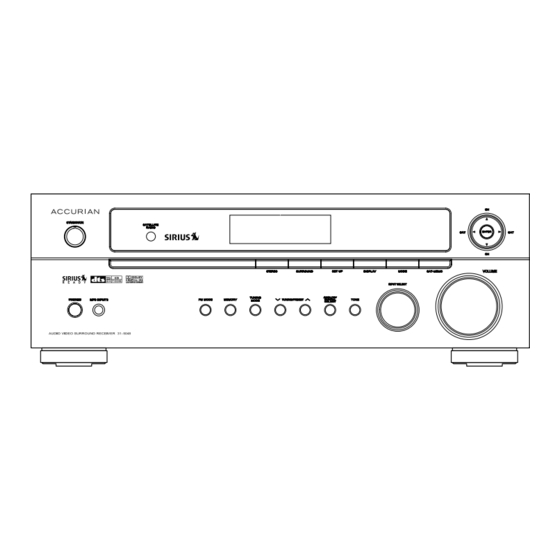
Page 24: Front Panel Controls
Front Panel Controls STANDBY/ON Press to switch the unit between standby and on. Power Indicator This LED lights red when the unit is in the standby mode to signal that the unit is ready to be turned on, when the unit is in operation, the indicator is off... - Page 25 TUNING/PRESET In tuner mode, use to tune in stations. ANALOG/DIGITAL SELECT Repeatedly press to select one of the digital inputs or the analog input for any source. TONE Use to adjust the level of bass and treble. INPUT SELECT Use to select functions. VOLUME Turn to adjust the volume.
-
Page 26: Remote Control
Use to select stereo mode or surround mode. Display Window Depending on the unit’s status, a variety of messages will appear here. SATELLITE RADIO (SIRIUS Function Direct Button) Use to select SIRIUS Satellite Radio function. Remote Control STANDBY Press to switch the unit between standby and on. - Page 27 CLEAR Use to remove a programmed preset radio station. OSD (Only SIRIUS Function) Use to display Sirius Satellite Radio Information on screen. As you press OSD, the display switches as shown below. CHANNEL INFORMATION SIRIUS SETUP ENTER When making a choice during the setup or confi...
- Page 28 TUNING MODE Press to select manual or preset tuning. TEST TONE Use to output the test tones for setting speaker levels. NIGHT When very dynamic movie soundtracks are played at low volume, such as late at night, you can use night mode to apply appropriate compression so that low-level program content is not lost and high level eff...
-
Page 29: Remote Sensor
SURROUND Use to select from the various surround modes. VOLUME (+/-) Press to adjust volume. MUTE Press to activate the mute function. DIMMER Press to adjust the brightness of the front display. SLEEP Press to set the sleep timer. Send Indicator Lights red when sending a signal. -
Page 30: Battery Installation
Battery Installation Remove the battery compartment cover. Insert the supplied two “AAA” batteries. Make sure that the batteries are inserted with their positive “+” and negative “-” poles positioned correctly. Close the cover until it clicks. If the distance required between the remote control and main unit decreases, replace the batteries with new ones. -
Page 31: Advanced Operation
Advanced Operation STANDBY/ON STANDBY NIGHT Press STANDBY/ON. Select the desired source with INPUT SELECT. TUNER (FM, AM) SIRIUS (OPTICAL, ANALOG) AUX (COAXIAL, ANALOG) DVD (OPTICAL, ANALOG) TAPE MP3 (1, 2) INPUT SELECT TONE VOLUME ANALOG/ DIGITAL SELECT SLEEP DIMMER MUTE VOLUME ANALOG/ DIGITAL SELECT... -
Page 32: Recording A Source
When DVD is selected, press ANALOG/DIGITAL SELECT to select OPTICAL or ANALOG in accordance with your connections. When AUX is selected, press ANALOG/DIGITAL SELECT to select COAXIAL or ANALOG in accordance with your connections. Recording a Source You can record a source such as a Compact Disc onto a cassette tape connected to the TAPE OUT jacks. -
Page 33: Sleep Timer Function
Sleep Timer Function This function allows you to preprogram the receiver to switch its own power off automatically. You can then enjoy the audio/video system for a specifi ed amount of time without having to worry about turning the unit off... -
Page 34: Radio Reception
Radio Reception FM MODE TUNER FM/AM TUNING MODE Select the TUNER mode by turning INPUT SELECT or press TUNER on the remote control. Select AM or FM by pressing FM/AM or turning INPUT SELECT. Press TUNING MODE to change to TUNING mode. This button is used to select MANUAL or PRESET scan mode. -
Page 35: Fm Mode
Or repeatedly press TUNING/PRESET station. The frequency changes by a fi xed step (FM: 100 kHz, AM: 10 kHz steps). Note: During AM reception, PURE STEREO or DSP STEREO appears on the receiver’s display if the stereo mode is selected using STEREO. However, the tuner receives mono and the sound does not change from mono to stereo. -
Page 36: Presetting
Presetting TUNER TUNING/PRESET This feature is used to store FM, AM broadcasting from Channel 1 to 30 respectively. Automatic Memory Presetting Select the tuner mode by turning INPUT SELECT or pressing TUNER on the remote control. Select the AM or FM by pressing FM/AM or turning INPUT SELECT. Press MEMORY for more than 2 seconds. -
Page 37: Manual Memory Presetting
While P_ _ is fl ickering, select a preset channel to store the station using TUNING/PRESET To store more stations, repeat Steps 3 to 6. SIRIUS Satellite Radio Tuner Sirius ID During the process of activating your Sirius subscription, you will need to provide your Sirius ID. -
Page 38: Direct Tuning
Repeatedly press OSD. The display toggles: CHANNEL INFORMATION -> SIRIUS SETUP -> Off OSD DISPLAY *CHANNEL INFORMATION* CHANNEL: 001/Hits 1 * CATEGORY: NAME ARTIST/COMPOSER : The Darkness SONG TITLE : Toxic S-MODE: NORMAL ANTENNA: EXCELLENT Channel Up/Down Pressing CH will increment or move up to the next channel. Pressing CH will decrement or move down to the next channel. - Page 39 Display Setting Pressing DISPLAY from the default display toggles: CATEGORY name -> ARTIST/COMPOSER name -> SONG TITLE name FL DISPLAY 001 Hits1 Category Up/Down If you want to listen to a diff erent entertainment category, press to activate the category. - First channel display in the next category.
- Page 40 Setting Skip Channel Press MODE. Press ENTER to set the channel skip mode. • To cancel, press ENTER. • If you do not operate the function within 10 seconds, the display automatically returns to the normal display. FL DISPLAY 005 Gold ENTER SKIP MODE OSD DISPLAY...
- Page 41 Example: To memory 010 CH to BAND C5 010 Bridge SAT-MEMO 010 Bridge _ _ POP Searching Channel Presets Press MODE twice. Press CH preset channels. To return to the normal display, press MODE. Sirius Set Up Press OSD twice. The SIRIUS ID is displayed. If you want to choose SIRIUS RESET, clear all the BAND PRESET or clear Skip Channel setting, press Press ENTER.
-
Page 42: Video Operations
Error Messages When problems occur with your SIRIUS tuner, a message appears on the display. State Home Tuner is not connected Antenna is not connected Sirius satellite no signal Video Operations VCR Dubbing (From AUX or DVD to VCR) Turn INPUT SELECT to select the source (AUX or DVD) to be recorded. -
Page 43: Deck Dubbing
Deck Dubbing (From AUX or DVD or VCR to Tape) Turn FUNCTION (source) to select the audio source (AUX, DVD, or VCR) to be recorded. If necessary, press ANALOG/DIGITAL SELECT to select ANALOG. Play back the source (AUX, DVD, or VCR). Operate the deck for recording. -
Page 44: Speaker Confi Guration
Speaker Confi guration... -
Page 45: Size Of Speakers
STANDBY ENTER It is important to perform speaker confi guration prior to using the surround sound decoder. It is possible to receive multi-channel surround sound without a center speaker, but for best results with Dolby Pro Logic IIx and Dolby Digital decoding, at least 5 speakers (Front Left, Center, Front Right, Surround Left, and Surround Right) should be used. - Page 46 lower than approx. 120 Hz will be output from the subwoofer. If the subwoofer is set to NONE and the front speakers are set to LARGE, then the sound may be output from both the left and right speakers. Note: For the center, surround, and surround back speakers, select NONE if no speaker is connected.
-
Page 47: Balancing Speaker Relative Volume (Output Level)
Balancing Speaker Relative Volume (Output Level) Press SET UP. SPEAKER SIZE appears on the display. Press . SPEAKER LEVEL appears. Press ENTER. FRONT L LEVEL (Level of Front Left) appears on the display. Press ENTER. FRONT L LEVEL 0 appears on the display. Press to change the setting. -
Page 48: Balancing Speaker Relative Volume
Balancing Speaker Relative Volume The test tone function is useful to adjust the relative volume between speakers. Once the balance is set, you don’t have to change the balance as long as the speakers aren’t moved. Press TEST TONE on the remote control. The test tone is emitted from each speaker in the following order at 3-second intervals. - Page 49 Dolby Digital audio coding includes such consumer formats as DVD and DTV. As with fi lm sound, Dolby Digital can provide up to fi ve full-range channels for left, center, and right channels, independent left and right surround channels, and a sixth (“.1”) channel for low-frequency eff ects. Dolby Surround Pro Logic II is an improved matrix decoding technology that provides better spatiality and directionality on Dolby Surround program material;...
- Page 50 DTS was introduced in 1994 to provide 5.1 channels of discrete digital audio into home theater systems. DTS brings you premium quality and discrete multi-channel digital sound to both movies and music. DTS is a multi-channel sound system designed to create full-range digital sound reproduction.
- Page 51 • Neo:6 off ers a music mode to expand stereo nonmatrix recordings into the fi ve-or six-channel layout, in a way which does not diminish the subtlety and integrity of the original stereo recording. DTS-ES Extended Surround is a new multi-channel digital signal format developed by DTS, Inc.
-
Page 52: Selecting A Surround Mode
DTS 96/24 off ers the following: Sound quality transparent to the original 96/24 master. Full backward compatibility with all existing decoders. (Existing decoders will output a 48 kHz signal) No new player required: DTS 96/24 can be carried on DVD-video, or in the video zone of DVD-audio, accessible to all DVD players. -
Page 53: Setting Up Surround Modes
Note: A program encoded with matrix surround information retains the surround information as long as the the broadcast is in stereo. Thus, movies broadcast by conventional TV stations, cable, pay-TV and satellite transmission with surround sound can be decoded by any analog surround modes such as Dolby Pro Logic ll Movie or DTS Neo:6 Cinema. -
Page 55: Stereo Mode
Stereo Mode STEREO Repeatedly, press STEREO. The receiver’s display shows the following three settings (refer to the table on page 54): PURE STEREO - This setting allows you to bypass STEREO DSP processors to enjoy pure high fi delity sound from 2-channel analog sources. -
Page 56: Troubleshooting
Troubleshooting To determine any problem with your receiver, always check the most obvious possible causes fi rst. If any problem still remains after you have checked the items below, consult your local RadioShack Store. Problem Amplifi er When listening to the music, the left and right speakers sound reversed. - Page 57 Problem Tuner A hissing noise occurs when listening in stereo mode, but not in mono. Noise is excessive in both stereo and mono broadcasts. Sound is distorted or the volume level drops. Sound distortion in stereo broadcasts. Surround Eff ects Important: The center and rear speakers only operate when the unit is set to a Surround Sound mode and the source material being played is recorded or broadcast in Dolby Digital, DTS, or Dolby Pro Logic surround sound.
-
Page 58: Specifi Cations
Problem Remote Control Remote control not working. Specifi cations Amplifi er Section Output Power (6 ohms) ...110 W x 6 ch (1 ch Driven, 0.9% THD, 1kHz) Audio Input Sensitivity/Impedance...*LINE: 300 mV/47 k ohms Output Level/Impedance ...VCR/TAPE REC: 300 mV/1 k ohms Frequency Response ...*LINE: 20 Hz –... -
Page 59: Video Section
Total Harmonic Distortion (1 kHz) Mono ...0.5% Stereo ...0.8% Frequency Response ...30 Hz – 15 kHz, +1/–3 dB Stereo Separation (1 kHz) ... 40 dB Signal-to-Noise Ratio Mono ... 70 dB Stereo ... 65 dB AM Tuner Section Tuning Range ...520 kHz – 1,710 kHz (10 kHz steps) Usable Sensitivity ... - Page 60 RF EMISSIONS INFORMATION This equipment has been tested and found to comply with the limits for a Class B digital device, pursuant to Part 15 of the FCC Rules. These limits are designed to provide reasonable protection against harmful interference in a residential installation. This equipment generates, uses, and can radiate radio frequency energy and, if not installed and used in accordance with the instructions, may cause harmful interference to radio communications.