
Related Manuals for Panasonic AJ-UFC1800


Summary of Contents for Panasonic AJ-UFC1800
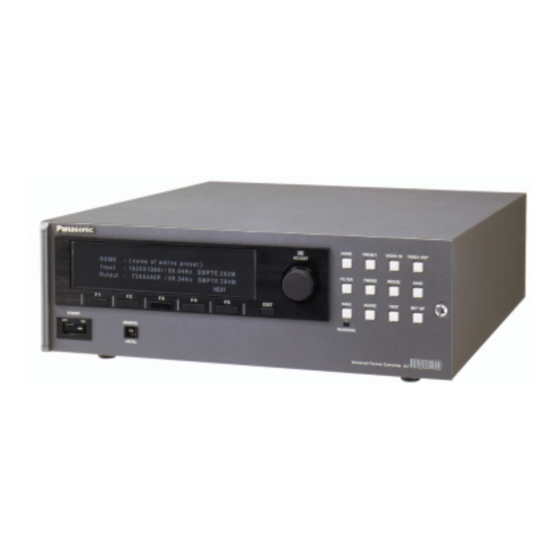
- Page 1 Panasonic AJ-UFC1800 Universal Format Converter System Reference, Ver. 1.11 Operating Software Level 1.49 June 15, 2000...
-
Page 2: Table Of Contents
Table Of Contents GENERAL..................................................................3 VERVIEW .................................. 3 EATURES ................................. 4 PECIFICATIONS CONTROLS ................................5 ................................5 RONT ANEL ................................7 ANEL CONNECTIONS................................. 9 ..............................9 NPUT EFERENCE ..............................9 UTPUT EFERENCE ............................9 LACK URST EFERENCE OPERATION ................................10 .............................. -
Page 3: Overview
Features Overview Overview The purpose of the AJ-UFC1800 is to create a spatial conversion from any input video format to any output video format. The input may be any standard video format (high definition or standard definition), and the output may also be any standard video format (high definition or standard definition) as long as it is has a related frame rate to the input format. -
Page 4: Specifications
Specifications [Power requirements:] Power supply : AC100V-120V , 50-60Hz AC220V-240V , 50-60Hz Power consumption : 115W [GENERAL:] Operating temperature : 5 to 40 • Operating humidity : 10% to 90% Weight : 18 Kg Dimensions : 424(W) x 133(H) x 500(D) [VIDEO INPUTS:] 1 HD SDI input –... -
Page 5: Controls
Controls Front Panel (1) POWER switch After ON is pushed, it will take about 30 seconds for the system to initialize. (2) CONTROL switch This is used to switch between operation from the front panel and the remote connectors on the rear panel. When it is set to REMOTE, front panel operation is disabled. - Page 6 (8) HOME key Selects the HOME menu. This displays the selected conversion and allows all settings to be viewed. (9) PRESET key Selects the PRESET menu. Allows up to sixteen system configurations to be saved and/or restored. (10) VIDEO IN key Selects the VIDEO IN menu.
-
Page 7: Rear Panel
Rear Panel Power supply section AC input socket This is connected to the power outlet using the supplied cable. GND (ground) terminal It is recommended that this unit be grounded when connected to other units. Digital video input/output section SD SERIAL IN connector SDTV serial digital signals are input to this connector. - Page 8 Remote control section (11) GPI connector (9P) Switch closure remote control connector. (12) REMOTE IN connector RS-232 serial remote input connector. (RS-232, 9P) Digital audio input/output section (13) DIGITAL AUDIO IN CH AES digital audio signals are input to these connectors. 1/2, 3/4, 5/6, 7/8 connectors (BNCx4) (14)
-
Page 9: Connections
Connections Input Reference Output Reference Missing output sync reference signal to EXT SYNC IN! Black Burst Reference... -
Page 10: Operation
Operation Basic operation Press VIDEO IN to select the input format and frame rate. VIDEO IN Press FORMAT(F1) to select an HxV value. Pressing the function key or turning the FORMAT knob will cycle through the range of choices. AUTO SD or AUTO HD will attempt to detect the input format if a signal is present. -
Page 11: Film Mode Operation
Press ZOOM H(F2) and ZOOM V(F3) to change the zoom factor. This will lock the ZOOM H,V horizontal and vertical adjustments together. Turn the knob to set the desired size. Press EXIT to go to the CROP menu. EXIT Press LEFT(F1), RIGHT(F2), TOP(F3) or BOTTOM(F4) to remove portions of the input L, R, T, B frame. - Page 12 For 24Hz interlaced(segmented) input: Press VIDEO IN to select the input format and 24Hz frame rate. VIDEO IN Press FORMAT(F1) to select an HxV interlaced value. Pressing the function key or FORMAT turning the knob will cycle through the range of choices. Press F RATE(F2) to select a 23.98/24Hz frame rate.
-
Page 13: Menu Tree
MENU TREE HOME VERSION DEFAULTS PRESET SAVE RECALL TITLE DELETE (DETAILS) TITLE <- -> SP/CLR SAVE VIDEO IN FORMAT F RATE PULLDN VIDEO OUT FORMAT F RATE FLD/FRM FILTER H RESP V RESP H ENH V ENH 2-D ENH TIMING SYSTEM REF IN GL TYPE... - Page 14 DIAG ALL↓ MON’D↓ TRIG’D↓ RETRIG MON/MASK ALL, MON’D, TRIG’D MASK TRG TYPE (RETRIG) AUDIO INPUT SELECTION CH1-4 CH5-8 SYNCHRO CH1-4 CH5-8 DELAY DELAY TEST SIG GEN SELECT F STORE SETUP BACKGROUND COLOR BG COL CUST R CUST G CUST B POWER UP STATE SELECT...
-
Page 15: Front Panel Controls
Front Panel Controls All operation of the AJ-UFC1800 is performed by means of the front panel controls. These controls are used to activate presets, select input and output formats, adjust control settings, and perform diagnostic testing. The front panel consists of a 4x40 character display, 5 function buttons, an EXIT button, 12 menu buttons, and a control knob for making adjustments. -
Page 16: Preset Menu
Preset Menu The PRESET menu is activated by pushing the PRESET button on the UFC front panel. This menu allows the user to look at preset system configurations that have been saved in memory. All system parameters are stored in a preset file, including input and output formats, zoom &... -
Page 17: Video In Menus
Video In Menus The VIDEO IN menus are activated by pushing the VIDEO IN button on the UFC front panel. These menus allow the user to select the input video format for the system. The format, and frame rate, are selected independently, with the system providing feedback to the user if the format &... -
Page 18: Filter Menu
Filter Menu The FILTER menu is activated by pushing the FILTER button on the UFC front panel. This menu allows the user to select the filtering and enhancement responses for the system. The user may select different responses or enhancement settings depending upon the type of conversion being done (up or down) or the nature of the source material (soft material may need more enhancement, noisy material may need less). -
Page 19: Resize Menus
FILM MODE T I M I N G > > F I L M M O D E “ A “ P O S 3 : 2 R E F T C S Y N C EXIT F1 – Activates knob to manually set the A Frame position or to offset the position from the nominal value when triggering from an external reference. -
Page 20: Gain Menus
PRESETS The FIT functions are used to automatically set up different aspect ration conversions from input to output. Some examples follow. If input=16x9 and output=4x3: then FIT H=letterbox, FIT V=side cut, FIT H&V=anamorphic squeeze. If input=4x3 and output=16x9: then FIT H=top&bottom cut, FIT V=side panel, FIT H&V=anamorphic stretch. -
Page 21: Diagnostics Menu
Diagnostics Menu The DIAGNOSTICS menu is activated by pushing the DIAG button on the UFC front panel. This menu shows any errors or warnings that have been detected by the system. Three submenus are available from the top menu: ALL, MONITORED &... -
Page 22: Audio Menus
Audio Menus The AUDIO menus are activated by pushing the AUDIO button on the UFC front panel. These menus allow the user to change audio routing and delay in the system, as well as enable or disable the audio synchronizers (sample rate converters). -
Page 23: Test Menus
Test Menus The TEST menu is activated by pushing the TEST button on the UFC front panel. This menu allows the user to activate the internal test pattern generator, select patterns, or activate the frame store feature. SIGNAL GEN T E S T > S I G G E N S E L E C T F S T O R E EXIT... - Page 24 TIME CODE-INPUT This menu allows the user to select the source for LTC and indicate drop frame or non-drop frame TC. S E T U P > T I M E C O D E - I N P U T S O U R C E D F M O D E EXIT...
- Page 25 LOCK This menu allows the user to set a system password by using the menu keys. S E T U P > > L O C K P A S S W D P R E S E T S C O N T R O L S EXIT F1 –...
-
Page 26: Error Messages
Error messages Message Error description Remedy DIO- NO SD DIG VIDEO INPUT No signal is detected on the Check SD input signal. SD serial input. DIO- NO HD DIG VIDEO INPUT No signal is detected on the Check HD input signal. HD serial input. -
Page 27: Others
CH 5/6 AUDIO CRC ERROR A checksum error was found Check cable and/or source. on the external audio signal. CH 7/8 AUDIO PARITY A parity error was found on Check cable and/or source. ERROR the external audio signal. CH 7/8 AUDIO CRC ERROR A checksum error was found Check cable and/or source. -
Page 28: Remote Connectors
Remote connectors The RS-232 serial port supports downloads of new system software and limited remote control operation. The GPI port allows remote selection of PRESETS 1-8 when the front panel REMOTE/LOCAL switch is in the “REMOTE” position. The GPI inputs are active low so that a connection between pins 1-8 and pin 9 will select the corresponding PRESET. - Page 29 30/29 Frame Time Code NDF <-> DF Conversion difference 00:00:00:00 24:01:22:26 00:00:03:17 24:01:26:13 00:00:03:18 00:00:00:00 -00:00:03:18 00:59:00:00 00:58:59:28 -00:00:00:02 00:59:00:01 00:58:59:29 -00:00:00:02 00:59:00:02 00:59:00:02 00:00:00:00 SYNC POINT 01:00:00:00 01:00:00:00 00:00:00:00 01:00:59:29 01:00:59:29 00:00:00:00 01:01:00:00 01:01:00:02 +00:00:00:02 1min. = 2Frame 01:01:59:27 01:01:59:29 01:01:59:28 01:02:00:02...
- Page 30 30/29 Frame Time Code NDF <-> DF Conversion difference 01:08:59:13 01:08:59:29 01:08:59:14 01:09:00:02 +00:00:00:18 01:09:00:00 01:09:00:18 01:09:59:11 01:09:59:29 01:09:59:12 01:10:00:00 +00:00:00:18 10min. = 18Frame 01:09:59:29 01:10:00:17 01:10:00:00 01:10:00:18 01:10:00:19 01:10:00:01 01:19:58:24 01:20:00:00 +00:00:01:06 01:29:58:06 01:30:00:00 +00:00:01:24 01:39:57:18 01:40:00:00 +00:00:02:12 01:49:57:00 01:50:00:00 +00:00:03:00 01:59:56:12...
- Page 31 30/29 Frame Time Code NDF <-> DF Conversion difference 18:58:55:06 19:00:00:00 +00:01:04:24 19:58:51:18 20:00:00:00 +00:01:08:12 20:58:48:00 21:00:00:00 +00:01:12:00 21:58:44:12 22:00:00:00 +00:01:15:18 22:58:41:24 23:00:00:00 +00:01:19:06 23:58:37:05 23:59:59:29 +00:01:22:24 23:58:37:06 24:00:00:00 +00:01:22:24 Irregular Value 23:59:37:06 24:01:00:02 +00:01:22:26 00:00:00:00 24:01:22:26...
- Page 32 30/29 -> 24/23 Frame Time Code NDF -> NDF Conversion 3:2 PullDown Actual Frame 30frame 24frame VIDEO OUTPUT Sequence difference 00:00:00:00 00:00:00:00 00:00:03:16 00:00:03:17 00:00:03:13. 00:00:03:18 00:00:03:14. 00:59:00:00 00:59:00:00 00:59:59:28. 00:59:59:29 00:59:59:29 00:59:00:23 00:59:59:29. 00:59:29:29. 00:59:00:23. SYNC POINT 0 01:00:00:00 01:00:00:00 01:00:00:00 00:00:00:00...
- Page 33 30/29 -> 24/23 Frame Time Code NDF -> NDF Conversion Actual Frame 30frame 24frame VIDEO OUTPUT Sequence difference 01:00:00:19. 01:00:00:19. 01:00:00:15. 01:00:00:20 01:00:00:20 01:00:00:16 01:00:00:20. 01:00:00:20. 01:00:00:16. 01:00:00:21 01:00:00:21. 01:00:00:22 01:00:00:17 01:00:00:22 01:00:00:21. 01:00:00:17. 01:00:00:22. 01:00:00:23 01:00:00:18 01:00:00:23 01:00:00:22. 01:00:00:18. 01:00:00:23.
- Page 34 30/29 -> 24/23 -> 30/29 Frame Time Code NDF -> NDF Conversion 3:2 PullDown Frame Actual NDF 30frame Sequence VIDEO OUTPUT NDF 30frame 00:00:00:00 00:00:00:00 00:00:03:16 00:00:03:16 00:00:03:17 00:00:03:17 00:00:03:18 00:00:03:18 00:59:00:00 00:59:00:00 00:59:59:28. 00:59:59:29. 00:59:59:28. 00:59:59:29 00:59:59:29 00:59:59:29 00:59:59:29. 00:59:59:29.
- Page 35 30/29 -> 24/23 -> 30/29 Frame Time Code NDF -> NDF Conversion Frame Actual NDF 30frame NDF 30frame Sequence VIDEO OUTPUT 01:00:00:19. 01:00:00:18. 01:00:00:19. 01:00:00:20 01:00:00:20 01:00:00:20 01:00:00:20. 01:00:00:20. 01:00:00:20. 01:00:00:21 01:00:00:22 01:00:00:21 01:00:00:21. 01:00:00:21. 01:00:00:21. 01:00:00:22 01:00:00:22 01:00:00:22 01:00:00:22. 01:00:00:22.
- Page 36 30/29 <-> 24/23 Frame Time Code NDF <-> NDF Conversion SlowPAL 25frame count 3:2 PullDown SlowPAL Actual VIDEO Frame 25frame NDF 30frame OUTPUT Sequence difference 00:00:00:00 00:01:12:00 -00:01:12:00 00:00:03:00 00:01:19:05 00:00:03:16 00:00:03:17 00:01:19:18. 00:00:03:18 00:01:19:19. 00:59:00:00 00:59:02:10 -00:00:02:10 00:59:59:28. 00:59:59:29 00:59:59:29 00:59:00:24 00:59:59:29.
- Page 37 30/29 <-> 24/23 Frame Time Code NDF <-> NDF Conversion SlowPAL Actual VIDEO Frame 25frame NDF 30frame OUTPUT Sequence difference 01:00:00:19. 01:00:00:19. 01:00:00:15. 01:00:00:20 01:00:00:20 01:00:00:16 01:00:00:20. 01:00:00:20. 01:00:00:16. 01:00:00:21 01:00:00:21. 01:00:00:22 01:00:00:17 01:00:00:22 01:00:00:21. 01:00:00:17. 01:00:00:22. 01:00:00:23 01:00:00:18 01:00:00:23 01:00:00:22.
- Page 38 30/29 <-> 24/23 Frame Time Code NDF <-> NDF Conversion SlowPAL Actual VIDEO Frame 25frame NDF 30frame OUTPUT Sequence difference 01:00:01:16 01:00:01:16. 01:00:01:17 01:00:01:12 01:00:01:17 01:00:01:16. 01:00:01:12. 01:00:01:17. 01:00:01:18 01:00:01:13 01:00:01:18 01:00:01:17. 01:00:01:13. 01:00:01:18. 01:00:01:19 01:00:01:19 01:00:01:14 01:00:01:19. 01:00:01:19. 01:00:01:14. 01:00:01:20 01:00:01:20 01:00:01:15...
- Page 39 30/29 <-> 24/23 Frame Time Code NDF <-> NDF Conversion SlowPAL Actual VIDEO Frame 25frame NDF 30frame OUTPUT Sequence difference 01:01:00:00 01:00:57:15 +00:00:02:10 1min. = 60Frame...
- Page 40 29 <-> 23 Frame Time Code DF <-> NDF Conversion 3:2 PullDown Frame NDF 29frame DF 29frame NDF 23frame Sequence difference 00:00:00:00 24:01:22:26 00:00:00:00 00:00:03:16 24:01:26:12 00:00:03:17 24:01:26:13 00:00:03:13. 00:00:03:18 00:00:00:00 00:00:03:14. 00:59:00:00 00:58:59:28 00:59:00:00 -00:00:00:02 00:59:00:01 00:58:59:29 00:59:00:02 00:59:00:02 00:59:00:01.
- Page 41 29 <-> 23 Frame Time Code DF <-> NDF Conversion Frame NDF 29frame DF 29frame NDF 23frame Sequence difference 01:00:00:19. 01:00:00:19. 01:00:00:15. 01:00:00:20 01:00:00:20 01:00:00:16 01:00:00:20. 01:00:00:20. 01:00:00:16. 01:00:00:21 01:00:00:21 01:00:00:21. 01:00:00:21. 01:00:00:17 01:00:00:22 01:00:00:22 01:00:00:17. 01:00:00:22. 01:00:00:22. 01:00:00:18 01:00:00:23 01:00:00:23 01:00:00:18.
- Page 42 29 <-> 23 Frame Time Code DF <-> NDF Conversion Frame NDF 29frame DF 29frame NDF 23frame Sequence difference 01:05:59:19 01:05:59:29 01:05:59:15 01:05:59:20 01:06:00:02 01:05:59:16 01:06:00:00 01:06:00:12 01:06:00:00 +00:00:00:12 01:06:59:16 01:06:59:28 01:06:59:17 01:06:59:29 01:06:59:13. 01:06:59:18 01:07:00:02 01:06:59:14. 01:07:00:00 01:07:00:14 01:07:00:00 +00:00:00:14 01:07:59:15 01:07:59:29...
- Page 43 29 <-> 23 Frame Time Code DF <-> NDF Conversion Frame NDF 29frame DF 29frame NDF 23frame Sequence difference 03:00:00:00 03:00:07:06 03:00:00:00 +00:00:07:06 03:59:49:06 04:00:00:00 03:59:49:07 04:00:00:01 03:59:49:05. 04:00:00:00 04:00:10:24 04:00:00:00 +00:00:10:24 04:59:45:18 05:00:00:00 04:59:45:14. 05:00:00:00 05:00:14:12 05:00:00:00 +00:00:14:12 05:59:42:00 06:00:00:00 05:59:42:00 06:00:00:00...
- Page 44 30/29 <-> 24/23 Frame Time Code DF <-> NDF Conversion SlowPAL 25frame count 3:2 PullDown SlowPAL Frame 25frame NDF 30frame DF 29frame Sequence difference 00:00:00:00 24:01:22:26 00:01:12:00 00:00:03:00 00:01:19:05 00:00:03:16 24:01:26:12 00:00:03:17 24:01:26:13 00:01:19:18. 00:00:03:18 00:00:00:00 00:01:19:19. 00:59:00:00 00:58:59:28 00:59:02:10 00:59:00:01 00:58:59:29 00:59:00:02...
- Page 45 30/29 <-> 24/23 Frame Time Code DF <-> NDF Conversion SlowPAL Frame 25frame NDF 30frame DF 29frame Sequence difference 01:00:00:19. 01:00:00:19. 01:00:00:15. 01:00:00:20 01:00:00:20 01:00:00:16 01:00:00:20. 01:00:00:20. 01:00:00:16. 01:00:00:21 01:00:00:21 01:00:00:21. 01:00:00:21. 01:00:00:17 01:00:00:22 01:00:00:22 01:00:00:17. 01:00:00:22. 01:00:00:22. 01:00:00:18 01:00:00:23 01:00:00:23 01:00:00:18.
- Page 46 30/29 <-> 24/23 Frame Time Code DF <-> NDF Conversion SlowPAL Frame 25frame NDF 30frame DF 29frame Sequence difference 01:04:00:00 01:04:00:08 01:04:59:20 01:04:59:28 01:04:59:21 01:04:59:29 01:04:59:22 01:05:00:02 01:05:00:00 01:05:00:10 01:05:59:19 01:05:59:29 01:05:59:20 01:06:00:02 01:06:00:00 01:06:00:12 01:06:59:16 01:06:59:28 01:06:59:17 01:06:59:29 01:06:59:18 01:07:00:02 01:07:00:00 01:07:00:14...
- Page 47 30/29 <-> 24/23 Frame Time Code DF <-> NDF Conversion SlowPAL Frame 25frame NDF 30frame DF 29frame Sequence difference 01:59:56:12 02:00:00:00 02:00:00:00 02:00:03:18 1Hr. = 3sec.18F 02:59:52:24 03:00:00:00 03:00:00:00 03:00:07:06 03:59:49:06 04:00:00:00 04:00:00:00 04:00:10:24 04:59:45:18 05:00:00:00 05:00:00:00 05:00:14:12 05:59:42:00 06:00:00:00 06:00:00:00 06:00:18:00 06:59:38:12...
- Page 48 30/29 <-> 24/23 Frame Time Code DF <-> NDF Conversion SlowPAL Frame 25frame NDF 30frame DF 29frame Sequence difference 20:00:00:00 20:01:08:12 21:00:00:00 21:01:12:00 22:00:00:00 22:01:15:18 23:00:00:00 23:01:19:06 23:58:37:05 23:59:59:29 23:58:37:06 24:00:00:00 Irregular Value 23:59:37:06 24:01:00:02 00:00:00:00 24:01:22:26 5 of 5...