Table of Contents
Advertisement
Quick Links
Advertisement
Table of Contents

Summary of Contents for Nabla Instruments MiniP7
- Page 1 MiniP7 Assembly and User’s Manual V2.03 ©2018 NALOG OMPUTER...
-
Page 2: Table Of Contents
4.3.1. Front Panel ....................11 4.3.2. Knobs ......................11 4.3.3. Connecting the Power Supply..............11 Playing the MiniP7 (User’s Manual) ................12 5.1. Stand Alone ......................12 5.1.1. Selecting and Deselecting Rhythms and Combinations ......... 12 5.2. Using External Clock and Sync ................13 5.2.1. -
Page 3: Thank You
It’s a unique clone for sound and feeling of the famous Minipops7 as used throughout several parts of world renown music by Jean Michelle Jarre. The MiniP7 has been designed to mimic the ‘spirit’ of the Minipops7 as good as possible. -
Page 4: Kit Content
3. Kit Content This summary is an overview of all parts in the kit with exclusion of the SMD populated PCB, the Front Panel and the speed knob. To be updated Manufacturer Order Comment Designator Description Picture Quantity Supplier 1 Supplier Part Number 1 Code Bolt_M2.5x6_+ Bolt1, Bolt2, Bolt3, Bolt4, Bolt5,... -
Page 5: Assembling The Kit (Assembly Manual)
4. Assembling the Kit (Assembly Manual) 4.1. Assembly of TH Components and Spacers See Technical Spec for enlarged view. 4.1.1. Population of the LEDs Mount the LEDs with the pin enlargement just above the PCB. Long Pin is Anode and should be the upper pin. -
Page 6: Population Of The Trimmers
4.1.2. Population of the Trimmers Done T73YP201KT20 200 Ohm marked 201 T73YP501KT20 P5, P11 500 Ohm marked 501 T73YP102KT20 P3, P12, P13, P16, P18 1 k Ohm marked 102 T73YP103KT20 P8, P10 10 k Ohm marked 103 T73YP504KT20 500 k Ohm marked 504... -
Page 7: Population Of The Slide Pots & Potentiometer
4.1.3. Population of the Slide Pots & Potentiometer Done 652-PTA45432015DPA10 P2, P4, P9, P14, P15 10k – 50k Slide Pot 100KB_PTV09_4025FB104 9mm pot meter 100k Lin (can be 50k as well) -
Page 8: Placing The Rocker Switches
4.1.4. Placing the Rocker Switches Sw 12 is only used as a SPDT, while Sw 11 is used as a DPDT Done Sw 11, Sw 12 M2021ES1W01 DPDT switch NKK 4.1.5. Population of the Jacks Although this can be done at this time, it may be better to assemble the jacks after the PCB has been put on the front panel. -
Page 9: Population Of The Push Buttons
Done 1502-03 Jack 3.5mm J1, J7, J8 4.1.6. Population of the Push Buttons Done B3W-9000-Y1N Sw1, Sw2, Sw3, Sw4, Sw5, Sw6, Sw7, Sw8, Sw9, Sw10 JB15HAP-1H Sw13... -
Page 10: Population Of The Header
4.1.7. Population of the Header The boxed header has to be mounted on the bottom side of PCB. Pin 1 should be at the lower edge of the board. Done 1056437 Boxed Header 2x5 HDR 1 4.1.8. Mounting of the Spacers Mount 6 spacers at their positions using an M2.5 x 6 mm bolt. -
Page 11: Tuning The Minip7
4.2. Tuning the MiniP7 A hidden software feature allows the instruments to be triggered by the rhythm select buttons. As there are 15 instruments and only 10 rhythm select buttons, the instruments have been split into two groups. One 8 instruments group in the upper rhythm bank and a 7 instruments group in the lower rhythm bank. -
Page 12: White Noise Level
Relative trimmer position White Noise Level 4.2.2. Frequencies Not all instruments of the MiniP7 need to be tuned at time of assembly. The following table provides the approximate frequencies of the tunable instruments to be tuned to. Using a frequency meter or audio analyzer on PC may be a quite big job to get the tuning done. -
Page 13: Mounting The Front Panel
After assembly of the Front Panel, it’s time to place the knobs. 4.3.3. Connecting the Power Supply. The MiniP7 has a selectable power supply to operate either under 12V or 15V conditions. Place both jumpers on the right side for 15V operation and on the left side for 12V operation. -
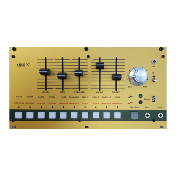
Page 14: Playing The Minip7 (User's Manual)
5.1. Stand Alone 5.1.1. Selecting and Deselecting Rhythms and Combinations The MiniP7 does not have a ‘program’ memory, so it can not recall its last used rhythm. Therefor the MiniP7 starts up without any rhythm selected. Tambourine, Guiro and Quijada are always active and can be played without any of the rhythms active. -
Page 15: Using External Clock And Sync
5.2. Using External Clock and Sync 5.2.1. Introduction to external clocking. The MiniP7 has been foreseen with two extra inputs to provide the capability to use external applied clocking and resetting/syncing. The MiniP7 internal system mimics the original’s internal clocking system which switches between 12 and 16 counts per measure depending on the selected rhythm. -
Page 16: Specifications
6. Specifications 6.1. Technical Spec. PCB dimensions 242 x 110 x 1.6 Power Supply + 12V or 15V @ 300mA - 12V or 15 V @ 120 mA Front Panel 3U by 48 HP Analog Output Standard line level 0.7 Vrms External Sync Vin min = 3V3. -
Page 17: Dimensions
6.2. Dimensions... -
Page 18: Ref Des Positions
6.3. Ref Des Positions...