
Related Manuals for Sega SEGA RALLY CHAMPIONSHIP TWIN TYPE


Summary of Contents for Sega SEGA RALLY CHAMPIONSHIP TWIN TYPE
- Page 1 1st PRINTING MAR 98 TWIN TYPE OWNER’S MANUAL OWNER’S MANUAL OWNER’S MANUAL OWNER’S MANUAL OWNER’S MANUAL SEGA ENTERPRISES, USA MANUAL NO. 4200-6374-03...
-
Page 2: Table Of Contents
TABLE OF CONTENTS INTRODUCTION OF THE OWNERS MANUAL GENERAL PRECAUTIONS 1. PRECAUTIONS TO BE HEEDED FOR OPERATION 2. NAME OF PARTS 3. ACCESSORIES 4. ASSEMBLY AND INSTALLATION 9~15 5. PRECAUTIONS TO BE HEEDED WHEN MOVING MACHINE 6. CONTENTS OF GAME 17~21 7. - Page 3 Warranty Your new Sega Product is covered for a period of 90 days from the date of shipment. This certifies that the Printed Circuit Boards, Power Supplies and Monitor are to be free of defects in workman- ship or materials under normal operating conditions. This also certifies that all Interactive Control Assemblies are to be free from defects in workmanship and materials under normal operating condi- tions.
-
Page 4: Introduction Of The Owners Manual
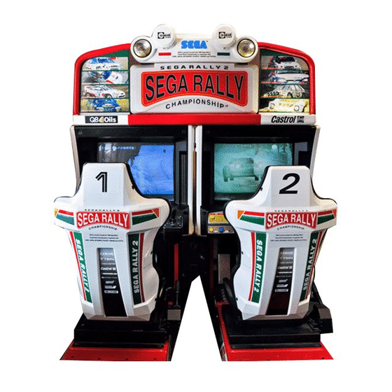
29” NANAO MONITOR (X2) INTRODUCTION OF THE OWNERS MANUAL SEGA ENTERPRISES, LTD., has for more than 30 years been supplying various innovative and popular amusement products to the world market. This Owners Manual is intended to provide detailed descriptions together with all the necessary installation, game settings and parts ordering information related to the RALLY 2 TWIN VERSION, a new SEGA product. -
Page 5: General Precautions 2~3
General Precautions Follow Instructions: All operating and use instructions should be followed. Attachments: Do not use attachments not recommended by the product manufacturer as they may cause hazards. Accessories: Do not place this product on an unstable cart, stand, tripod, bracket, or table. The product may fall, causing serious injury to a child or adult, and serious damage to the product. - Page 6 Safety Check: Upon completion of any service or repairs to this product, ask the service technician to perform safety checks to determine that the product is in proper operating condition. Heat: The product should be situated away from heat sources such as radiators, heat registers, stoves, or other prod- ucts (including amplifiers) that produce heat.
-
Page 7: Precautions To Be Heeded For Operation 4~5
1 . PRECAUTIONS TO BE HEEDED FOR OPERATION In order to prevent accidents, be sure to comply with the following points before and during operation. PRECAUTIONS TO BE HEEDED FOR OPERATION BEFORE STARTING THE OPERATION In order to avoid accidents, check the following before starting the operation: Check if all of the adjusters are in contact with the surface. - Page 8 PRECAUTIONS TO BE HEEDED DURING OPERATION To avoid injury and accidents, those who fall under the following catagories are not allowed to play the game: * Intoxidated persons * Those who have high blood pressure or heart problems. * Those who have experienced muscle convulsion or loss of consciousness when playing video games, etc.
-
Page 9: Name Of Parts
2 . NAME OF PARTS WEIGHT WIDTH LENGTH HEIGHT GAME SPECIFICATIONS ~ 1250 LBS. All measurements are in inches Weight-DURING SHIPPING BILLBOARD 64” 27” 24” 105 LBS. 514 LBS. 33” 66” 61” COCKPIT (PER SEAT) COIN CHUTE TOWER 12.5” 18” 23”... -
Page 10: Accessories 7~8
3 . ACCESSORIES... - Page 11 THE SHIPMENT METHOD DESCRIBED BELOW ONLY APPLIES TO ‘MODEL 3’ BOARDS CONTAINED IN THE FOLLOWING GAMES: LOST WORLD, VIRTUA FIGHTER 3, SUPER GT, SEGA BASS FISHING, STRIKER 2 HARLEY DAVIDSON, RALLY 2 !!NEVER SHIP MODEL 3 GAME BOARDS !!NEVER SHIP MODEL 3 GAME BOARDS...
-
Page 12: Assembly And Installation
4 . ASSEMBLING AND INSTALLATION Assembling should be performed as per this manual. Since this is a complex machine, erroneous assembling may cause damage to the machine, or malfunctioning to occur. When assembling, be sure to perform work by plural persons. Depending on the assembly work, there are some cases in which performing the work by a single person can cause personal injury or parts damage. - Page 13 Place the two cockpits side by side. Position the 1P cabinet, which has the power cord at the left hand side, as shown in the diagram. Install the coin chute tower in between the two cabinets. Open the coin chute door and cashbox door to secure with the 4 hex bolts from are fastened temporarily.
- Page 14 ASSY OF THE BILLBOARD Due to its large size, it is very difficult for one person alone to install the billboard, Make sure 2 or more persons are available to perform this work. Attempting to perform the installation alone can cause an accident. Mount Billboard on tbothcabinets and secure with the 4 hexgaonal bolts for each cabinet.
- Page 15 SECURING IN PLACE (ADJUSTER ADJUSTMENT) Be sure to have all the Adjusters make contact with the surface. Un- less the Adjusters come into contact with the surface, the Cabinet can move of itself, causing an accident. This machine has 8 each of casters and adjusters (shown below). When the installation position is determined, cause the adjusters to come into contact with the floor directly, make adjustments in a manner so that the casters will be raised approximately 5mm.
- Page 16 POWER SUPPLY Ensure that the power cord is not exposed on the surface (passage, etc.). If exposed, they can be caught and are susceptible to damage. If damaged, the cord can cause an electric shock or short circuit. Ensure that the wiring position is not in the customer's passage way or the wiring has protective covering.
- Page 17 ASSEMBLING CHECK The TEST MENU allows for each part of the cabinet to be checked, the Monitor to be adjusted, and the coin and game related various functions to be performed. MEMORY TEST Selecting the MEMORY TEST on the test mode menu screen causes the on-board memory to be tested automatically.
- Page 18 SOUND TEST In the TEST mode, selecting SOUND TEST causes the screen, on which sound related BD and wiring connec- tions are tested, to be displayed. be sure to check if the sound is satisfactorily emitted from each of speaker and EFFECT SE_CHECK1 the sound volume is appropriate.
-
Page 19: Precautions To Be Heeded When Moving Machine
5 . PRECATIONS TO BE HEEDED WHEN MOVING THE MACHINE When moving the machine, be sure to pull out the plug from the power supply. Moving the machine with the plug as is inserted can damage the power cord and cause a fire or elec- tric shock. -
Page 20: Contents Of Game 17~21
6 . CONTENTS OF GAME The following explanations apply to the case the product is functioning satisfactorily. Should there be any moves different from the following contents, some sort of faults may have occured. Immediately look into the cause of the fault and eliminate the cause thereof to ensure satisfactory operation. - Page 21 WHEN PLAYING IN TH ECHAMPIONSHIP MODE Note: In the interactive play, CHAMPIONSHIP MODE can not be selected. The car select mode appears. Select from among 6 types. Depending on the type of car, your operat- ing sensation may somewhat vary. Choose the desired car by turning the Steering Wheel, and confirm with the Accelerator Pedal.
- Page 22 On the upper left portion of the screen, total time & lap time are displayed. The remaining time is shown at the top center and navigation icon is seen at the loer part of the top center. on the upper right-hand side, the present player’s position as well as the stage’s top 3 times are displyed.
- Page 23 WHEN PLAYING IN THE PRACTICE MODE The Course Select mode appears. Turn the Steering Wheel to select and confirm with pedal. In case of communica- tion play, the course is selected by majority. The Car Select Mode appears. Select from among the 6 types.
- Page 24 The NAME ENTRY MODE appears. Turn the Steering Wheel to choose input characters, and confirm with pedal. After inputing the 3 characters, game start On the upper left portion of the screen, total time & lap time are displayed. The remaining time is shown at the top center and navigation icon is seen at the loer part of the top center.
-
Page 25: Explanation Of Test And Data Display 22~32
7 . EXPLANATION OF TEST AND DATA DISPLAY By operating the switch unit, periodically perform the tests and data check. When installing the machine intitally or collecting cash, or when the machine does not function correctly, perform checking in accordance with the explanations given in this section. -
Page 26: Switch Unit And Coin Meter
7 - 1 SWITCH UNIT AND COIN METER Never touch places other than those specified. Touching places not specified can cause electric shock and short circuit. Adjust to the optimum sound volume by considering the environmental requirements of the installation location. If the COIN METER and the game board are electrically disconnected, game play is not possible. -
Page 27: Test Mode
7 - 2 TEST MODE This mainly checks if the operation of the game BD is accurate, and allows for COIN ASSIGNMENTS/GAME ASSIGNMENTS setting and Projector adjustments. T h e F o l l o w i n g F I G U R E S / T A B L E S s h o w t h e f a c t o r y r e c o m m e n d e d s e t t i n g s . T h e F o l l o w i n g F I G U R E S / T A B L E S s h o w t h e f a c t o r y r e c o m m e n d e d s e t t i n g s . -
Page 28: Steering Reaction Test
7 - 4 STEERING REACTION TEST This test allows Steering Wheel reaction mechanism to be tested and eaction force to be set. Press the Service Button to STEERING REACTION TEST bring the arrow to the desitred item to be selected, and press the Test Button to enter the selected item. -
Page 29: Input Test
7 -5 INPUT TEST Select INPUT TEST to have the screen shown below appear and to observe the status of each switch and the Control Panel’s each V.R. Value. Periodically check the status of each switch and V.R. on this screen. By pressing each switch, if the display onthe right-hand side of the name of each switch changes to ON from OFF, the SW INPUT TEST... -
Page 30: Sound Test
7 - 7 SOUND TEST SOUND TEST This enables sound used in the game to be checked. Sound related memory and each speaker are checked. EFFECT: EFFECT SE_CHECK1 Sound effects during game. VOICE VO_30 VOICE: B.G.M. BM_ADV1 SPEAKER VO_FRONT Voice of announcement and naration. BGM VOLUME LEVEL 9/15 SOUND OFF... -
Page 31: Game Assignments
7 - 9 GAME ASSIGNMENTS Selecting the GAME ASSIGNMENTS in the MENU mode causes the present game settings to be displayed and also the game settings changes (game difficulty, etc.) can be made. Each item displays the following content. SETTING CHANGE PROCEDURE Setting changes cannot be stored unless the TEST BUTTON is pressed while the arrow is on EXIT. -
Page 32: Coin Assignments 29~31
7 - 10 COIN ASSIGNMENTS The “COIN ASSIGNMENTS” mode permits you to set the start number of credits, as well as the basic numbers of coins and credits. This mode expresses “how many coins correspond to how many credits.” SETTING CHANGE PROCEDURE Setting changes cannot be stored unless the TEST BUTTON is pressed while the arrow is on EXIT. - Page 33 TABLE 7.10a COIN/CREDIT SETTING (COIN CHUTE COMMON TYPE) SETTING FUNCTIONING OF CHUTE#1 SETTING #1 1 COIN 1 CREDIT SETTING #2 1 COIN 2 CREDITS SETTING #3 1 COIN 3 CREDITS SETTING #4 1 COIN 4 CREDITS SETTING #5 1 COIN 5 CREDITS SETTING #6 1 COIN...
- Page 34 MANUAL SETTING Selecting MANUAL SETTING in the COIN ASSIGNMENTS mode displays the following screen. MANUAL SETTING COIN TO CREDIT 1 COIN 1 CREDIT BONUS ADDER NO BONUS ADDER COIN CHUTE #1 MULTIPLIER 1 COIN COUNTS AS 1 COIN COIN CREDIT COIN CHUTE #2 MULTIPLIER 1 COIN COUNTS AS 1 COIN COIN...
-
Page 35: Bookkeeping
7 - 11 BOOKKEEPING Choosing BOOKKEEPING in the MENU mode displays the data of operating status up to the present are shown on 2 pages. Press the TEST BUTTON to proceed to PAGE 2/2. COIN CHUTE#*: BOOKKEEPING PAGE1/2 Number of coins put in each Coin Chute. COIN CHUTE #1 XXXXXXXXXXX COIN CHUTE #2... -
Page 36: Handle Mecha
8. HANDLE MECHA In order to prevent an electric shock and short circuit, be sure to turn power off before performing work by touching the interior parts of the product. Be careful so as not to damage wirings. Damaged wiring can cause an electric shock or short circuit accident. -
Page 37: Replacing And Adjusting The Handle's Vr
8 - 2 REPLACING AND ADJUSTING THE HANDLE’S VR Never touch places other than those specified. Touching places not specified can cause electric shock and/or short circuit. After the replacement or adjustment of the VR, be sure to set the variable value of the VR in the test mode’s Volume Setting. -
Page 38: Greasing
8 - 3 GREASING Never touch places other than those specified. Touching places not specified can cause electric shock and/or short circuit. After the replacement or adjustment of the VR, be sure to set the variable value of the VR in the test mode’s Volume Setting. Apply greasing to the Volume gear mesh portion every 3 months. -
Page 39: Shift Lever
9. SHIFT LEVER In order to prevent electric shock and short circuit, be sure to turn off the power before performing work on the interior parts of the product. Be careful not to damage wiring. Damaged wiring can cause electric shock or short circuit. -
Page 40: Switch Replacement
9 - 2 SWITCH REPLACEMENT Each microswitch is secured with 2 screws. Remove the 2 screws and replace the Microswitch. After replacing the Switch, check to see if the switch is inputted as per Shift Lever operation in the Test Mode.d... -
Page 41: Accel & Brake
10. ACCEL & BRAKE(S) In order to prevent an electric shock and short circuit, be sure to turn power off before performing work by touching the interior parts of the product. Be careful so as not to damage wirings. Damaged wiring can cause an electric shock or short circuit accident. -
Page 42: Greasing To Foot Brake And Accel
Check Volume values in the Test Mode. Since work is performed inside the energized cabinet, be very careful so as not to touch undesignated portions. Touching places not specified can cause an electric shock or short circuit. Take out the 2 truss screws and remove the Front Cover from the Accel. -
Page 43: Greasing To Hand Brake
In order to prevent an electric shock and short circuit, be sure to turn power off before performing work byt ouching the interior parts of the product. Be careful so as not to damage wirings. Damaged wiring can cause an electric shock or short circuit accident. -
Page 44: Coin Selector
11 . COIN SELECTOR HANDLING THE COIN JAM If the coin is not rejected when the REJECT BUTTON is pressed, open the coin chute door and open the selector gate. After removing the jammed coin, put a normal coin in and check to see that the selector correctly functions. - Page 45 OPTIONAL DOLLAR BILL ACCEPTOR THE COIN DOOR ASSEMBLY USED ON RALLY 2 Twin Version RALLY 2 Twin Version RALLY 2 Twin Version RALLY 2 Twin Version RALLY 2 Twin Version COMES EQUIPPED TO ACCEPT A DOLLAR BILL ACCEPTOR. ALL NEEDED WIRING CONNECTIONS ARE CONVIENENTLY LOCATED INSIDE THE GAME FOR THIS APPLICATION.
-
Page 47: Monitor 44~46
(plug) before starting work. Proceeding the work without following this instruction can cause electric shock of malfunctioning. Using the monitor by converting it without obtaining a prior permission is not allowed. SEGA shall not be liable for any malfunctioning and accident caused by said conversion. - Page 48 For the purpose of static prevention, special coating is applied to the CRT face of this product. To protect the coating, pay attention to the following points. Damaging the coating film can cause electric shock to the customers. For the caution to be heeded when clearing, refer to the Section of Periodic inspection Table.
-
Page 50: Replacement Of Fluorescent Lamp And Lamps 47~48
13. REPLACEMENT OF FLUORESCENT LAMP AND LAMPS When performing the work, be sure to turn power off. Working with power on can cause an electric shock or short circuit acci- dent. The Fluorescent Lamp, when it gets hot, can cause burns. Be very careful when replacing the Fluorescent Lamp. -
Page 51: Replacement Of Lamps
13 - 2 LAMP REPLACEMENT Remove Wire Covers A and B Disconnect the connector, take out the screw to remove the Lamp Unit, and replace the lamp. -
Page 52: Periodic Inspection Table
Move the Seat to the rearmost portion and apply spray greasing to the portion shown at the right once every 3 months by using NOK KLUBER L60 or GREASE MATE SEGA PART No. 090-0066. After greasing, move seat a few times forward and backward so as to allow the grease to be applied all over uniformly. -
Page 53: Troubleshooting
15. TROUBLESHOOTING Should trouble occur, first check connector connections. PROBLEMS CAUSE COUNTERMEASURES With Main SW Power is not supplied. Plug in correctly ON, no activation Power supply/voltage is not correct. Make sure that power supply/voltage is correct. AC main fuse causes the Check fuse. -
Page 54: Game Board 51~55
16. GAME BOARD In order to prevent an electrical shock, be sure to turn power off before performing work by touching the interior parts of the product. Be careful so as not to damage wirings. Damaged wiring can cause an electric shock or short circuit accident. -
Page 55: Replacment Of Fuse
16 - 2 REPLACEMENT OF FUSE In order to prevent an electric shock, be sure to turn power off before performing work by touching the interior parts of the product. Be careful so as not to damage wirings. Damaged wiring can cause an electric shock or short circiut accident After eliminating the cause of the blowing of fuse, replace the fuse. -
Page 56: Composition Of The Game Board
16 - 3 COMPOSITION OF GAME BOARD GAME BD SRT TWIN (833-13373) NOTE: THIS PICTURE IS FOR REFERENCE ONLY!! UNIT IS NOT TO BE OPENED. EXPOSING THE GAME BD FOR ANY REASON MAY VOID WARRANTY. -
Page 57: Error Display
16 - 4 ERROR DISPLAY (DRIVE CONTROL BOARD) Be Careful so as not to damage wirings. Damaged wirings can cause an electric shock or short circuit accident. Do not touch places other than those specified. Touching places not specified can cause an electric shock or short circuit accident. - Page 58 If ERROR display is shown on the screen, incline the Seat WITHOUT TURNING POWER OFF, and remove Back Lid B to check the 7-SEG display ont he Drive Control Board. At this time, if the power is turned off, each of the Er 23, 24, and 25 which could have occured during operation may not be displayed.
-
Page 59: Communication Play
17. COMMUNICATION PLAY Before performing between-cabinets connection work, be sure to turn the Power SW OFF and unplug the power plug from the wall socket. Failure to observe this can cause electric shock and/or short circuit accidents. Perform assembling as shown in this manual. Erroneous assembling can cause electric shock accidents and malfunctioning. - Page 60 To assemble your Rally 2 Twin Game locate the Left Cabinet (side with on/off switch), Cash Box Tower, and Right Side Cabinet. In the parts bag located in the cash box, locate the Opto Cable. this will be needed later, to connect together the opto connections on the rear of the Cash Box Tower.
-
Page 62: Setting For Communication Play
17 - 3 SETTING FOR COMMUNICATION PLAY During communication play, if communication is interrupted due to a certain cause, ERROR MESSAGE will be displayed, then NETWORK check mode appears on the screen automatically. Cause all of the seats to enter the Test Mode and change the GAME ASSIGNMENTS of each seat for communication play. -
Page 63: Design Related Parts 60~61
18. DESIGN RELATED PARTS... - Page 64 DESIGN RELATED PARTS...
-
Page 65: Parts List 62~103
19. PARTS LIST TOP ASSYSEGA RLLY 2 TWIN... - Page 66 TOP ASSY SEGA RALLY2 TWIN ITEM NO. PART NO. DESCRIPTION SRT-10001 ASSY COCKPIT 1P SRT-11001 ASSY COCKPIT 2P SRT-0200 ASSY BILLBOARD SRT-0300 ASSY COIN CHUTE TOWER 422-0663-01 SUB INSTR SH SRT TWIN ENG 421-8543 STICKER CABINET L 421-8544 STICKER CABINET R...
- Page 67 ASSY BILLBOARD (SRT-0200) ITEM NO. PART NO. DESCRIPTION SRT-0201-01 BILLBOARD FRAME EXP SRT-0202 ASSY BILLBOARD BOX SRT-0206 ASSY LIGHT COVER SRT-0215 ASSY FL BOX L SRT-0218 WIRE COVER A SRT-0219 WIRE COVER B SRT-0221 WIRE COVER L SRT-0222 WIRE COVER R SRT-0227 ASSY FL BOX R...
- Page 68 ASSY BILLBOARD BOX (SRT-0202) ITEM NO. PART NO. DESCRIPTION SRT-0203 BILLBOARD CASE SRT-0204 BILLBOARD LID SRT-0205 BILLBOARD 253-5457 FL HOLDER LOCAL PURCHASE ASSY FL 20W EX W/CONN HIGH S...
- Page 69 ASSY LIGHT COVER (SRT-0206) ITEM NO. PART NO. DESCRIPTION SRT-0207 LIGHT COVER SRT-0208 LIGHT COVER BASE SRT-0209 L BRKT SRT-0210 LIGHT COVER BRKT SRT-0211 LENS HOLDER SRT-0212 LIGHT BRKT SRT-0213 LAMP UNIT 253-5461 LIGHT COVER CIBIE 275-0134 LENS 105-5325 REFLECTOR 280-5328 RUBBER PACKING...
- Page 70 LAMP UNIT (SRT-0213) ITEM NO. PART NO. DESCRIPTION SRT-0214 LAMP BRKT 390-6567 LAMP 110V 15W YELLOW 214-0110 BULB SKT...
- Page 71 ASSY FL BOX L (SRT-0215) ITEM NO. PART NO. DESCRIPTION SRT-0216 FL BOX L SRT-0217 FL COVER PLATE SRT-0223 SIDE COVER L SRT-0225 SIDE COVER BRKT L LOCAL PURCHASE ASSY FL 6W SD W/CONN S...
- Page 72 ASSY FL BOX R (SRT-0227) ITEM NO. PART NO. DESCRIPTION SRT-0220 FL BOX R SRT-0217 FL COVER PLATE SRT-0224 SIDE COVER R SRT-0226 SIDE COVER BRKT R LOCAL PURCHASE ASSY FL 6W SD W/CONN S...
- Page 73 ASSY COINCHUTE TOWER (SRT-0300)
- Page 74 ASSY COINCHUTE TOWER (SRT-0300) ITEM NO. PART NO. DESCRIPTION SRT-0350 SW UNIT SPG-0301 COIN CHUTE TOWER DYN-0302Y COIN METER BRKT DP-1167 TNG LKG BOX-CASH CASH BOX DYN-0305 TOWER BRKT 105-5202 HOLE COVER SPG-0302 WIRE BOX SPG-0303 WIRE BOX LID 220-5237-92 ASSY C.C.
- Page 75 SW UNIT (SRT-0350) ITEM NO. PART NO. DESCRIPTION UCQ-1035 SWITCH BRKT 509-5028 SW PB 1M 220-5296 VOL CONT 5KOHMx2 +/-10% RV24G 601-0042 KNOB 22MM...
- Page 76 ASSY COCKPIT 1P (SRT-10001) ASSY COCKPIT 2P (SRT-11001)
- Page 77 ASSY COCKPIT 1P (SRT-10001) ASSY COCKPIT 2P (SRT-11001) ITEM NO. PART NO. DESCRIPTION SRT-20001 ASSY MAIN BASE 1P SRT-21001 ASSY MAIN BASE 2P SRT-1030 ASSY MONITOR COVER L 1P SRT-1040 ASSY MONITOR COVER L 2P SRT-1035 ASSY MONITOR COVER R 1P SRT-1045 ASSY MONITOR COVER R 2P SRT-12001-01...
- Page 78 ASSY MONITOR COVER L 1P (SRT-1030) ASSY MONITOR COVER L 2P (SRT-1040) ITEM NO. PART NO. DESCRIPTION SRT-1031 COVER PANEL L 1P SRT-1031-A COVER PANEL L BLANK SPG-1100 ASSY SPEAKER DYN-1032 MASK BRKT...
- Page 79 ASSY MONITOR COVER R 1P (SRT-1035) ASSY MONITOR COVER R 2P (SRT-1045) ITEM NO. PART NO. DESCRIPTION SRT-1046-A COVER PANEL R BLANK SRT-1046-01 COVER PANEL R 2P EXP SPG-1100 ASSY SPEAKER DYN-1032 MASK BRKT...
- Page 80 ASSY SPEAKER (SPG-1100) ITEM NO. PART NO. DESCRIPTION INY-1701 SPEAKER BRKT 130-5152 SPKR BOX MINI DOME 12W...
- Page 81 ASSY CONTROL PANEL TWIN EXP (SRT-12001-01)
- Page 82 ASSY CONTROL PANEL TWIN EXP (SRT-12001-01) ITEM NO. PART NO. DESCRIPTION SPG-2001 STEERING WHEEL DYN-1209X HANDLE COLLAR SPG-2002 STEERING EMBLEM SRT-1201-01 CONTROL PANEL COVER ENG SPG-1205 CONTROL PANEL BRKT DYN-1222 SHIFT COVER A DYN-1223X SHIFT COVER B SPG-1203 FAN BRKT SPG-1204 SPL BLT M8 SPG-2500...
- Page 83 ASSY HANDLE MECHA (SPG-2500)
- Page 84 ASSY HANDLE MECHA (SPG-2500) ITEM NO. PART NO. DESCRIPTION SPG-2501 HANDLE BASE SPG-2502 BASE LID SPG-2503 HANDLE SHAFT SPG-2504 PULLEY 20 S5M SPG-2505 PULLEY 60 S5M SPG-2506 MOTOR BRKT SPG-2507 VR BRKT SPG-2108 STOPPER BOLT SPG-2109 STOPPER RUBBER SPG-2453 KEY 4X4X40 ASK-3502 MOTOR SPACER ASK-3503...
- Page 85 ASSY 4 SPEED SHIFTER (SPG-2150)
- Page 86 ASSY 4 SPEED SHIFTER (SPG-2150) ITEM NO. PART NO. DESCRIPTION SPG-2151 SHIFT KNOB SPG-2152 STOPPER RUBBER SPG-2153 FRONT BASE SPG-2154 SLIDE COVER SPG-2155 SLIDE PLATE SPG-2156 REAR BASE SPG-2157 RUBBER BLOCK 45 SPG-2158 RUBBER BLOCK 65 SPG-2159 INSULATOR SHEET SPG-2160 SHAFT CASE SPG-2161 SHAFT BOLT...
- Page 87 ASSY VIRTUAL BUTTON TWIN (SRT-1290) ITEM NO. PART NO. DESCRIPTION RAL-1291 VR BUTTON BRKT 171-6478B PC BD LIGHTING SWX5 212-5205-12 CONN JST M 12P RTA 509-5205-Y PB SW W/L 6V 1L Y 509-5561-S PB SW W/L 6V 5L S...
- Page 88 ASSY MAIN BASE 1P (SRT-20001) ASSY MAIN BASE 2P (SRT-21001)
- Page 89 ASSY MAIN BASE 1P (SRT-20001) ASSY MAIN BASE 2P (SRT-21001) ITEM NO. PART NO. DESCRIPTION SRT-1500 ASSY BASE BOX SRT-1600 ASSY SEAT TWIN 1P SRT-1700 ASSY SEAT TWIN 2P SPG-2200 ASSY ACCEL&BRAKE SRT-4400 ASSY MAIN BD BASE SRT-4500 ASSY ELEC BASE SRT1-0400-01 AC UNIT MAIN EXP (1P) SPG-1502...
- Page 90 AC UNIT MAIN (SRT-0400) TEM NO. PART NO. DESCRIPTION SPG-0401X AC BRKT 600-5843-25 CA & PLUG ASSY 15A W/F-L=2.5M 280-5134-6N34 BUSHING STRAIN RELIEF 6N34 LOCAL PURCHASE FUSE 7A Slo 509-5453-91-V-B SW ROCKER J8 V-B 280-0417 TERMINAL BINDING POST BLACK 211-5479 CONN OPT JOINT...
- Page 91 ASSY BASE BOX (SRT1-1500) ITEM NO. PART NO. DESCRIPTION DYN1-2002 MAIN BASE DYN1-2003 BASE LID F DYN1-2004 LOCK TNG DYN1-2005 FLOOR MAT DYN1-2006 HINGE 480 DYN1-2010 BASE LID R DYN1-2007 LID EDGE L DYN1-2008 LID EDGE R 999-0168 CAM LOCK MASTER W/O KEY...
- Page 92 MAIN BASE (SRT0-1501) ITEM NO. PART NO. DESCRIPTION SRT-1501-A MIAN BASE BLANK SRT-1501-B STICKER BASE L SRT-1501-C STICKER BASE R 999-0167 LEG ADJUSTER BOLT 1/2X13X3 999-0169 CASTER 2 1/2"...
- Page 93 ASSY SEAT TWIN 1P (SRT-1600) ASSY SEAT TWIN 2P (SRT-1700)
- Page 94 ASSY SEAT TWIN 1P (SRT-1600) ASSY SEAT TWIN 2P (SRT-1700) ITEM NO. PART NO. DESCRIPTION STC-1650 ASSY WOOFER SPG-2401 UPPER SEAT SPG-2402 LOWER SEAT SRT-1604 SEAT BASE STC-1604 SEAT FRAME SRT-1601 SEAT REAR COVER 1P SRT-1701 SEAT REAR COVER 2P STC-1606 SEAT MOUNT TRAY STC-1607...
- Page 95 ASSY WOOFER (STC-1650) ITEM NO. PART NO. DESCRIPTION STC-1651 WOOFER BRKT F STC-1652 WOOFER BRKT R 130-5160 SUB WOOFER 4 OHM 30W...
- Page 96 ASSY HAND BRAKE (SRT-2200)
- Page 97 ASSY HAND BRAKE (SRT-2200) ITEM NO. PART NO. DESCRIPTION SRT-2201 PIPE SHAFT SRT-2202 PIPE HOLDER SRT-2203 HOLDER SHAFT SRT-2204 STOPPER SHAFT N SRT-2205 STOPPER SHAFT SRT-2206 SPRING SRT-2207 SENSOR STAY SRT-2208 PIPE GUIDE SRT-2209 GUIDE BRKT SRT-2210 FRONT COVER SRT-2211 SIDE COVER A SRT-2212 SIDE COVER B...
- Page 98 ASSY ACCEL&BRAKE (SPG-2200)
- Page 99 ASSY ACCEL&BRAKE (SPG-2200) ITEM NO. PART NO. DESCRIPTION SPG-2201 BASE SPG-2202 ACCEL PEDAL SPG-2203 BRAKE PEDAL SPG-2204 ACCEL SPRING SPG-2205 BRAKE SPRING SPG-2206 SHAFT SPG-2207 ACCEL GEAR SPG-2208 BRAKE GEAR SPG-2209 NUETRAL STOPPER SPG-2210 VR PLATE ACCEL SPG-2211 VR PLATE BRAKE SPG-2212 AMPL GEAR SPG-2213...
- Page 100 ASSY MAIN BD BASE (SRT-4400) ITEM NO. PART NO. DESCRIPTION SRT-4401 WOODEN BASE SRT-4600 ASSY SHIELD CASE 105-5241 SHIELD CASE BRKT 400-5330-02-91 SW REGU FOR MODEL 3...
- Page 101 ASSY ELEC BASE (SRT-4500) NOTE: ITEM #103 MAY BE INSTALLED PERPENDICULAR TO THIS BOARD TO ALLOW ROOM FOR DRIVE BOARDS.
- Page 102 ASSY ELEC BASE (SRT-4500) ITEM NO. PART NO. DESCRIPTION SRT-4501 WOODEN BASE ELEC SRT-4700 ASSY SHIELD CASE MPEG 105-5317 SHIEDL CASE BRKT MPEG 560-5359 PWR XFMR 100V 6.5A 12.5V 6Ax2 838-10801 CONN BD B 838-11650-38 EQ. PWR AMP SRT TWIN F 838-11651-91 LOWPASS AMP 839-0542...
- Page 103 ASSY SHIELD CASE MPEG (SRT-4700) ITEM NO. PART NO. DESCRIPTION 105-5315 SHIELD CASE MPEG 105-5316 SHIELD CASE LID MPEG 837-13376 SOUND BD SRT TWIN 839-1021 FLT BD DIGITAL SOUND...
- Page 104 ASSY DRIVE BD TWIN (SRT-4550) ITEM NO. PART NO. DESCRIPTION SRT-4551 WOODEN BASE DRIVE TWIN 838-12912-01 SERVO MOTOR DRIVE BD NEW 838-13366 DRIVE BD SRT...
- Page 105 Come see Sega GameWorks Service Department’s Homepage...