Table of Contents
Advertisement
OVERLOAD
CHANNEL A
20
23
16
26
6
29
0
+32
(dB)
LEVEL
OVERLOAD
CHANNEL A
20
23
CHANNEL B
BRIDGE
CHANNEL A
BREAKER
20A 250V
16
26
6
29
0
+32
(dB)
BREAKER
20A 250V
LEVEL
BRIDGE
_
+
_
_
+
+
SPEAKER OUTPUTS
CLASS 3 WIRING
CHANNEL B
BRIDGE
CHANNEL A
BREAKER
20A 250V
CS
CS 6000
BRIDGE
STEREO
BRIDGE
CS 4000
ENABLE
DEFEAT
DDT
BRIDGE
®
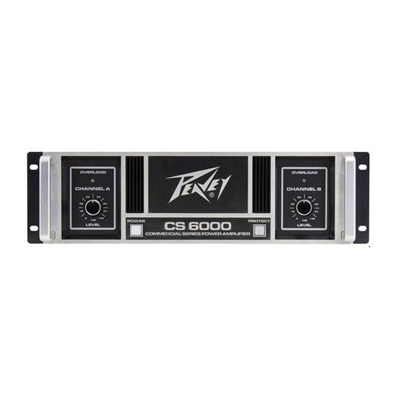
6000 and CS
Power Amplifiers
OVERLOAD
CHANNEL B
20
23
16
26
6
29
0
+32
(dB)
LEVEL
OVERLOAD
CHANNEL B
CHANNEL A
20
23
LINE OUTS
INPUTS
40 Hz
16
26
THRU
150 Hz
6
29
X-OVER
0
+32
+
(dB)
HIGH
LOW
OUT
OUT
A
LEVEL
-
GND
-
B
40 Hz
+
THRU
150 Hz
X-OVER
TM
HIGH
LOW
OUT
OUT
CHANNEL B
www.peavey.com
CHANNEL A
LINE OUTS
INPUTS
40 Hz
THRU
®
4000
Operating
Manual
Advertisement
Table of Contents

Related Manuals for Peavey CS 6000


Summary of Contents for Peavey CS 6000
-
Page 1: Power Amplifiers
® ® 6000 and CS 4000 Power Amplifiers Operating Manual OVERLOAD OVERLOAD CHANNEL A CHANNEL B (dB) (dB) CS 6000 LEVEL LEVEL OVERLOAD OVERLOAD CHANNEL A CHANNEL B CHANNEL A CHANNEL B BRIDGE CHANNEL A LINE OUTS INPUTS 40 Hz... - Page 2 Power Amplifier Congratulations on your purchase of the CS 6000/ CS 4000, a power amplifier designed for years of reliable, flawless operation under rigorous use. This amplifier offers the sonic superiority and unsurpassed reliability for which Peavey is famous, while remaining sur- prisingly compact.
- Page 3 Service Information amplifier output. Never hold a power switch or circuit Peavey is not responsible for damage breaker in the "ON" position if it Do not remove the cover! to loudspeakers for any reason.
-
Page 4: Installation
Installation Cooling Requirements Unpacking Connecting Power The CS 6000/ CS 4000 amplifier uses a Upon unpacking, inspect the ampli- The CS 6000/ CS 4000 amplifier power forced-air cooling system to maintain fier. If you find any damage, notify requirements are rated at 1/8 power a low, consistent operating tempera- your supplier immediately. -
Page 5: Ac Power Switch
LEVEL AC POWER SWITCH(1) Pressing the CS 6000/ CS 4000 power switch will alternately turn the amplifier on or off. Once the amplifier has completed its power on sequence, the switch will light indicating it is on and operational. CHANNEL A... -
Page 6: Ac Power Inlet
Primary Circuit Breakers (8) The CS 6000/ CS 4000 has separate power supplies for each channel each protected from overload with its own circuit breaker. Efforts should be made to correct the cause of the overload, first by disconnecting one output at a time, and then one speaker at a time until the bad cable or damaged speaker is isolated. -
Page 7: Connecting Outputs
When a 2-channel amplifier is operated in the Bridge mode, it is converted into a single-channel unit with a power rating equal to the sum of the power rating for each channel, at a load of twice that of the single-channel rating. For example, the CS 6000 is rated at 2900 Watts per channel into 2 Ohms. -
Page 8: Operation Modes
Operation Modes Stereo Operation For stereo (dual channel) operation, turn the amplifier off and set the mode select switches on the back panel to the OUT (extended) position. In this mode, both channels operate independently of each other with their input attenuators controlling their respective levels. -
Page 9: Protection Features
The CS 6000/ CS 4000 amplifier incorporates several circuits to protect both themselves and loudspeakers under vir- tually any situation. Peavey has attempted to make the amplifiers as foolproof as possible by making them immune to short and open circuits, mismatched loads, DC voltage, and overheating. If a channel goes into the Distortion Detection Technique or DDT™... -
Page 10: Turn-On/Turn-Off Protection
Protection Features Turn-On/Turn-Off Protection At power-up, the amplifier stays in mute mode with outputs disconnected for several seconds while the power supplies charge and stabilize. When power is removed, the mute mode engages so that no thumps or pops are heard. -
Page 11: Speaker Protection
A CS 6000/ CS 4000 amplifier requires no routine maintenance and should never need any internal adjustment during its lifetime. Your CS 6000/ CS 4000 amplifier is very powerful and can be potentially dangerous to loudspeakers and humans alike. It is your responsibility to read the Important Precautions section in the front of this manual and to make sure that the amplifier is installed, wired and operated properly. - Page 12 CS®6000/CS®4000 Specifications CS 6000 CS 4000 Rated Power Bridge 4 Ohms @1kHz 0.15% THD 5800 Watts 3600 Watts Rated Power Bridge 8 Ohms @1kHz 0.15% THD 4300 Watts 2800 Watts Rated Power 2 Ohms @1kHz 0.15% THD Both channels driven...
- Page 13 Electrical Construction: Dual power supplies Dimensions: 5.25"x 19"x 17" (13.3x 48.3x 43.2 cm) HxWxD behind panel. Handle 1.6" 4.1 cm Net Weight: CS 6000- 32.2 kg (70.8 lbs) CS 4000- 30.3 kg (67 lbs) Gross Weight: CS 6000- 38.0 kg (83.8 lbs) CS 4000- 35.8 kg (80 lbs)
- Page 14 Warranty registration and information for U.S. customers available online at www.peavey.com/warranty or use the QR tag below Features and speci cations subject to change without notice. Peavey Electronics Corporation 5022 Hartley Peavey Drive Meridian, MS 39305 (601) 483-5365 FAX (601) 486-1278 Logo referenced in Directive 2002/96/EC Annex IV (OJ(L)37/38,13.02.03 and defined in EN 50419: 2005...