
Related Manuals for Honeywell NetAXS NX4L1


Summary of Contents for Honeywell NetAXS NX4L1
- Page 1 Honeywell NetAXS™ NX4L1 Access Control Unit Installation Guide July 2016 © 2016 Honeywell. All rights reserved. 7-901099V3...
- Page 2 Ordering Information Please contact your local Honeywell representative or visit us on the web at www.honeywellaccess.com for information about ordering. Feedback Honeywell appreciates your comments about this manual. Please visit us on the web at www.honeywellaccess.com to post your comments.
-
Page 3: Table Of Contents
ABLE OF ONTENTS NetAXS™ NX4L1 Installation Guide 1.0 Notices ..............................1.1 Warnings and Cautions ....................11 1.2 Product Liability, Mutual Indemnification ..............12 1.3 Limited Warranty......................12 1.4 Federal Communications Commission ................13 1.5 Industry Canada ....................... 13 1.6 Underwriters Laboratories Incorporated................14 2.0 Introduction ............................ - Page 4 7.6 Environment........................61 7.7 Communications and Wiring ................... 61 7.8 Reader Wiring........................62 7.9 NX4L1 Panel Wiring Diagram ..................63 8.0 Maintenance ............................9.0 Troubleshooting ..........................10.0 Technical Support ........................... 10.1 Normal Support Hours....................66 10.2 Web ..........................66 www.honeywell.com...
- Page 5 NetAXS™ Standalone Operation 1.0 Basic Standalone Operations ......................1.1 Card Read / Door Lock Operation................... 67 1.2 Door Egress / Door Lock / Door Status Operation ............67 2.0 Standalone Settings ........................... 2.1 NetAXS Panel Hardware Settings ................... 68 2.2 Communication Settings....................68 2.3 Emulation Settings......................
- Page 6 www.honeywell.com...
- Page 7 IST OF IGURES Figure 1: NX4L1 Panel Components ..................17 Figure 2: Tying the Field Wiring in the NX4L1 Cabinet ............22 Figure 3: NetAXS Panel Cabinet, Back View ................. 23 Figure 4: NetAXS Panel Cabinet, Top View ................24 Figure 5: NetAXS Panel Cabinet, Bottom View ..............
- Page 8 Figure B-1: Twisted Pair ......................79 Figure B-2: RS-485 Wiring for NetAXS-4 Loop ..............81 Figure B-3: RS-485 Wiring for a Mixed Loop ................. 82 www.honeywell.com...
- Page 9 IST OF ABLES Table 1 Cabinet Electrical Entries ..................... 27 Table 2 Reader Wiring ......................27 Table 3 Default Supervised Input Assignments ................ 28 Table 5 DIP Switch Settings ..................... 38 Table 6 NX4IN DIP Switch and Jumper Settings ..............39 Table 7 LED Status ........................
- Page 10 www.honeywell.com...
-
Page 11: Netaxs™ Nx4L1 Installation Guide
Verbal approvals are not valid. WARNING Honeywell never recommends using WIN-PAK or related products for use as a primary warning or monitoring system. Primary warning or monitoring systems should always meet local fire and safety code requirements. The installer must also test the system on a regular basis by instructing the end user in appropriate daily testing procedures. -
Page 12: Product Liability, Mutual Indemnification
Customer harmless for any costs or damages including reasonable attorneys’ fees which the Customer may be required to pay as a result of the defective Product or the negligence of Honeywell, its agents or its employees. -
Page 13: Federal Communications Commission
DISTRIBUTOR SHALL EXTEND THE LIABILITY OR RESPONSIBILITY OF THE MANUFACTURER BEYOND THE TERMS OF THIS PROVISION. IN NO EVENT SHALL HONEYWELL BE LIABLE FOR ANY RE-PROCUREMENT COSTS, LOSS OF PROFITS, LOSS OF USE, INCIDENTAL, CONSEQUENTIAL OR SPECIAL DAMAGES TO ANY PERSON RESULTING FROM THE USE OF HONEYWELL PRODUCTS. -
Page 14: Underwriters Laboratories Incorporated
The input points only monitor the door position. The NetAXS panel is not intended as a Proprietary Alarm Unit - Category APOU, UL1076 standard. The NetAXS panel was approved using the following Honeywell readers: OmniAssure™ OT30, OmniClass™ OM40 and OM55, and OmniProx™ OP30 and OP40. - Page 15 NetAXS™ NX4L1 Installation Guide Notices • The model NX4L1 control units are compatible with the following Listed reader heads: • Honeywell OmniAssure™ OT30 • Honeywell OmniClass™ OM40 • Honeywell OmniClass™ OM55 • Honeywell OmniProx™ OP30 • Honeywell OmniProx™ OP40 NetAXS™ NX4L1 Access Control Unit Installation Guide, Document 7-901099V3...
-
Page 16: Introduction
NetAXS system configurations. A NetAXS access control system is configured and maintained via either the host system or a web server using RS-232, RS-485, or Ethernet network protocols. This document describes how to install and configure the NX4L1 access control unit. www.honeywell.com... -
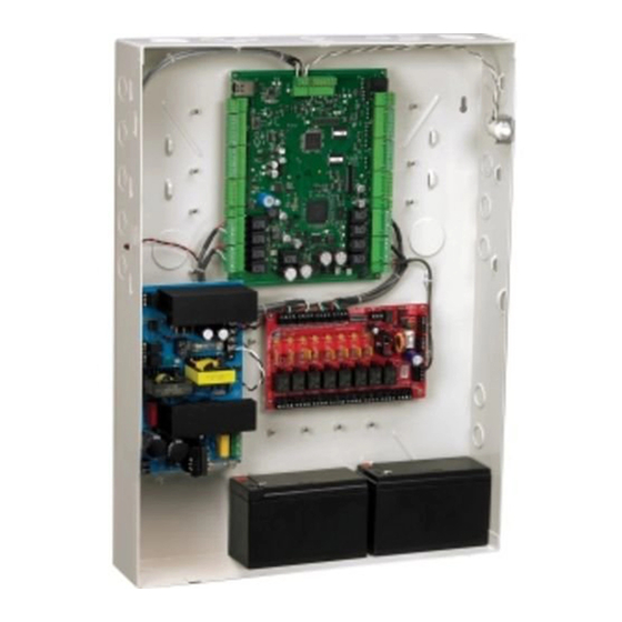
Page 17: Panel Components And Descriptions
NetAXS™ NX4L1 Installation Guide Panel Components and Descriptions 3.0 Panel Components and Descriptions The NX4L1 access control unit consists of a NetAXS panel control board, a power distribution module, a power supply, and batteries. The components are enclosed in a pre-wired cabinet. -
Page 18: Netaxs Access Control Unit
600 mA: Reader 1 + Reader 2 + Reader 3 + Reader 4 + AUX Power < 600 mA. Maximum combined current of the two auxiliary outputs (if used without the four reader outputs) is 500 mA. CAUTION AUX Power must not be used to power locks. For NetAXS maximum current draw, refer to panel specifications. www.honeywell.com... -
Page 19: Power Supply
3.3 Batteries For the NX4L1, two 12 VDC, 7 Ah sealed lead-acid batteries (Honeywell order number 3-000066) wired in series must be used to have backup battery capability. The batteries will provide standby backup power, depending upon system configuration and activity. -
Page 20: Installation
J37 for communication termination and biasing (see “System Configuration“ on page 42 and “Jumper Settings“ on page 39). 8. Check all wiring at this time. CAUTION Improper wiring can cause damage to the NetAXS at power up and result in a loss of warranty. www.honeywell.com... -
Page 21: Installing The Optional Ac Inlet
5. Plug the AC inlet unit’s power cord into the three-prong receptacle. 6. Plug the other end of the cable into a standard non-switched 115 VAC outlet. Use only a Honeywell-provided power cord (HAS part number 700-0109). UL has evaluated the Note: use of this power cord with the optional AC inlet for the NX4L1. -
Page 22: Typing The Field Wiring In The Nx4L1 Cabinet
Wiring shown as |||||||||||||||||||||||||||| Class 2 power-limited field represent shrink wrap barrier wiring to maintain a protection (0.028 inch thickness minimum of 0.25 inch minimum) where spacing between spacing from non-power-limited and power-limited non-power-limited wiring wiring is less than 0.25 inches. www.honeywell.com... -
Page 23: Cabinet Mounting
NetAXS™ NX4L1 Installation Guide Installation 4.3 Cabinet Mounting The following five figures show the back, top, bottom, right, and left views of the NetAXS panel cabinet. Each view includes the dimensions and knockout placement that you will need to mount the cabinet. -
Page 24: Figure 4: Netaxs Panel Cabinet, Top View
NetAXS™ NX4L1 Installation Guide Installation Figure 4: NetAXS Panel Cabinet, Top View 1 5/8" (41 mm) 31/32" (25 mm) Figure 5: NetAXS Panel Cabinet, Bottom View 31/32" (25 mm) 1 5/8" (41 mm) www.honeywell.com... -
Page 25: Figure 6: Netaxs Panel Cabinet, Left View
NetAXS™ NX4L1 Installation Guide Installation Figure 6: NetAXS Panel Cabinet, Left View 2 9/16" (65 mm) 4 23/32" (120 mm) 6 11/16" (170 mm) 8 21/32" (220 mm) 10 10/16" (270 mm) 16 30/32" (430 mm) 18 29/32" (480 mm) 22 3/8"... -
Page 26: Figure 7: Netaxs Panel Cabinet, Right View
6 11/16" (170 mm) 8 21/32" (220 mm) 10 10/16" (270 mm) 15 3/4" (400 mm) 17 3/16" (436.87" mm) 17 23/32" (450 mm) 13/16" (21 mm) 20 1/8" (511.5 mm) 20 11/32" (517 mm) 20 15/16" (532 mm) 22 3/8" (568mm) www.honeywell.com... -
Page 27: Reader Wiring
NetAXS™ NX4L1 Installation Guide Installation Table 1 lists the dimensions of the cabinet’s conduit entries. Table 1 Cabinet Electrical Entries ENCLOSURE CONDUIT CONDUIT CONDUIT 1” CONDUIT 2” 1/2” (12.7 mm) 3/4” (19.0 mm) (25.4 mm) (50.8 mm) Bottom Right Side Left Side Back 4.4 Reader Wiring... -
Page 28: Supervised Input Wiring
The following figure shows the typical wiring for a supervised input. Figure 8: Typical Supervised Input Wiring Diagram 2.2K 2.2K DOOR 1 EGRESS COMMON DOOR 1 STATUS 2.2K DOOR 2 EGRESS COMMON 2.2K DOOR 2 STATUS www.honeywell.com... -
Page 29: Nx4L1 Control Output Wiring
NetAXS™ NX4L1 Installation Guide Installation The figure above shows standard 2,200 ohm resistors. The NetAXS panel accepts 1,000, 2,200, 4,700, or 10,000 ohm values. Note that both resistors must have the same value. See the NetAXS™ Access Control Unit User’s Guide for instructions on selecting resistor options. - Page 30 +24 VDC is off or if the over current protection circuit is active. The FACP relay output will de-energize if the external FACP input is active. Either one of these outputs can be optionally wired into the supervised inputs on the NetAXS panel and configured as two-state inputs. www.honeywell.com...
-
Page 31: Figure 9: Power Distribution Board Field Wiring
NetAXS™ NX4L1 Installation Guide Installation The following figure shows the power distribution board field wiring. Figure 9: Power Distribution Board Field Wiring NX4L1 NetAXS ENCLOSURE Circuit Board 1 NC 5 NO 1 COM 5 COM 1 NO 5 NC 2 NC 6 NO FIELD WIRING 2 COM... -
Page 32: Communications
Figure 11, RS-232 Configuration. Figure 10 illustrates the connections for an RS-232, DB9 (9 pin) connector to the panel’s RJ-45 serial port. Replacement cables can be obtained by contacting your Honeywell Access System Representative. Figure 10: RJ-45 Serial Port www.honeywell.com... -
Page 33: Figure 11: Rs-232 Configuration
NetAXS™ NX4L1 Installation Guide Installation Figure 11: RS-232 Configuration Reader 1 NetAXS COM1 Panel Reader 4 CBL50 Terminal Reader 1 NetAXS COM2 Panel Reader 4 One NetAXS panel per COM port. Two COM ports possible. RS-485 Communications The NetAXS panel can reside on an existing RS-485 drop line hosted by either a NetAXS panel configured as a Gateway, or N-485-PCI-2, PCI-3, or N-485-HUB-2 (see Figure... -
Page 34: Figure 12: Rs-485 Configuration Via N-485-Pci-2 Or Pci-3
31 panels per multidrop line Figure 13: RS-485 Configuration via NetAXS Gateway COM1 NetAXS Gateway Terminal RS-485 Multidrop Line NetAXS NS2+ NetAXS A combination of NetAXS and NS2+ panels, supporting a total of 31 panels per multidrop line www.honeywell.com... -
Page 35: Figure 14: Ethernet Tcp/Ip Configuration
NetAXS™ NX4L1 Installation Guide Installation Ethernet TCP/IP Communications Figure 14: Ethernet TCP/IP Configuration Network Interface Ethernet Card Inside PC Up to 255 TCP/IP Connections per System Ethernet Terminal 10/100 NetAXS Gateway RS-485 Multidrop Line NetAXS NS2+ NetAXS A combination of NetAXS and NS2+ panels, supporting a total of 31 panels per multidrop line Each NetAXS panel has a port for an Ethernet TCP/IP interface (see Figure 14,... -
Page 36: Figure 15: Ethernet Mac Address Location
NetAXS™ NX4L1 Installation Guide Installation Figure 15 shows the location of the panel’s unique MAC ID. Figure 15: Ethernet MAC Address Location Label with Ethernet MAC Address www.honeywell.com... -
Page 37: Dip Switch Settings
NetAXS™ NX4L1 Installation Guide Installation 4.8 DIP Switch Settings Figure 16 locates the NX4L1 DIP switch panel and the J36 and J37 jumpers. Figure 16: DIP Switch and Jumper Location Switches NetAXS™ NX4L1 Access Control Unit Installation Guide, Document 7-901099V3... -
Page 38: Table 5 Dip Switch Settings
Address 18 Address 19 Address 20 Address 21 Address 22 Address 23 Address 24 Address 25 Address 26 Address 27 Address 28 Address 29 Address 30 Address 31 NetAXS Multidrop NetAXS Gateway Address 0 is not a valid setting. Note: www.honeywell.com... -
Page 39: Jumper Settings
NetAXS™ NX4L1 Installation Guide Installation 4.9 Jumper Settings The NX4L1 panel control board includes jumpers 36 and 37, which set end-of-line termination and biasing for the Multidrop RS-485 Line. The board ships with all jumpers set to OFF. For a Multidrop RS-485 Line, you must set both J36 and J37 to CLOSED (terminated and biased) at the two end-point panels. - Page 40 I/O. A separate 24 VDC supply should be used to provide power to all downstream modules and output loads. For some installations, the noise immunity improves if the NetAXS common is connected to the 24 V Return wiring for the downstream modules. This connection is not needed for most installations. www.honeywell.com...
-
Page 41: Figure 17: Default Downstream I/O Configuration With Wiring
NetAXS™ NX4L1 Installation Guide Installation The following figure shows the default downstream I/O system configuration with communication and power wiring. Figure 17: Default Downstream I/O Configuration with Wiring RS-485 A RS-485 A TB10-3 TB3-2 TB3-7 RS-485 B RS-485 B NX4IN TB3-3 TB3-8 TB10-2... -
Page 42: System Configuration
S1-S5 Panel Address S6: OFF S6: OFF J36 CLOSED J36 OPEN J37 CLOSED J37 OPEN NetAXS NetAXS It is recommended to Earth Ground (EG) each Panel Panel NetAXS enclosure individually Only Earth Ground (EG) d (EG) one side of cable www.honeywell.com... -
Page 43: Rs-485 Connection Via Netaxs
NetAXS™ NX4L1 Installation Guide System Configuration 5.2 RS-485 Connection via NetAXS This connection supports thirty-one NetAXS Access Controller panels for each drop line. However, because UL has approved the NetAXS panel only as a standalone system, the computer terminal and NetAXS gateway panel appear in this illustration only to show the installation and programming of the NetAXS panel. -
Page 44: Rs-485 Connections With Multidrop Panels At Both Ends Of The Cable
J37 CLOSED J37 OPEN NetAXS NetAXS NetAXS NetAXS Panel Panel Panel Panel Only Earth Ground (EG) Only Earth Ground (EG) one side of cable one side of cable It is recommended to Earth Ground (EG) each NetAXS enclosure individual www.honeywell.com... -
Page 45: Figure 21: Rs-485 Connection Via Pci-2 With Multidrop Panels At Both Ends
NetAXS™ NX4L1 Installation Guide System Configuration Figure 21: RS-485 Connection via PCI-2 with Multidrop Panels at Both Ends RS-232 (50 ft. max.) COM Port RS-485 (4,000 ft.) N-485-PCI- Host Refer to N-485-PCI-2/NetAXS Access Controller Panel Connection Detail diagram DIP Switch Settings RS-485 Cable S1: ON S2: ON... -
Page 46: Rs-232 Connection
It is recommended to Earth Ground (EG) each NetAXS enclosure individually CBL50 (RS-232) RS-232 RJ-45 (DB9) Request To Send (RTS) Signal Ground (GND) Receive Data (RXD) Transmit Data (TXD) Clear To Send (CTS) 9-Pin COM 1 or COM 2 to RJ-45 on NetAXS Panel www.honeywell.com... -
Page 47: Ethernet Connection
NetAXS™ NX4L1 Installation Guide System Configuration 5.5 Ethernet Connection This connection supports a maximum of 255 IP connections per server. It has not been approved by UL. Figure 23: Ethernet Connection 100BaseT (CAT5) 328 ft. max. HUB/SWITC Terminal HUB/SWITCH HUB/SWITCH RS-485 Multidrop NetAXS 100BaseT (CAT5) -
Page 48: Lansrlu1 Connection
J36: CLOSED J36: OPEN NetAXS Panel J37: CLOSED J37: OPEN Connection Detail diagram NetAXS NetAXS Panel Panel See RS-485 Cable Note It is recommended to Earth Ground (EG) each NetAXS enclosure individually Only Earth Ground (EG) one side of cable www.honeywell.com... -
Page 49: Rs-485 Short Haul Modem Connection Via Pci-2
NetAXS™ NX4L1 Installation Guide System Configuration 5.7 RS-485 Short Haul Modem Connection via PCI-2 This connection supports 31 NetAXS Access Controller panels for each drop line. It has not been approved by UL. Figure 25: RS-485 Short Haul Modem Connection via PCI-2 RS232 Cable MODEM (DB-9) -
Page 50: Rs-485 Short Haul Modem Connection Via Netaxs
(Straight) (Null) S1-S5 Panel Address NetAXS CBL50 S6: ON Male 9 Pin Male 25 Pin 2 TX 2 (TX) 2 (RX) Panel J36: CLOSED 3 RX 3 (RX) or 3 (TX) J37: CLOSED 5 Comm 7 (GND) 7 (GND) www.honeywell.com... -
Page 51: Rs-232 Short Haul Modem Connection
NetAXS™ NX4L1 Installation Guide System Configuration 5.9 RS-232 Short Haul Modem Connection This connection supports one NetAXS Access Controller panel for each loop. It has not been approved by UL. Figure 27: RS-232 Short Haul Modem Connection RS232 Cable MODEM (DB-9) (Straight) (Null) -
Page 52: M-56K Dial-Up Modem, Rs-485 Connection Via Hub
RS-485 Cable DB 9 / DB 25 Connectors NetAXS Panels Female Male TB7-1 (RS485+) TB7-2 (RS485-) TB7-3 (RS485 COM) 4,000 ft. (1,200 m) max, 24 AWG, 2 twisted pairs with shield, 120 ohm, 23 pf (HAS part no. NCP2441-TN) www.honeywell.com... -
Page 53: M-56K Dial-Up Modem, Rs-485 Connection Via Netaxs
NetAXS™ NX4L1 Installation Guide System Configuration 5.11 M-56K Dial-up Modem, RS-485 Connection via NetAXS This connection supports 31 NetAXS Access Controller panels for each drop line. It has not been approved by UL. Figure 29: M-56K Dial-up Modem, RS-485 Connection via NetAXS M-56K FAX/MODEM COM Port... -
Page 54: Fiber Converter To Rs-485 Connection Via Pci-2
TB7-2 (RS485-) RS-485 COM TB7-3 (RS485 COM) DIP Switch Settings S1-S5 Panel Address 4,000 ft. (1,200 m) max, 24 AWG, 2 twisted pairs with S6: OFF shield, 120 ohm, 23 pf (HAS part no. NCP2441-TN) J36: OPEN J37: OPEN www.honeywell.com... -
Page 55: Fiber Converter To Rs-485 Connection Via Netaxs
NetAXS™ NX4L1 Installation Guide System Configuration 5.13 Fiber Converter to RS-485 Connection via NetAXS This connection supports 31 NetAXS Access Controller panels for each drop line. It has not been approved by UL. Figure 31: Fiber Converter to RS-485 Connection via NetAXS RS-485 (4000 ft. -
Page 56: N-485-Pci-2/Netaxs Access Controller Panel Connection Detail
J36: OPEN J37: CLOSED J37: OPEN Ground only one side of cable shield Shield Common 485 + 485 - 4,000 ft. (1,200 m) max, 24 AWG, 2 twisted pairs with shield, 120 ohm, 23 pf (HAS part no. NCP2441-TN) www.honeywell.com... -
Page 57: Netaxs/Netaxs Access Controller Panel Connection Detail
NetAXS™ NX4L1 Installation Guide System Configuration 5.15 NetAXS/NetAXS Access Controller Panel Connection Detail Figure 33: NetAXS/NetAXS Access Controller Panel Connection Detail Ground Shield DO NOT CONNECT or GROUND SHIELD To Serial Connection NetAXS TB7 NetAXS TB7 DIP Switch Settings DIP Switch Settings S1-S5: Panel Address S1-S5: Panel Address DIP Switch Settings... -
Page 58: Netaxs Startup
Table 7 on page 59. Figure 34: System, Relay and Power LEDs (Ethernet) LINK (Readers) (Host RS232 H485 Downstream) H232 (Host RS485) RDR 1 (Readers) RDR 2 (Relays) (Relays) (Power) www.honeywell.com... -
Page 59: Table 7 Led Status
NetAXS™ NX4L1 Installation Guide NetAXS Startup The following table indicates the status associated with each LED. Table 7 LED Status H485 H232 LINK GREEN Power Multi- RS232 Down- 100Mbit Link Relay Flash at Heart drop Receive stream Active read Beat Receive Data Receive... -
Page 60: Hardware Specifications
Enclosure Dimension: 17.7 in. (450 mm) W × 23.9 in. (607 mm) H × 3.54 in. (90 mm) D. • Enclosure Weight: • With two batteries (including the door): 33.70 lb. • With one battery (including the door): 28.90 lb. • Without batteries (including the door): 24.25 lb. www.honeywell.com... -
Page 61: Environment
NetAXS™ NX4L1 Installation Guide Hardware Specifications 7.6 Environment • Temperature: 0°C to 49°C operating, –55°C to +85°C storage. • Humidity: UL approved at 85%, non-condensing. 7.7 Communications and Wiring Table 8 Communications and Wiring Maximum Maximum Distance: Communication Type Description Panels Feet (Meters) Direct to COM Port... -
Page 62: Reader Wiring
Hardware Specifications 7.8 Reader Wiring Table 9 Reader Wiring Cable Specifications Description Maximum Distance: Feet (Meters) Readers NC1861-BL 6 Conductor, Shielded 500 (153) Alarm Input NC1821-GR Twisted Pair, Shielded 2,000 (610) Relay Outputs NC1821-GR Twisted Pair, Shielded 2,000 (610) www.honeywell.com... -
Page 63: Nx4L1 Panel Wiring Diagram
Optional CASIL CA1270 CASIL CA1270 Green AC Inlet* HAS 3-000066 HAS 3-000066 Honeywell P/N Brown 100-00049 12 VDC, 7 Ah 12 VDC, 7 Ah * Represents field wiring (Class 2 power-limited) NetAXS™ NX4L1 Access Control Unit Installation Guide, Document 7-901099V3... -
Page 64: Maintenance
3. Replace the blown fuse in the lower section of the fuse holder with the new fuse. The upper section of the fuse holder provides a convenient location for a spare fuse. 4. Slide the fuse holder back into the power inlet terminal block. 5. Re-connect the AC power. www.honeywell.com... -
Page 65: Troubleshooting
NetAXS™ NX4L1 Installation Guide Troubleshooting 9.0 Troubleshooting Table 10 Troubleshooting Problems and Solutions Problem Solution The panel Ensure that the Address DIP switches are set to a value other than zero. powers up, but it Turn off the power (including battery), change the settings, and re-apply does not respond the power. -
Page 66: Technical Support
RS-485 positive and negative terminals if the EOL network is on or off (J36 and J37). 10.0 Technical Support 10.1 Normal Support Hours Monday through Friday, 7:00 a.m. to 7:00 p.m. Central Standard Time (CST), except company holidays: 1-800-323-4576. 10.2 Web For technical assistance, please visit http://www.honeywellaccess.com www.honeywell.com... -
Page 67: Netaxs™ Standalone Operation
NetAXS™ Standalone Operation 1.0 Basic Standalone Operations 1.1 Card Read / Door Lock Operation 1. Present a card to a reader. 2. The reader sends the card number to a reader input on the panel. 3. The panel searches its database and: •... -
Page 68: Standalone Settings
• Echo typed characters locally: YES • Line Delay: 500 milliseconds 2.4 Verifying Communications 1. Press the spacebar. 2. Press the carriage return <CR>. “S?” appear for every online panel and indicates proper communication between the terminal and panel. www.honeywell.com... -
Page 69: Standalone Commands
NetAXS™ Standalone Operation Standalone Commands 3.0 Standalone Commands CAUTION Use the following commands, in the order they are listed, to configure the NetAXS™ panel. 1. T command: Sets the panel’s time 2. D command: Sets the panel’s date 3. L command: Creates time zones for use by the cards 4. -
Page 70: D (Date) Command
This command would set panel 1 to a date of 1/9/2007 and to Tuesday as the day of the week. Example 2 _D=25_12/14/2009_7<CR> This command would set panel 25 to a date of 12/14/2009 with a day of week being Monday. www.honeywell.com... -
Page 71: L (Time Zone) Command
NetAXS™ Standalone Operation Standalone Commands 3.3 L (Time Zone) Command _L=pn_tz_h1:m1-h2:m2_days<CR> Variables: pn = panel number (1–31) tz = time zone number (1–255) h1 = start time zone: hours (00–23) (Military time) m1 = start time zone: minutes (00–59) h2 = end time zone: hours (00–23) (Military time) m2 = end time zone: minutes (00–59) days = days of week valid values as listed below: 1 = Monday... -
Page 72: C (Card Add) Command
Variables: pn = panel number (1–31) code = card number (range depends on card format) Example 1 _C=6_12345<CR> This command would remove card 12345 from panel 6. Example 2 _C=18_52989<CR> This command would remove card 52989 from panel 18. www.honeywell.com... -
Page 73: W (Input) Command
NetAXS™ Standalone Operation Standalone Commands 3.6 W (Input) Command _W=pn_input_{SO|SC|NO|NC}<CR> Variables: SO: Supervised normally open SC: Supervised normally closed NO: Non-supervised normally open NC: Non-supervised normally closed (default) Example _W=1_9_SO<CR> Input 9 has been programmed as supervised, normally open on panel 1. 3.7 P (Interlock) Command _P=pn_I/O_[number]_I/O[number]_{D|E|F|N|P}_ {D|E|F|N|P}<CR>... -
Page 74: Flow Control Disable/Enable Command
(Use this command only for a drop line panel using RS-232 in standalone mode) _U=[panel name]_{D|E} Parameters: D: Disable E: Enable Example _U=30_D This disables the flow control on panel 30 and prevents the panel’s buffers from filling. After a hard reset of the panel, the flow control is re-enabled. www.honeywell.com... -
Page 75: Netaxs Panel Defaults
NetAXS™ Standalone Operation NetAXS Panel Defaults 4.0 NetAXS Panel Defaults 4.1 Reader Ports The panel accepts a Wiegand serial data packet from the card reader. If the card is in the database, the associated relay is activated. If the card is not in the database, the relay state is unchanged. -
Page 76: Reader Tamper Inputs
Normally Closed contact. When the egress input is active, the associated output relay will be active. The following are the default egress input associations: Egress input Controls relay... Panel input Reports as... Input 1 Input 3 Input 5 Input 7 www.honeywell.com... -
Page 77: Door Status Inputs
NetAXS™ Standalone Operation NetAXS Panel Defaults 4.5 Door Status Inputs The panel has a Door Status input for each door. The default condition is a two-state input configured as a Normally Closed contact. The following are the default door status input associations: Door Status input Panel input Reports as... -
Page 78: Additional Generic Outputs
NetAXS™ Standalone Operation NetAXS Panel Defaults 4.7 Additional Generic Outputs The panel has the following four additional generic form C relay outputs that can be programmed using the P command: Relay output Controls... Output 5 Output 6 Output 7 Output 8 www.honeywell.com... -
Page 79: Recommended Wiring For Netaxs-4/Netaxs-123 Loops
Recommended Wiring for NetAXS-4/NetAXS-123 Loops 1.0 Overview This document provides the recommended RS-485 wiring for NetAXS-4 and mixed loop configurations. The downstream controller boards communicate to the gateway controller board through an RS-485 interface. The interface allows for multidrop communication of up to 4,000 feet (1,200 m) total per port. -
Page 80: The Shield Wire
On a loop that contains all NetAXS-4 controllers, the 485 COM is connected. The second pair of the wires are twisted together and connected to 485 COM on the controller. • The shield is only connected on one end of the cable, not both. See Figure B-2 on page 81. www.honeywell.com... -
Page 81: Rs-485 Wiring For A Mixed Loop
RS-485 Wiring for a Mixed Loop Figure B-2: RS-485 Wiring for NetAXS-4 Loop Ground Shield DO NOT CONNECT or GROUND SHIELD To Serial Connection NetAXS TB7 NetAXS TB7 DIP Switch Settings DIP Switch Settings S1-S5: Panel Address S1-S5: Panel Address DIP Switch Settings S6: OFF S6: OFF... - Page 82 485– respectively. The second pair (usually green and white) are twisted together and connected to COM with the exception of the NetAXS-123 controller where the common is bypassed. In the above figure, the white wire is colored purple for easy viewing. Note: www.honeywell.com...
-
Page 83: End Of Line Termination
End of Line Termination 5.0 End of Line Termination By default, the controllers are not terminated. If the controller is the last one on the 485 bus then it should be terminated. For more information, see the controller’s installation guide. •... - Page 84 End of Line Termination www.honeywell.com...
- Page 86 Honeywell Access Systems 135 W. Forest Hill Avenue, Oak Creek, WI 53154 1-800-323-4576 www.honeywellaccess.com Document 7-901099V3 © Honeywell International Inc. All rights reserved. Specifications subject to change without notice.