Honeywell 705 Operating Instructions Manual
Combustible gas sensor ul certified
Hide thumbs
Also See for 705:
- Operating instructions manual (27 pages) ,
- Operating instructions manual (27 pages) ,
- Calibration handbook (164 pages)
Table of Contents
Advertisement
Advertisement
Table of Contents

Related Manuals for Honeywell 705


Summary of Contents for Honeywell 705
- Page 1 Operating Instructions Sensors Type 705 Combustible Gas Sensor Ul Certified...
-
Page 2: Man0363.Pm6 Issue 02, Aug
MAN0363.PM6 Issue 02, Aug 97 705 Sensor 00705M5002 HELPING TO MAKE A SAFER WORLD Ensure that you read and understand these operating instructions BEFORE installing or operating any part of the equipment. Please pay particular attention to the Safety Warnings. - Page 3 MAN0363.PM6 Issue 02, Aug 97 705 Sensor 00705M5002 HELPING TO MAKE A SAFER WORLD IMPORTANT NOTICES Zellweger Analytics Limited can take no responsibility for installation and/or use of its equipment if this is not done in accordance with the appropriate issue and/or amendment of the manual.
- Page 4 MAN0363.PM6 Issue 02, Aug 97 705 Sensor 00705M5002 HELP US TO HELP YOU Marketing Communications, From: Zellweger Analytics Limited, Hatch Pond House, Address: 4 Stinsford Road, Nuffield Estate, POOLE. Dorset. BH17 0RZ. United Kingdom. +44 (0) 1202 676161 +44 (0) 1202 678011...
-
Page 5: Table Of Contents
Weather Protection Housing Sample Flow Housing Filter MAINTENANCE General Cleaning GASSING THE SENSOR Sensor witout Accessories Sensor with Collecting Cone or Weather Protection Housing Sensor with Sample Flow Housing REPLACEMENT PARTS Terminal Housings Maintenance Spares TYPE 705 SENSOR ALTERNATIVE SYSTEMS 22 SPECIFICATION... - Page 6 MAN0363.PM6 Issue 02, Aug 97 705 Sensor 00705M5002...
-
Page 7: Introduction
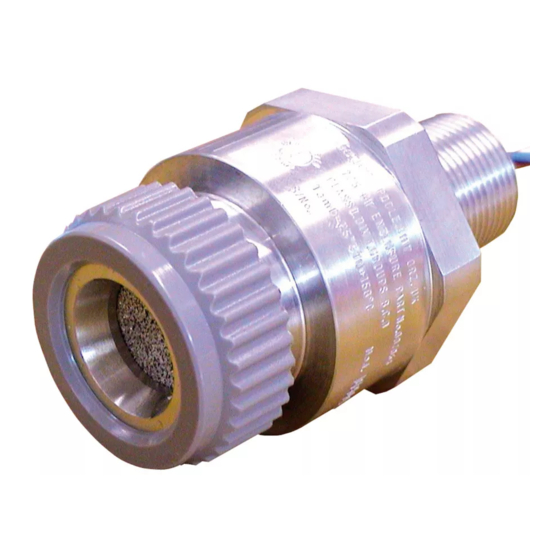
00705M5002 1. INTRODUCTION 1.1 GENERAL The 705 Sensor (Figure 1) is a combustible gas detector certified for installation in a hazardous area. This version uses the catalytic principle and in conjunction with electronic control equipment situated in a non-hazardous area it forms a combustible-gas detection system. -
Page 8: Principle Of Operation
MAN0363.PM6 Issue 02, Aug 97 705 Sensor 00705M5002 1. INTRODUCTION 1.2 PRINCIPLE OF OPERATION The Sensor contains two elements which are heated by a supply derived from the associated electronic control equipment. One element is sensitive to the presence of combustible gas, the element temperature increasing in response to catalytic oxidation of the gas. - Page 9 MAN0363.PM6 Issue 02, Aug 97 705 Sensor 00705M5002 1. INTRODUCTION A nozzle on the cone permits gassing of the Sensor with the cone in position. Test gas is applied either direct to the nozzle or via a permanently connected pipe-line when the Sensor is in an inaccessible location.
- Page 10 MAN0363.PM6 Issue 02, Aug 97 705 Sensor 00705M5002 1. INTRODUCTION 50.8mm Dia 51.0mm 25.5mm Figure 3 Weather Protection Housing 1.3.4 Sample Flow Housing A Sample Flow Housing provides a facility to allow sampling of a closed system by means of two pipelines. The flow...
- Page 11 MAN0363.PM6 Issue 02, Aug 97 705 Sensor 00705M5002 1. INTRODUCTION 1.3.5 Gassing Point Assembly The Gassing Point Assembl assembly can be fixed in a convenient position and permanently connected by suitable tubing to an inaccessible sensor, thus simplifying the application of test gas when checking sensor calibration. A...
-
Page 12: Installation
2. The type 705 Sensor must never be used in conditions where there is insufficient Oxygen to totally oxidise the combustible gas. For most combustible gases, an Oxygen level of at least 15% is sufficient. -
Page 13: Cable Connections
MAN0363.PM6 Issue 02, Aug 97 705 Sensor 00705M5002 2. INSTALLATION Cable Entry Conduit Cable Entry Conduit Adalet X1HFC3L Killark Box with Terminal Housing 705 Sensor Figure 6 Terminal Housings 2.4 CABLE CONNECTIONS The sensor is connected by three wires: Connections... -
Page 14: Fitting Sensors
Refer to Section 8 for alternative systems to which the sensor can be connected. If replacing a sensor refer to CAUTION 1 in the Maintenance section. To fit the 705 Sensor proceed as follows: Remove the protection disc and fit the accessories as required. (Refer to Section 3). - Page 15 MAN0363.PM6 Issue 02, Aug 97 705 Sensor 00705M5002 2. INSTALLATION Connect the sensor cable to the terminal block. (See label adjacent to connector). After mounting the Terminal Housing in the required location, connect the associated Control Module wiring to the terminal block (see label).
-
Page 16: Fitting Accessories
MAN0363.PM6 Issue 02, Aug 97 705 Sensor 00705M5002 3. FITTING ACCESSORIES 3.1 COLLECTING CONE (00780-A-0032) To fit the Collecting Cone Assembly to a sensor, carry out the following: Remove the Filter Housing and gasket from the sensor. Fit the Stainless Steel Filter. -
Page 17: Filter
MAN0363.PM6 Issue 02, Aug 97 705 Sensor 00705M5002 3. FITTING ACCESSORIES If required fit the Stainless Steel Filter, screw the Sample Flow Housing on to the sensor and tighten with a 40mm A/F spanner. Set the sample flow rate to 1.5 ± 0.1 litres per minute, unless otherwise directed in System installation instructions. -
Page 18: Maintenance
MAN0363.PM6 Issue 02, Aug 97 705 Sensor 00705M5002 4. MAINTENANCE 4.1 GENERAL Maintenance consists of cleaning the sensor and accessories, replacing gasket and the Hydrophobic Barrier and gassing the sensor when testing the system. CAUTIONS The sensitivity of Catalytic Sensors is impaired by silicone compounds. -
Page 19: Gassing The Sensor
MAN0363.PM6 Issue 02, Aug 97 705 Sensor 00705M5002 5. GASSING THE SENSOR 5.1 SENSOR WITHOUT ACCESSORIES Where there are no accessories fitted, it is recommended that a Sample Flow Housing is used when gassing the sensor. Where this is not possible, a suitable plastic bag may be used. - Page 20 MAN0363.PM6 Issue 02, Aug 97 705 Sensor 00705M5002 5. GASSING THE SENSOR Using the rubber tubing, connect the test gas to the flow housing input nozzle. Set the flow rate to 1.5 ± 0.1 litres per minute and test the system in accordance with the instructions in the appropriate system equipment manual.
-
Page 21: Replacement Parts
MAN0363.PM6 Issue 02, Aug 97 705 Sensor 00705M5002 6. REPLACEMENT PARTS 6.1 TERMINAL HOUSINGS Note: When ordering replacements, always quote the complete part number. Where a part number is not listed or known, state type, material, cable entry size and other relevant details. -
Page 22: Type 705 Sensor Alternative Systems
MAN0363.PM6 Issue 02, Aug 97 705 Sensor 00705M5002 7. TYPE 705 SENSOR ALTERNATIVE SYSTEMS TOXIC SYSTEMS SAFE AREA HAZARDOUS AREA CONTROL SYSTEM 5700 JUNCTION BOX 00704-A-1756 FLAMMABLE CONTROL OR A SUITABLE SENSOR CARDS UL CERTIFIED 00705-A-1732 ENCLOSURE 00705-A-1733 05700-A-0311 05700-A-0313... -
Page 23: Specification
MAN0363.PM6 Issue 02, Aug 97 705 Sensor 00705M5002 8. SPECIFICATION CERTIFICATION APPROVALS Certified for Class 1, Division 1, Groups B, C and D DRIVE CURRENT 200mA ± 2mA (From control equipment). LINE RESISTANCE Refer to Control Module Manual. MAXIMUM POWER DISSIPATION Less than 1W. - Page 24 MAN0363.PM6 Issue 02, Aug 97 705 Sensor 00705M5002 8. SPECIFICATION HUMIDITY RANGE Intermittent 0 to 100% RH non- condensing. Continuous 0 to 90% RH non-condensing. OVERALL DIMENSIONS AND WEIGHTS Sensor: Dimensions: 78mm x 55mm (47.2mm across flats). Weight: 270g. Killark HKB-BC Terminal Housing Dimensions: 155mm x 135mm x 100mm.
- Page 25 MAN0363.PM6 Issue 02, Aug 97 705 Sensor 00705M5002...
- Page 26 Tel: +41 (0)44 943 4300 Fax: +41 (0)44 943 4398 sales@zelana.co.uk Customer business center A mericas Honeywell Analytics Distribution, Inc. 400 Sawgrass Corporate Pkwy Suite 100 Sunrise, FL 33325 Tel: +1 954 514 2700 Toll free: +1 800 538 0363...