ABB ACH580-01 Hardware Manual
Hide thumbs
Also See for ACH580-01:
- Quick installation and start-up manual (412 pages) ,
- Hardware manual (398 pages) ,
- Installation, operation and maintenance manual (90 pages)

Related Manuals for ABB ACH580-01


Summary of Contents for ABB ACH580-01
- Page 1 — ABB DRIVES FOR HVAC ACH580-01 drives (0.75 to 250 kW, 1 to 350 hp) Hardware manual...
- Page 2 Related documents are listed on page 27.
- Page 3 ACH580-01 drives (0.75 to 250 kW, 1 to 350 hp) Table of contents 1. Safety instructions 4. Mechanical installation 6. Electrical installation – 7. Electrical installation – North America 2018 ABB Oy. All Rights Reserved. 3AXD50000044839 Rev B EFFECTIVE: 2018-12-20...
-
Page 5: Table Of Contents
Table of contents 5 Table of contents 1. Safety instructions Contents of this chapter ............15 Use of warnings and notes in this manual . - Page 6 6 Table of contents Frames R1 and R2 cable box (IP21, UL Type 1) ....... 60 Unpacking and examining delivery, frame R3 .
- Page 7 Table of contents 7 Separate control cable ducts, IEC and North America ......104 Implementing short-circuit and thermal overload protection ......105 Protecting the drive and input power cable in short-circuits .
- Page 8 8 Table of contents Reinstalling covers ............163 Reinstalling cover, frames R1…R4 .
- Page 9 Table of contents 9 9. Maintenance and hardware diagnostics Contents of this chapter ........... . . 225 Maintenance intervals .
- Page 10 10 Table of contents uR and aR fuses (IEC) ..........264 Circuit breakers (IEC) .
- Page 11 Table of contents 11 Frame R2, IP21 (UL Type 1) ..........313 Frame R2, IP55 (UL Type 12) .
- Page 12 12 Table of contents Competence ............352 Acceptance test reports .
- Page 13 Providing feedback on ABB Drives manuals ........
-
Page 14: Table Of Contents
14 Table of contents... -
Page 15: Safety Instructions
Safety instructions 15 Safety instructions Contents of this chapter This chapter contains the safety instructions which you must obey when you install and operate the drive and do maintenance on the drive. If you ignore the safety instructions, injury, death or damage can occur. Use of warnings and notes in this manual Warnings tell you about conditions which can cause injury or death, or damage to the equipment. -
Page 16: General Safety In Installation, Start-Up And Maintenance
16 Safety instructions General safety in installation, start-up and maintenance These instructions are for all personnel that install the drive and do maintenance work on it. WARNING! Obey these instructions. If you ignore them, injury or death, or damage to the equipment can occur. •... - Page 17 Safety instructions 17 • Before you activate the automatic fault reset or automatic restart functions of the drive control program, make sure that no dangerous situations can occur. These functions reset the drive automatically and continue operation after a fault or supply break.
-
Page 18: Electrical Safety In Installation, Start-Up And Maintenance
18 Safety instructions Electrical safety in installation, start-up and maintenance Precautions before electrical work These warnings are for all personnel who do work on the drive, motor cable or motor. WARNING! Obey these instructions. If you ignore them, injury or death, or damage to the equipment can occur. -
Page 19: Additional Instructions And Notes
Safety instructions 19 Additional instructions and notes WARNING! Obey these instructions. If you ignore them, injury or death, or damage to the equipment can occur. • A drive with the internal EMC filter connected can be installed to a symmetrically grounded TN-S system. -
Page 20: Grounding
20 Safety instructions Note: • The motor cable terminals of the drive are at a dangerous voltage when the input power is on, regardless of whether the motor is running or not. • The DC and brake resistor terminals (UDC+, UDC-, R+ and R-) are at a dangerous voltage. - Page 21 Safety instructions 21 Note: • You can use power cable shields as grounding conductors only when their conductivity is sufficient. • Standards IEC/EN 61800-5-1 (section 4.3.5.5.2.) and UL 68100-5-1 require that as the normal touch current of the drive is higher than 3.5 mA AC or 10 mA DC, you must use a fixed protective earth (PE) connection.
-
Page 22: Additional Instructions For Permanent Magnet Motor Drives
22 Safety instructions Additional instructions for permanent magnet motor drives Safety in installation, start-up and maintenance These are additional warnings concerning permanent magnet motor drives. The other safety instructions in this chapter are also valid. WARNING! Obey these instructions. If you ignore them, injury or death and damage to the equipment can occur. -
Page 23: General Safety In Operation
Safety instructions 23 General safety in operation These instructions are for all personnel that operate the drive. WARNING! Obey these instructions. If you ignore them, injury or death, or damage to the equipment can occur. • Do not power up the drive more than five times in ten minutes. Too frequent power-ups can damage the charging circuit of the DC capacitors. - Page 24 24 Safety instructions...
-
Page 25: Introduction To The Manual
Note: The manual does not apply to R0…R3 frames with type codes ACH580-01: 02A6-4, 03A3-4, 04A0-4, 05A6-4, 07A2-4, 09A-4, 12A6-4, 017A-4, 025A-4, 032A-4, 038A-4, 045A-4. For these types, see ACH580-01 (0.75 to 250 kW, 1 to 350 hp) hardware manual (3AUA0000076331[English]). -
Page 26: Contents Of This Manual
26 Introduction to the manual Contents of this manual The manual consists of the following chapters: • Safety instructions (page 15) gives safety instructions you must obey when installing, commissioning, operating and servicing the drive. • Introduction to the manual (this chapter, page 25) describes applicability, target audience, purpose and contents of this manual. -
Page 27: Categorization By Frame (Size)
Internet. Categorization by frame (size) The ACH580-01 is manufactured in frames (frame sizes) R1…R9. Some instructions and other information that only concern certain frames are marked with the symbol of the frame (R1…R9). The frame is marked on the type designation label attached to... - Page 28 +E223) installation supplement for ACS580-01, ACH580-01 and ACH580-01 frames R1 to R5 UL Type 12 hood quick installation guide for ACS580- 3AXD50000196067 01, ACH580-01 and ACQ580-01 frames R1 to R9 Tool and maintenance manuals and guides Drive composer PC tool user's manual 3AUA0000094606...
-
Page 29: Quick Installation And Commissioning Flowchart
Introduction to the manual 29 Quick installation and commissioning flowchart Task Identify the frame of your drive: R1…R9. Operation principle and hardware description: Type designation key on page Plan the installation: select the cables, etc. Guidelines for planning the electrical installation on page Check the ambient conditions, ratings and... - Page 30 30 Introduction to the manual Task Connect the control cables. Electrical installation: IEC: Connecting the control cables on page North America: Connecting the control cables on page Check the installation. Installation checklist on page Commission the drive. ACH580 HVAC control program firmware manual (3AXD50000027537 [English])
-
Page 31: Terms And Abbreviations
Introduction to the manual 31 Terms and abbreviations Term/abbreviation Explanation ACH-AP-H Assistant control panel with Hand-Off-Auto functionality for the ACH580 ACH-AP-W Assistant control panel with Hand-Off-Auto functionality and Bluetooth interface for the ACH580 Assistant control Assistant control panel (ACH-AP-x) is an advanced operator keypad for panel communication with the drive. - Page 32 32 Introduction to the manual Term/abbreviation Explanation FBIP-21 Optional BACnet/IP adapter module FCAN-01 Optional CANopen adapter module FCNA-01 ControlNet adapter module FDNA-01 Optional DeviceNet adapter module FECA-01 Optional EtherCAT adapter module FEIP-21 Optional two-port Ethernet/IP adapter module FENA-21 Optional two-port Ethernet adapter module for EtherNet/IP, Modbus TCP and PROFINET IO protocols FEPL-02 Optional Ethernet POWERLINK adapter module...
- Page 33 Introduction to the manual 33 Term/abbreviation Explanation PROFIBUS, Registered trademarks of PI - PROFIBUS & PROFINET International PROFIBUS DP, PROFINET IO Positive temperature coefficient (PTC) refers to materials that experience an increase in electrical resistance when their temperature is raised. R1, R2, …...
- Page 34 34 Introduction to the manual...
-
Page 35: Operation Principle And Hardware Description
Operation principle and hardware description 35 Operation principle and hardware description Contents of this chapter This chapter briefly describes the operation principle, layout, type designation label and type designation information. It also shows a general diagram of power connections and control interfaces. -
Page 36: Operation Principle
36 Operation principle and hardware description Operation principle The ACH580-01 is a drive for controlling asynchronous AC induction motors permanent magnet motors and synchronous reluctance motors (SynRM). The figure below shows the simplified main circuit diagram of the drive. ACH580-01... -
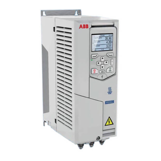
Page 37: Layout
Operation principle and hardware description 37 Layout Frames R1…R2 The layout of a frame R1 drive is presented below. The main structure of frame R2 is similar to R1. IP55 / UL Type 12 frames are also slightly different from IP21 / UL Type 1 frames, for example, IP21 / UL Type 1 front cover has two parts while IP55 / UL Type 12 front cover only has one part. - Page 38 38 Operation principle and hardware description This is an example of IP55 / UL Type 12 frames. They have one-piece front cover, which has a transparent window to leave the control panel visible. UL Type 12 frames have a hood, whose construction depends on the frame size. R1 IP55 / UL Type 12 Mounting points (4 pieces), top points are under the hood, which is installed last.
- Page 39 Operation principle and hardware description 39 Frame R3 R3 IP21 / UL Type 1 20 21 Mounting points (4 pieces) 11 Input power connection (L1, L2, L3), motor connection (T1/U, T2/V, T3/W) and Cover brake connection (R-, R+) Cover screw 12 PE connection (power line) Control panel 13 Grounding connection (motor)
- Page 40 40 Operation principle and hardware description Frame R4 R4 IP21 / UL Type 1 Mounting points (4 pieces) 10 Two EMC filter grounding screws, 10a: EMC (DC) and 10b: EMC (AC). Cover Frames R4…R9 on page (IEC) Cover screw Frames R4…R9, disconnecting EMC Control panel or varistor screws (North America) on...
- Page 41 Operation principle and hardware description 41 Frame R5 R5 IP21 / UL Type 1 PE 13 Mounting points (6 pieces: 2 at the top, 2 11 Two EMC filter grounding screws, 11a: at the bottom of the main part of the EMC (DC) and 11b: EMC (AC).
- Page 42 42 Operation principle and hardware description Frames R6…R9 The layout of a frame R6 drive is presented below. The constructions of frames R6…R9 differ to some extent. R6 IP21 / UL Type 1 Mounting points (6 pieces: 2 at the top, 2 Frames R4…R9 on page (IEC)
-
Page 43: Overview Of Power And Control Connections
Operation principle and hardware description 43 Overview of power and control connections The logical diagram below shows the power connections and control interfaces of the drive. Panel port Slot 1 Slot 2 T1/U T2/V T3/W UDC+ UDC- Option slot 1 for optional fieldbus adapter modules Option slot 2 for optional I/O extension modules Panel port. -
Page 44: External Control Connection Terminals, Frames R1
44 Operation principle and hardware description External control connection terminals, frames R …R5 The layout of the external control connection terminals of the R1 frame is shown below. Layout of the external control connection terminals is identical in frames R1…R5 but the location of the control board with the terminals is different in frames R3…R5. -
Page 45: External Control Connection Terminals, Frames R6
Operation principle and hardware description 45 External control connection terminals, frames R6…R9 The layout of the external control connection terminals of frames R6…R9 is shown below. R6…R9 Description Analog inputs and outputs Aux. voltage output Digital inputs Safe torque off connection Connection to embedded EIA- 485 fieldbus adapter module Relay output 3... -
Page 46: Control Panel
46 Operation principle and hardware description Control panel To remove the control panel, press the retaining clip at the top (1a) and pull it forward from the top edge (1b). To reinstall the control panel, put the bottom of the container in position (1a), press the retaining clip at the top (1b) and push the control panel in at the top edge (1c). -
Page 47: Control Panel Door Mounting Kits
Operation principle and hardware description 47 Control panel door mounting kits Door mounting kits for the control panel are available. For more information, see DPMP-01 mounting platform for control panels (3AUA0000100140 [English]), DPMP-02/03 mounting platform for control panels (3AUA0000136205 [English]) or DPMP-06/07 mounting platform for control panels (3AXD50000289561 [English]). - Page 48 48 Operation principle and hardware description Locations of the labels on the drive n UL (NEC) Note: Pn is not shown i drive labels.
-
Page 49: Type Designation Key
You find the type designation on the type designation label attached to the drive. The first digits from the left express the basic configuration, for example, ACH580-01-12A7-4. The optional selections are given after that, separated by plus signs, for example, +L501. The main selections are described below. Not all selections are available for all types. - Page 50 50 Operation principle and hardware description CODE DESCRIPTION Fieldbus adapters K451 FDNA-01 DeviceNet™ K452 FLON-01 L ® ORKS K454 FPBA-01 PROFIBUS DP K455 FMBA-01 Modbus K457 FCAN-01 CANopen K458 FSCA-01 Modbus/RTU K462 FCNA-01 ControlNet™ K465 FBIP-21 BACnet/IP (2-port) K469 FECA-01 EtherCAT K470 FEPL-02 Ethernet POWERLINK K475...
- Page 51 Operation principle and hardware description 51 CODE DESCRIPTION Full set of printed manuals in selected language. Note: The delivered manual set may include manuals in English if the translation is not available. Note: These options are not available in North America. You can find manuals in PDF format on the Internet.
- Page 52 52 Operation principle and hardware description...
-
Page 53: Mechanical Installation
Mechanical installation 53 Mechanical installation Contents of this chapter This chapter tells how to check the installation site, unpack, check the delivery and install the drive mechanically. Safety WARNING! Frames R5…R9: Lift the drive with a lifting device. Use the lifting eyes of the drive. -
Page 54: Checking The Installation Site
54 Mechanical installation Checking the installation site The drive must be installed on the wall or an enclosure. There are three alternative ways to install it: • Vertical. Note: Do not install the drive upside down. Frame Vertical installation - Free space size IP21 (UL Type 1) IP55 (UL Type 12) - Page 55 Note: The recommended free space above and below the drive is for installations where the drive is mounted on a wall indoors. For ABB cabinet-built drives, which are thermally tested and approved for a specified temperature range, free space could vary from this recommendation.
- Page 56 Note: The recommended free space above and below the drive is for installations where the drive is mounted on a wall indoors. For ABB cabinet-built drives, which are thermally tested and approved for a specified temperature range, free space could vary from this recommendation.
- Page 57 Mechanical installation 57 • Horizontal, IP20 and IP55, R1…R5 only Note 1: You can install IP21 / UL Type 1 drives horizontally but the installation meets IP20 requirements only. Note 2: IP55/Type 12 drive mounted horizontally meet IP21/Type 1 ratings. Note 3: In the horizontal mounting, the drive is not protected from dripping water.
-
Page 58: Required Tools
58 Mechanical installation Check the installation site according to the requirements below: • The installation site is sufficiently ventilated or cooled to remove the heat away from the drive. See section Losses, cooling data and noise on page 275. • The operation conditions of the drive meet the specifications given in section Ambient conditions on page 296. -
Page 59: Unpacking And Examining Delivery, Frames R1 And R2
Mechanical installation 59 Unpacking and examining delivery, frames R1 and R2 The figure below shows the layout of the transport package. Examine that all items are present and there are no signs of damage. Read the data on the type designation label of the drive to make sure that the drive is of the correct type. -
Page 60: Frames R1 And R2 Cable Box (Ip21, Ul Type 1)
60 Mechanical installation To unpack: • Cut the straps (7). • Remove the upper tray (8a) and option tray (3). • Remove the cardboard box (5). • Remove the plastic bag (6). • Lift the drive (2). Recycle the package material according to local regulations. ... -
Page 61: Unpacking And Examining Delivery, Frame R3
Mechanical installation 61 Unpacking and examining delivery, frame R3 The figure below shows the layout of the transport package. Examine that all items are present and there are no signs of damage. Read the data on the type designation label of the drive to make sure that the drive is of the correct type. See section Type designation label on page 47. - Page 62 62 Mechanical installation To unpack: • Cut the straps (6). • Remove the upper tray (7a) and option tray (2). • Remove the cardboard box (4). • Remove the plastic bag (5). • Lift the drive (2). Recycle the package material according to local regulations.
-
Page 63: Unpacking And Examining Delivery, Frame R4
Mechanical installation 63 Unpacking and examining delivery, frame R4 The figure below shows the layout of the transport package. Examine that all items are present and there are no signs of damage. Read the data on the type designation label of the drive to make sure that the drive is of the correct type. See section Type designation label on page 47. - Page 64 64 Mechanical installation To unpack: • Cut the straps. • Open box (4) and remove top cushions and option tray (2). • Lift out the inner box (5). • Open the inner box (5), lift the drive (1) and remove plastic bag (7). Recycle the package material according to local regulations.
-
Page 65: Unpacking And Examining Delivery, Frame R5
Mechanical installation 65 Unpacking and examining delivery, frame R5 The figure below shows the layout of the transport package. Examine that all items are present and there are no signs of damage. Read the data on the type designation label of the drive to make sure that the drive is of the correct type. See section Type designation label on page 47. -
Page 66: Frame R5 Cable Box (Ip21, Ul Type 1)
66 Mechanical installation To unpack: • Cut the straps (7). • Remove the cardboard box (4) and option box (3). • Remove the cover protecting film (6). • Lift the drive (2). Recycle the package material according to local regulations. ... -
Page 67: Unpacking And Examining Delivery, Frames R6
Mechanical installation 67 Unpacking and examining delivery, frames R6…R9 The figure below shows the layout of the transport package. Examine that all items are present and there are no signs of damage. Read the data on the type designation label of the drive to make sure that the drive is of the correct type. See section Type designation label on page 47. - Page 68 68 Mechanical installation To unpack: • Cut the straps (4). • Remove the cardboard box (3) and option tray (8). • Remove the VCI bag (5). • Attach lifting hooks to the lifting eyes of the drive (see the figure on page 53). Lift the drive with a hoist.
-
Page 69: Frame R6 Cable Box (Ip21, Ul Type 1)
Mechanical installation 69 Frame R6 cable box (IP21, UL Type 1) The figure below shows the contents of the cable box package. The package also includes an assembly drawing which shows how to install the cable box to the drive frame. -
Page 70: Frame R7 Cable Box (Ip21, Ul Type 1)
70 Mechanical installation Frame R7 cable box (IP21, UL Type 1) The figure below shows the contents of the cable box package. The package also includes an assembly drawing which shows how to install cable box to the drive frame. -
Page 71: Frame R8 Cable Box (Ip21, Ul Type 1)
Mechanical installation 71 Frame R8 cable box (IP21, UL Type 1) The figure below shows the contents of the cable box package. The package also includes an assembly drawing which shows how to install the cable box to the drive frame. -
Page 72: Frame R9 Cable Box (Ip21, Ul Type 1)
72 Mechanical installation Frame R9 cable box (IP21, UL Type 1) The figure below shows the contents of the cable box package. The package also includes an assembly drawing which shows how to install the cable box to the drive frame. -
Page 73: Installing The Drive
Mechanical installation 73 Installing the drive Installing the drive vertically, frames R1…R4 The figures show frame R3 as an example. Select fasteners and their application to meet local requirements appropriate to wall surface materials, drive weight and application. 1. Mark the hole locations using the mounting template included in the package. Do not leave the mounting template under the drive. -
Page 74: Install The Cable Box, Frames R1
74 Mechanical installation 4. Position the drive onto the lower bolts (4a) on the wall to support the weight of the drive. Rotate drive to the wall and place drive over the upper bolts (4b). 5. Tighten the bolts in the wall securely. ×4 ... -
Page 75: Installing The Drive Vertically, Frame R5
Mechanical installation 75 Installing the drive vertically, frame Select fasteners and their application to meet local requirements appropriate to wall surface materials, drive weight and application. 1. Mark the hole locations using the mounting template included in the package. Do not leave the mounting template under the drive. - Page 76 76 Mechanical installation IP21 (UL Type 1) 4. Remove the front cover: Remove the fastening screws (4a) with a T20 Torx screwdriver and lift the cover from the bottom upwards (4b) and then to the top side (4c). 5. Attach the cable box to the drive frame. 6.
- Page 77 Mechanical installation 77 IP21 (UL Type 1), IP55 (UL Type 12) 9. Position the drive onto the lower bolts (9a) on the wall to support the weight of the drive. Rotate drive to the wall and place drive over the upper bolts (9b). Lift the drive with another person or with a lifting device as it is heavy.
-
Page 78: Installing The Drive Vertically, Frames R6
78 Mechanical installation Installing the drive vertically, frames R6…R9 Select fasteners and their application to meet local requirements appropriate to wall surface materials, drive weight and application. 1. Mark the hole locations for the six mounting holes using the mounting template included in the package. -
Page 79: Installing The Drive Vertically Side By Side
Mechanical installation 79 IP21 (UL Type 1) 6. Remove the front cover: Remove the fastening screws (a) with a T20 Torx screwdriver, move the cover to the top side (b) and then up (c). 7. Attach the cable box to the drive frame. 8. -
Page 80: Installing The Drive Horizontally, Frames R1
80 Mechanical installation Installing the drive horizontally, frames …R5 Install the drive following the steps in the appropriate section Installing the drive vertically, frames R1…R4 (page 73) or Installing the drive vertically, frame R5 (page 75). The drive can be installed either the left or right side up. Flange mounting Instructions for flange mounting are delivered with the flange mounting kit: Flange mounting kit quick installation guide for ACX580-01 frames R1 to R3... -
Page 81: Guidelines For Planning The Electrical Installation
Guidelines for planning the electrical installation 81 Guidelines for planning the electrical installation Contents of this chapter This chapter contains instructions for planning the electrical installation of the drive, for example, for checking the compatibility of the motor and drive, selecting cables, protections and cable routing. -
Page 82: European Union
82 Guidelines for planning the electrical installation European Union To meet the European Union Directives, according to standard EN 60204-1, Safety of Machinery, the disconnecting device must be one of the following types: • switch-disconnector of utilization category AC-23B (EN 60947-3) •... -
Page 83: Checking The Compatibility Of The Motor And Drive
Guidelines for planning the electrical installation 83 Checking the compatibility of the motor and drive Use an asynchronous AC induction motor permanent magnet motor or synchronous reluctance motor (SynRM) with the drive. Several induction motors can be operated at a time when using scalar mode. Operation of permanent magnet motors is limited to one connection to the drive at a time. -
Page 84: Requirements Table
HX_ and modular Random- 0 V < U < 500 V Enameled + N + CMF wound wire with fiber HX_ and glass taping AM_ ** manufactured before 1.1.1998 For motors manufactured before 1.1.1998, contact your local ABB representative. - Page 85 Motor nominal power du/dt du/dt filter at the output of the drive. Available from ABB as an optional add-on kit. Common mode filter. Depending on the drive type, CMF is available from ABB as an optional add-on kit. N-end bearing: insulated motor non-drive end bearing n.a.
- Page 86 86 Guidelines for planning the electrical installation Additional data for calculating the rise time and the peak line-to-line voltage If you need to calculate the actual peak voltage and voltage rise time considering the actual cable length, proceed as follows: •...
- Page 87 Guidelines for planning the electrical installation 87 Û du/dt ------------ - (1/s) l (m) du/dt ------------ - (1/s) Û l (m) Drive with du/dt filter Drive without du/dt filter Motor cable length Û Relative peak line-to-line voltage (du/dt)/U Relative du/dt value Note: ÛLL and du/dt values are approximately 20% higher with resistor braking.
- Page 88 88 Guidelines for planning the electrical installation Additional note for sine filters Sine filters protect the motor insulation system. Therefore, a du/dt filter can be replaced with a sine filter. The peak phase-to-phase voltage with the sine filter is approximately 1.5 · U...
-
Page 89: Selecting The Power Cables
Guidelines for planning the electrical installation 89 Selecting the power cables General guidelines, IEC and North America Select the input power and motor cables according to local regulations: • Current: Select a cable capable of carrying the drive nominal current. See section Electrical ratings (page 244) for the rated currents. - Page 90 90 Guidelines for planning the electrical installation This table shows the minimum cross-sectional area related to the phase conductor size according to IEC 61800-5-1 when the phase conductor and the protective conductor are made of the same metal. If this is not so, the cross-sectional area of the protective earthing conductor shall be determined in a manner which produces a conductance equivalent to that which results from the application of this table.
-
Page 91: Power Cable Types
Guidelines for planning the electrical installation 91 Power cable types Preferred power cable types, IEC and North America Recommended cable types are presented here. Check with local / state / country electrical codes for allowance. Cable type Use as input power Use as motor cabling cabling Symmetrical shielded (or armored) - Page 92 92 Guidelines for planning the electrical installation Alternate power cable types Cable type Use as input power Use as motor cabling cabling Yes with phase conductor Yes with phase conductor smaller than 10 mm smaller than 10 mm (8 AWG). (8 AWG), or motors up to 30 kW (40 hp).
-
Page 93: Additional Guidelines, North America
General guidelines, IEC and North America on page 89. ABB recommends the use of conduit for power wiring to the drive and between the drive and the motor(s). Due to the variety of application needs, metallic and non- metallic conduit can be used. ABB prefers the use of metallic conduit. Where permitted, non-metallic conduit may be used. - Page 94 94 Guidelines for planning the electrical installation In all applications, ABB prefers the use of VFD cable between drive and motor(s). 1, 3) Notes Conduit - Metallic Electrical metallic tubing: Type EMT • Symmetrical shielded VFD cable is preferred. • Use separate conduit run for each motor.
-
Page 95: Conductor Type, Iec And North America
Guidelines for planning the electrical installation 95 Conductor type, IEC and North America The following table includes various conductor types that can be connected to the drive. For optimal drive performance, VFD cable is preferred. When not available, see the following standards in the footnotes below. - Page 96 96 Guidelines for planning the electrical installation Helix of copper tape or copper wire Copper wire screen Inner insulation Cable core...
-
Page 97: Typical Power Cable Sizes, Iec
1,2) Frame Cu cable type AI cable type type size ACH580-01- 3-phase U = 230 V 04A7-2 3×1.5 + 1.5 06A7-2 3×1.5 + 1.5 07A6-2 3×1.5 + 1.5 12A0-2 3×1.5 + 1.5... - Page 98 98 Guidelines for planning the electrical installation 1,2) Frame Cu cable type AI cable type type size ACH580-01- 293A-4 2×(3×95+50) 363A-4 2×(3×120+70) 430A-4 2×(3×150+70) 3AXD00000586715.xls L The cable sizing is based on max. 6 cables laid on a cable ladder side by side, ambient temperature 30 °C, PVC insulation, surface temperature 70 °C (EN 60204-1 and IEC 60364-...
-
Page 99: Typical Power Cable Sizes, Ul/Nec
Guidelines for planning the electrical installation 99 Typical power cable sizes, UL/NEC See page for the cable lead-through sizes allowed for the selected drive frame size. The selection of cable sizing/type is based on 70 (NEC) Table 310.15 (B) (16), formerly table 310.16, for copper wires is based on 75 °C (167 °F), and wire insulation at 30 °C (86 °F) ambient temperature. -
Page 100: Selecting The Control Cables, Iec And North America
100 Guidelines for planning the electrical installation Selecting the control cables, IEC and North America Shielding All control cables must be shielded. Use a double-shielded twisted pair cable (figure a below) for analog signals. Employ one individually shielded pair for each signal. Do not use common return for different analog signals. -
Page 101: Drive Composer Pc Tool Cable
Guidelines for planning the electrical installation 101 Drive composer PC tool cable Connect the Drive composer PC tool to the drive through the USB port of the control panel. Use a USB type A (PC) - type B (control panel) cable. The maximum length of the cable is 3 m (9.8 ft). -
Page 102: Routing The Cables
102 Guidelines for planning the electrical installation Routing the cables General guidelines, IEC Route the motor cable away from other cable routes. Motor cables of several drives can be run in parallel installed next to each other. The motor cable, input power cable and control cables should be installed on separate trays. -
Page 103: General Guidelines, North America
Guidelines for planning the electrical installation 103 General guidelines, North America The following illustrates general guidelines for routing power and motor cabling in conduit. Ensure the installation of your application is in accordance with national and local codes • Do not run input power cable and motor cable in the same conduit. •... -
Page 104: Continuous Motor Cable Shield Or Enclosure For Equipment On The Motor Cable
104 Guidelines for planning the electrical installation Continuous motor cable shield or enclosure for equipment on the motor cable To minimize the emission level when safety switches, contactors, connection boxes or similar equipment are installed on the motor cable between the drive and the motor: •... -
Page 105: Implementing Short-Circuit And Thermal Overload Protection
The protective characteristics of circuit breakers depend on the type, construction and settings of the breakers. There are also limitations pertaining to the short-circuit capacity of the supply network. Your local ABB representative can help you in selecting the breaker type when the supply network characteristics are known. -
Page 106: Protecting The Drive And The Input Power And Motor Cables Against Thermal Overload
106 Guidelines for planning the electrical installation Protecting the drive and the input power and motor cables against thermal overload The drive protects itself and the input and motor cables against thermal overload when the cables are sized according to the nominal current of the drive. No additional thermal protection devices are needed. -
Page 107: Implementing The Emergency Stop Function
Guidelines for planning the electrical installation 107 Implementing the Emergency stop function For safety reasons, install the emergency stop devices at each operator control station and at other operating stations where emergency stop may be needed. Design the emergency stop according to relevant standards. Note: Pressing the Off key on the control panel of the drive does not generate an emergency stop of the motor or separate the drive from dangerous potential. -
Page 108: Implementing The Undervoltage Control (Power-Loss Ride-Through)
108 Guidelines for planning the electrical installation WARNING! When the Vector control mode is in use, never open the output contactor while the drive controls the motor. The vector control operate extremely fast, much faster than it takes for the contactor to open its contacts. When the contactor starts opening while the drive controls the motor, the vector control will try to maintain the load current by immediately increasing the drive output voltage to the maximum. -
Page 109: Limiting Relay Output Maximum Voltages At High Installation Altitudes
Guidelines for planning the electrical installation 109 230 V AC 230 V AC + 24 V DC Relay outputs Varistor RC filter Diode Limiting relay output maximum voltages at high installation altitudes See sections Isolation areas, R1…R5 on page Isolation areas, R6…R9 page 293. -
Page 110: Implementing A Motor Temperature Sensor Connection
110 Guidelines for planning the electrical installation Implementing a motor temperature sensor connection WARNING! IEC 60664 requires double or reinforced insulation between live parts and the surface of accessible parts of electrical equipment which are either non-conductive or conductive but not connected to the protective earth.. To connect a motor temperature sensor and other similar components to the drive, you have four alternatives: If there is double or reinforced insulation between the sensor and the live parts... - Page 111 Guidelines for planning the electrical installation 111 The table shows what temperature sensor types you can connect to the drive I/O extension modules as well as the insulation requirement for the sensor. Extension module Temperature sensor type Type Insulation Pt100, Pt1000 CMOD-02 Reinforced insulation between the motor...
- Page 112 112 Guidelines for planning the electrical installation...
-
Page 113: Electrical Installation - Iec
Electrical installation – IEC 113 Electrical installation – IEC Contents of this chapter This chapter describes how to check the insulation of the assembly and the compatibility with other than symmetrically grounded TN-S systems. It then shows how to connect the power and control cables, install optional modules and connect a Warnings WARNING! Obey the instructions in chapter Safety instructions... -
Page 114: Checking The Insulation Of The Assembly
114 Electrical installation – IEC Checking the insulation of the assembly Drive Do not make any voltage tolerance or insulation resistance tests on any part of the drive as testing can damage the drive. Every drive has been tested for insulation between the main circuit and the chassis at the factory. -
Page 115: Brake Resistor Assembly For R1
Electrical installation – IEC 115 Brake resistor assembly for R1…R3 Check the insulation of the brake resistor assembly (if present) as follows: 1. Check that the resistor cable is connected to the resistor, and disconnected from the drive output terminals R+ and R-. 2. -
Page 116: Delta And Tt Systems
116 Electrical installation – IEC Checking the compatibility with IT (ungrounded), corner- grounded delta, midpoint-grounded delta and TT systems EMC filter A drive with the internal EMC filter connected can be installed to a symmetrically grounded TN-S system. If you install the drive to another system, you may need to disconnect the EMC filter. -
Page 117: When To Disconnect Emc Filter Or Ground-To-Phase Varistor: Tn-S, It, Corner-Grounded Delta And Midpoint-Grounded Delta Systems
Electrical installation – IEC 117 When to disconnect EMC filter or ground-to-phase varistor: TN-S, IT, corner-grounded delta and midpoint-grounded delta systems Symmetrically grounded Corner grounded delta IT systems (ungrounded Frame TN-S systems, ie. center- (B1) and midpoint- or high-resistance grounded-wye (A) grounded delta (B2) grounded ohms]) (C) -
Page 118: Guidelines For Installing The Drive To A Tt System
Two EMC screws Drive 3AXD10000681917 Note: • Because the EMC filter screws have been disconnected, ABB does not guarantee the EMC category. • ABB does not guarantee the functioning of the ground leakage detector built inside the drive. • In large systems the residual current device can trip without a real reason. -
Page 119: Identifying Different Types Of Electrical Power Systems
Electrical installation – IEC 119 Identifying different types of electrical power systems To identify the electrical power system type, find out the supply transformer connection. If that is not possible, measure these voltages at the distribution board before you connect power to the drive: 1. -
Page 120: Frames R1
120 Electrical installation – IEC Frames R1…R3 To disconnect the internal EMC filter or ground-to-phase varistor, if needed, do as follows: 1. Switch off the power from the drive. 2. Open the front cover, if not already opened, see page 124. 3. -
Page 121: Frames R4
Electrical installation – IEC 121 Frames R4…R9 To disconnect the internal EMC filter or ground-to-phase varistor, if needed, do as follows: 1. Switch off the power from the drive. 2. Open the cover, if not already opened. Frame R4: see page 124, frame R5: see page 131, frames R6…R9: see page 79. - Page 122 122 Electrical installation – IEC R6…R9 Screw EMC (DC) EMC (AC)
-
Page 123: Connecting The Power Cables
Electrical installation – IEC 123 Connecting the power cables Connection diagram ACH580-01 UDC+ T1/U T2/V T3/W 3 ~ M (PE) (PE) For alternatives, see section Selecting the supply disconnecting device on page Use a separate grounding PE cable (2a) or a cable with a separate PE conductor (2b) if the conductivity of the shield does not meet the requirements for the PE conductor (see page 89). -
Page 124: Connection Procedure, Frames R1
124 Electrical installation – IEC Connection procedure, frames R1…R4 1. Remove the front cover: Loosen the retaining screw with a T20 Torx screwdriver (1a) and lift the cover from the bottom outwards (1b) and then up (1c). IP21 (UL Type 1), IP21 (UL Type 12), IP55 (UL Type 12), IP55 (UL Type 12),... - Page 125 Electrical installation – IEC 125 3. Remove the rubber grommets for the motor and input power cables, as well as brake resistor cable, if used. Remove the grommets for the control cables when you are connecting them.
- Page 126 126 Electrical installation – IEC Motor cable 4. Cut an adequate hole into the rubber grommet. Slide the grommet onto the cable. 5. Prepare the ends of the cable as illustrated in the figures. In frames R1 and R2 there are markings on the drive frame near the power cable terminals helping you to strip the wires to the correct length of 8 mm.
- Page 127 Electrical installation – IEC 127 7. Connect the motor cable: • Ground the shield 360 degrees by tightening the clamp of the power cable grounding shelf onto the stripped part of the cable. (7a) • Connect the twisted shield of the cable to the grounding terminal. (7b) •...
- Page 128 128 Electrical installation – IEC 10. Slide the cable through the hole in the cable entry and attach the grommet to the hole. 11. Connect the input power cable: • Ground the shield 360 degrees by tightening the clamp of the power cable grounding shelf onto the stripped part of the cable.
- Page 129 Electrical installation – IEC 129 Grounding shelf 12. Frames R1…R2, R4: Install the grounding shelf (included with the mounting screws in a plastic bag in the delivery). R1…R2 Brake resistor cable (if used) Frames R1…R3 only 13. Repeat steps 4…6 for the brake resistor cable.
- Page 130 130 Electrical installation – IEC 14. Connect the cable as the motor cable in step 7. Ground the shield 360 degrees (14a). Connect the twisted shield to the grounding terminal (14b) and the conductors to the R+ and R- terminals (14c) and tighten to the torque given in the table.
-
Page 131: Connection Procedure, Frame R5
Electrical installation – IEC 131 Connection procedure, frame R5 IP21 (UL Type 1) 1. Remove the module cover: Loosen the retaining screws with a T20 Torx screwdriver (1a) and lift the cover from the bottom outwards (1b) and then up (1c). Remove the box cover: Loosen the retaining screws with a screwdriver (1d) and slide the cover downwards (1e). - Page 132 132 Electrical installation – IEC 2. Attach the residual voltage warning sticker in the local language next to the control board. 3. Remove the shroud on the power cable terminals by releasing the clips with a screwdriver (3a) and pulling the shroud out (3b).
- Page 133 Electrical installation – IEC 133 Motor cable Use symmetrical shielded cable for motor cabling. If the cable shield is the sole PE conductor for drive or motor, make sure that is has sufficient conductivity for the PE. 4. Cut an adequate hole into the rubber grommet. Slide the grommet onto the cable. 5.
- Page 134 134 Electrical installation – IEC 6. Slide the cable through the hole of the bottom plate and attach the grommet to the hole. 7. Connect the motor cable: • Ground the shield 360 degrees by tightening the clamp of the power cable grounding shelf onto the stripped part of the cable (7a).
- Page 135 Electrical installation – IEC 135 Input power cable 8. Repeat steps 4…6 for the input power cable. 9. Connect the input power cable. Use terminals L1, L2 and L3. Tighten the screws to the torque given in the table. 10. Install the cable box plate. Position the plate (10a) and tighten the screw (10b). Frame size L1, L2, L3 N·m...
- Page 136 136 Electrical installation – IEC 11. Reinstall the shroud on the power terminals by putting the tabs at the top of the shroud in their counterparts on the drive frame (11a) and then pressing the shroud in place (11b). Finalization 12.
-
Page 137: Connection Procedure, Frames R6
Electrical installation – IEC 137 Connection procedure, frames R6…R9 WARNING! If you install the drive on any other system than symmetrically grounded TN-S system, see section Checking the compatibility with IT (ungrounded), corner-grounded delta, midpoint-grounded delta and TT systems page if you have to disconnect the EMC filter and ground-to-phase varistor. - Page 138 Note 1 for frames R8…R9: If you connect only one conductor to the connector, ABB recommends that you put it under the upper pressure plate. If you use parallel power cables, put the first conductor under the lower pressure plate and...
- Page 139 Electrical installation – IEC 139 Note 2 for frames R8…R9: The connectors are detachable but ABB does not recommend that you detach them. If you do, detach and reinstall the connectors as described in section Detaching and reinstalling the connectors on page 139.
- Page 140 140 Electrical installation – IEC Terminals L1, L2 and L3 • Remove the combi screw that attaches the connector to its terminal post, and pull the connector off. • Put the conductor under the connector pressure plate and pre-tighten the conductor.
-
Page 141: Dc Connection
Electrical installation – IEC 141 12. Install the grounding shelf of the control cables. 13. Reinstall the shroud on the power terminals. 14. Secure the cables outside the unit mechanically. 15. Ground the motor cable shield at the motor end. For minimum radio frequency interference, ground the motor cable shield 360 degrees at the cable entry of the motor terminal box. -
Page 142: Connecting The Control Cables
142 Electrical installation – IEC Connecting the control cables See section Default I/O connection diagram (HVAC default configuration) on page for the default I/O connections of the HVAC default configuration. Connect the cables as described under Control cable connection procedure R1…R9 on page 153. -
Page 143: Default I/O Connection Diagram (Hvac Default Configuration)
Electrical installation – IEC 143 Default I/O connection diagram (HVAC default configuration) R1…R5 Reference voltage and analog inputs and outputs Signal cable shield (screen) Output frequency/speed reference: 0…10 V 1…10 kohm AGND Analog input circuit common +10V Reference voltage 10 V DC Actual feedback: 0…20 mA AGND Analog input circuit common... - Page 144 144 Electrical installation – IEC R6…R9 Reference voltage and analog inputs and outputs Signal cable shield (screen) Output frequency/speed reference: 0…10 V 1…10 kohm AGND Analog input circuit common +10V Reference voltage 10 V DC Actual feedback: 0…20 mA AGND Analog input circuit common Output frequency: 0…10 V max.
- Page 145 Electrical installation – IEC 145 Notes: Current [0(4)…20 mA, R = 100 ohm] or voltage [ 0(2)…10 V, R > 200 kohm]. Change of setting requires changing the corresponding parameter. Total load capacity of the Auxiliary voltage output +24V (X2:10) is 6.0 W (250 mA / 24 V). In scalar control: See Menu >...
- Page 146 146 Electrical installation – IEC Switches Switch Description Position EFB link termination. Must be set to the Bus not terminated terminated (ON) position when the drive is (default) (TERM) the first or last unit on the link. TERM Bus terminated TERM Activates on the biasing voltages to the Bias off (default)
- Page 147 Electrical installation – IEC 147 PNP configuration for digital inputs Internal and external +24 V power supply connections for PNP configuration are shown in the figure below. Internal +24 V power supply External +24 V power supply PNP connection (source) PNP connection (source) X2 &...
- Page 148 148 Electrical installation – IEC NPN configuration for digital inputs Internal and external +24 V power supply connections for NPN configuration are shown in the figure below. Internal +24 V power supply External +24 V power supply NPN connection (source) NPN connection (source) X2 &...
- Page 149 Electrical installation – IEC 149 Connection for obtaining 0…10 V from analog output 2 (AO2) To obtain 0…10 V from analog output AO2, connect a 500 ohm resistor (or two 1 kohm resistors in parallel) between the analog output 2 AO2 and analog common ground AGND.
- Page 150 150 Electrical installation – IEC Connection examples of two-wire and three-wire sensors Note: Maximum capability of the auxiliary 24 V DC (250 mA) output must not be exceeded. Two-wire sensor/transmitter 4…20 mA AGND … 10 +24V 11 DGND Process actual value measurement or reference, 0(4)…20 mA, R = 100 ohm AGND +24V...
- Page 151 Electrical installation – IEC 151 DI5 as frequency input For setting the parameters for the digital frequency input, see ACH580 HVAC control program firmware manual (3AXD50000027537 [English]). DI6 as PTC input If DI6 is used as a PTC input, see ACH580 HVAC control program firmware manual (3AXD50000027537 [English]) for how to set parameters accordingly.
- Page 152 152 Electrical installation – IEC AI1 and AI2 as Pt100, Pt1000, Ni1000, KTY83 and KTY84 sensor inputs (X1) One, two or three Pt100 sensors; one, two or three Pt1000 sensors; or one Ni1000, KTY83 or KTY84 sensor for motor temperature measurement can be connected between an analog input and output as shown below.
-
Page 153: Control Cable Connection Procedure R1
Electrical installation – IEC 153 Control cable connection procedure R1…R9 WARNING! Obey the instructions in chapter Safety instructions on page 15. If you ignore them, injury or death, or damage to the equipment can occur. 1. Stop the drive and do the steps in section Precautions before electrical work page before you start the work. - Page 154 154 Electrical installation – IEC 9. Route the cable as shown in the figures on pages (R1…R2 and R3), (R4), (R5) or (R6…R9). 10. Connect the conductors to the appropriate terminals of the control board and tighten to 0.5…0.6 N·m (0.4 lbf·ft). 11.
- Page 155 Electrical installation – IEC 155 R1…R2 INPUT BRAKE RES MOTOR INPUT BRAKE RES T1/U T2/V T3/W MOTOR UDC+ UDC+ R3: 0.5…0.6 N·m (0.4 lbf·ft) …R2: 0.5…0.6 N·m (0.4 lbf·ft)
- Page 156 156 Electrical installation – IEC 0.5...0.6 N·m (0.4 lbf·ft)
- Page 157 Electrical installation – IEC 157 0.5...0.6 N·m (0.4 lbf·ft)
- Page 158 158 Electrical installation – IEC R6…R9 0.5...0.6 N·m 0.5...0.6 N·m (0.4 lbf·ft) M4×20...
-
Page 159: Installing Option Modules
Electrical installation – IEC 159 Installing option modules Note: If you will install the FPBA 01 module, see section FPBA-01 PROFIBUS DP adapter module connectors on page for suitable connector types. Mechanical installation of option modules See section Overview of power and control connections page for the available slots for each module. - Page 160 160 Electrical installation – IEC R1…R2 R3…R5...
-
Page 161: Wiring The Modules
Electrical installation – IEC 161 R6…R9 Wiring the modules For the optional I/O extension modules CHDI-01, CMOD-01 and CMOD-02, see chapter Optional I/O extension modules on page for specific installation and wiring instructions. For other option modules, for example, CPTC-02, see the appropriate option module manual. -
Page 162: Reinstalling Grommets
162 Electrical installation – IEC Reinstalling grommets UL Type 12: To maintain UL Type 12, reinstall grommets (top of the grommets downwards) to all cable entry holes without conduits. -
Page 163: Reinstalling Covers
Electrical installation – IEC 163 Reinstalling covers Reinstalling cover, frames R1…R4 1. Reinstall the cover: Put the tabs on the cover top in their counterparts on the housing (1a) and the press the cover (1b). 2. Tighten the retaining screw at the bottom with a T20 Torx screwdriver. IP21 (UL Type 1) R1…R2 IP21 (UL Type 1) R3…R4 IP55 (UL Type 12) R1…R3... -
Page 164: Reinstalling Covers, Frame R5
164 Electrical installation – IEC Reinstalling covers, frame R5 IP21 (UL Type 1) 1. Reinstall the box cover: Slide the cover upwards (1a) and tighten the retaining screws (1b) with a T20 Torx screwdriver. 2. Reinstall the module cover: Press the cover at the bottom (2a) and tighten the retaining screws (2b). -
Page 165: Reinstalling Side Plates And Covers, Frames R6
Electrical installation – IEC 165 Reinstalling side plates and covers, frames R6…R9 IP21 (UL Type 1) 1. Reinstall the side plates of the cable box. Tighten the retaining screws with a screwdriver with a T20 Torx screwdriver. 2. Slide the cover of the cable box on the module from below until the cover snaps into place. -
Page 166: Connecting A Pc
166 Electrical installation – IEC Connecting a PC To be able to connect a PC to the drive, you need an assistant control panel (ACH- AP-H or ACH-AP-W). It is also possible to use the CCA-01 configuration adapter when the drive is not connected to the power supply network or external 24 V supply; the CCA-01 does not work if the drive is powered. -
Page 167: Electrical Installation - North America
Electrical installation – North America 167 Electrical installation – North America Contents of this chapter This chapter describes how to check the insulation of the assembly and the compatibility with other than symmetrically grounded TN-S systems. It then shows how to connect the power and control cables, install optional modules and connect a Warnings WARNING! Obey the instructions in chapter Safety instructions... -
Page 168: Checking The Insulation Of The Assembly
168 Electrical installation – North America Checking the insulation of the assembly Checking the insulation is typically not required in North American installations. Drive Do not make any voltage tolerance or insulation resistance tests on any part of the drive as testing can damage the drive. -
Page 169: Brake Resistor Assembly For R1
Electrical installation – North America 169 Brake resistor assembly for R1…R3 Check the insulation of the brake resistor assembly (if present) as follows: 1. Check that the resistor cable is connected to the resistor, and disconnected from the drive output terminals R+ and R-. 2. -
Page 170: Delta And Tt Systems
170 Electrical installation – North America Checking the compatibility with IT (ungrounded), corner- grounded delta, midpoint-grounded delta and TT systems EMC filter To connect the drive to symmetrically grounded TN-S systems, you should connect the internal EMC filter if you are concerned with EMC issues. See section When to connect EMC filter or disconnect ground-to-phase varistor: TN-S, IT, corner-grounded delta and midpoint-grounded delta systems... -
Page 171: When To Connect Emc Filter Or Disconnect Ground-To-Phase Varistor: Tn-S, It, Corner-Grounded Delta And Midpoint-Grounded Delta Systems
Electrical installation – North America 171 When to connect EMC filter or disconnect ground-to-phase varistor: TN-S, IT, corner-grounded delta and midpoint-grounded delta systems Configure the EMC filter based on the electrical system of the installation site Frame Screw Factory Symmetrically Corner-grounded IT systems... -
Page 172: Guidelines For Installing The Drive To A Tt System
172 Electrical installation – North America UL standards. (R4 and R5 frames are not to be used on IEC installations of corner grounded networks.) Note 1: The VAR screw on R1…R3 also connects the EMC (AC) circuit internally within the drive. Note 2: Failure to remove a metal screw, when indicated in the table above, may result in drive failure. -
Page 173: Identifying Different Types Of Electrical Power Systems
Electrical installation – North America 173 Note: • ABB does not guarantee the EMC category because the EMC filter screws have been disconnected. • ABB does not guarantee the functioning of the ground leakage detector built inside the drive. • In large systems the residual current device can trip without a real reason. -
Page 174: Frames R1
174 Electrical installation – North America Frames R1…R3, disconnecting EMC or varistor screws Extra screws to configure the drive for different networks are provided in the drive shipment. To disconnect the internal EMC filter or ground-to-phase varistor, if needed (see page 170), do as follows. - Page 175 Electrical installation – North America 175 Screw Default material EMC (DC) Plastic Metal...
-
Page 176: Frames R4
176 Electrical installation – North America Frames R4…R9, disconnecting EMC or varistor screws Extra screws to configure the drive for different networks are provided in the drive shipment. To disconnect the internal EMC filter or ground-to-phase varistor, if needed (see page 170), do as follows: 1. - Page 177 Electrical installation – North America 177 Screw Default material EMC-DC Plastic EMC-AC Plastic Metal R6…R9 Screw Default material EMC DC Plastic EMC AC Plastic Metal...
-
Page 178: Connecting The Power Cables
178 Electrical installation – North America Connecting the power cables Connection diagram ACH580-01 UDC+ T1/U T2/V T3/W 3 ~ M (PE) (PE) 1 For alternatives, see section Selecting the supply disconnecting device on page 2 With a conduit: Use a separate grounding PE cable (2a), or a PE conductor (2b) inside the conduit if the conductivity of the conduit does not meet the requirements for the PE conductor (see page 89). - Page 179 PE conductor (see page 89) or there is no grounding conductor inside the conduit. Note: ABB prefers the use of a symmetrical shielded motor cable (VFD cable), see the note at the bottom of the table. With a shielded cable: Use a separate grounding cable if the shield does not meet the requirements for the PE conductor (see page 89) or there is no symmetrically constructed grounding conductor in the cable (see page 93).
-
Page 180: Connection Procedure, Frames R1
180 Electrical installation – North America Connection procedure, frames R1…R4 1. Remove the front cover: Loosen the retaining screw with a T20 Torx screwdriver (1a) and lift the cover from the bottom outwards (1b) and then up (1c). IP21 (UL Type 1), IP21 (UL Type 12), IP55 (UL Type 12), IP55 (UL Type 12),... - Page 181 Electrical installation – North America 181 3. Remove the rubber grommets, if present, for the motor and input power cabling, as well as brake resistor cabling, if used. Remove the grommets for the control cabling when you are connecting them. 4.
- Page 182 182 Electrical installation – North America Motor cabling 5. Strip the ends of the conductors. Conduit 6. Slide the conductors through the conduit. 7. Connect the conductors: • Connect the grounding conductor to the grounding terminal. (7a) • Connect the phase conductors to the T1/U, T2/V and T3/W terminals. Tighten the screws to the torque given in the table (7b).
- Page 183 Electrical installation – North America 183 Input power cabling 8. Strip the ends of the conductors as for the motor cabling. 9. Slide the conductors through the conduit. 10. Connect the conductors: • Connect the grounding conductor to the grounding terminal. (10a) •...
- Page 184 184 Electrical installation – North America Brake resistor cabling (if used) Frames R1…R3 only 11. Repeat steps 5…6 for the brake resistor conductors. Use only two phase conductors and the ground conductor. Conduit 12. Connect the grounding conductor to the grounding terminal (12a) and the other conductors to the R+ and R- terminals (12b).
-
Page 185: Connection Procedure, Frame R5
Electrical installation – North America 185 Connection procedure, frame R5 IP21 (UL Type 1) 1. Remove the module cover: Loosen the retaining screws with a T20 Torx screwdriver (1a) and lift the cover from the bottom outwards (1b) and then up (1c). Remove the box cover: Loosen the retaining screws with a screwdriver (1d) and slide the cover downwards (1e). - Page 186 186 Electrical installation – North America 2. Attach the residual voltage warning sticker in the local language next to the control board. 3. Remove the shroud on the power cable terminals by releasing the clips with a screwdriver (3a) and pulling the shroud out (3b). 4.
- Page 187 Electrical installation – North America 187 Motor cabling 6. Strip the ends of the conductors. Conduit 7. Slide the conductors through the conduit. 8. Connect the conductors: • Connect the grounding conductor to the grounding terminal (8a). • Connect the phase conductors to the T1/U, T2/V and T3/W terminals (8b). Tighten the screws to the torque given in the table.
- Page 188 188 Electrical installation – North America Input power cabling 9. Repeat steps 6…7 for the conductors. 10. Connect the conductors as for the motor cabling. Use terminals L1, L2 and L3. Tighten the screws to the torque given in the table. 11.
- Page 189 Electrical installation – North America 189 Finalization 13. Secure the conduits outside the unit mechanically.
-
Page 190: Connection Procedure, Frames R6
190 Electrical installation – North America Connection procedure, frames R6…R9 WARNING! If you install the drive on any other system than symmetrically grounded TN-S system, see section Checking the compatibility with IT (ungrounded), corner-grounded delta, midpoint-grounded delta and TT systems page if you have to disconnect the EMC filter and ground-to-phase varistor. - Page 191 Electrical installation – North America 191 7. Attach the cable conduits for the motor and input cabling to the cable entry holes.
- Page 192 Note 1 for frames R8…R9: If you connect only one conductor to the connector, ABB recommends that you put it under the upper pressure plate. If you use parallel power cabling, put the first conductor under the lower pressure plate and the second under the upper one.
- Page 193 Electrical installation – North America 193 Input power cabling 11. Repeat steps 8…10 for the conductors. Use terminals L1, L2 and L3. Frame L1, L2, L3, T1/U, T2/V, T3/W size N·m lbf·ft N·m N·m 22.1 29.5 29.5 51.6 Detaching and reinstalling the connectors This is possible but not recommended.
- Page 194 194 Electrical installation – North America WARNING! Before using tools, make sure that the nut/screw is not cross- threading. Cross-threading will damage the drive and cause danger. • Tighten the combi screw to a torque of 30 N·m (22 lbf·ft). •...
-
Page 195: Dc Connection
Electrical installation – North America 195 DC connection The UDC+ and UDC- terminals (as standard in frames R4…R9) are for using external brake chopper units. -
Page 196: Connecting The Control Cables
196 Electrical installation – North America Connecting the control cables See section Default I/O connection diagram (HVAC default configuration) on page for the default I/O connections of the HVAC default configuration. Connect the cables as described under Control cable connection procedure R1…R9 on page 207. -
Page 197: Default I/O Connection Diagram (Hvac Default Configuration)
Electrical installation – North America 197 Default I/O connection diagram (HVAC default configuration) R1…R5 Reference voltage and analog inputs and outputs Signal cable shield (screen) Output frequency/speed reference: 0…10 V 1…10 kohm AGND Analog input circuit common +10V Reference voltage 10 V DC Actual feedback: 0…20 mA AGND Analog input circuit common... - Page 198 198 Electrical installation – North America R6…R9 Reference voltage and analog inputs and outputs Signal cable shield (screen) Output frequency/speed reference: 0…10 V 1…10 kohm AGND Analog input circuit common +10V Reference voltage 10 V DC Actual feedback: 0…20 mA AGND Analog input circuit common Output frequency: 0…10 V...
- Page 199 Electrical installation – North America 199 Notes: Current [0(4)…20 mA, R = 100 ohm] or voltage [ 0(2)…10 V, R > 200 kohm]. Change of setting requires changing the corresponding parameter. Total load capacity of the Auxiliary voltage output +24V (X2:10) is 6.0 W (250 mA / 24 V) minus the power taken by the option modules installed on the board.
- Page 200 200 Electrical installation – North America Switches Switch Description Position EFB link termination. Must be set to the Bus not terminated terminated (ON) position when the drive is (default) (TERM) the first or last unit on the link. TERM Bus terminated TERM Activates on the biasing voltages to the Bias off (default)
- Page 201 Electrical installation – North America 201 PNP configuration for digital inputs Internal and external +24 V power supply connections for PNP configuration are shown in the figure below. Internal +24 V power supply External +24 V power supply PNP connection (source) PNP connection (source) X2 &...
- Page 202 202 Electrical installation – North America NPN configuration for digital inputs Internal and external +24 V power supply connections for NPN configuration are shown in the figure below. Internal +24 V power supply External +24 V power supply NPN connection (source) NPN connection (source) X2 &...
- Page 203 Electrical installation – North America 203 Connection for obtaining 0…10 V from analog output 2 (AO2) To obtain 0…10 V from analog output AO2, connect a 500 ohm resistor (or two 1 kohm resistors in parallel) between the analog output 2 AO2 and analog common ground AGND.
- Page 204 204 Electrical installation – North America Connection examples of two-wire and three-wire sensors Note: Maximum capability of the auxiliary 24 V DC (250 mA) output must not be exceeded. Two-wire sensor/transmitter 4…20 mA AGND … 10 +24V 11 DGND Process actual value measurement or reference, 0(4)…20 mA, R = 100 ohm AGND +24V...
- Page 205 Electrical installation – North America 205 DI5 as frequency input For setting the parameters for the digital frequency input, see ACH580 HVAC control program firmware manual (3AXD50000027537 [English]). DI6 as PTC input If DI6 is used as a PTC input, see ACH580 HVAC control program firmware manual (3AXD50000027537 [English]) for how to set parameters accordingly.
- Page 206 206 Electrical installation – North America AI1 and AI2 as Pt100, Pt1000, Ni1000, KTY83 and KTY84 sensor inputs (X1) One, two or three Pt100 sensors; one, two or three Pt1000 sensors; or one Ni1000, KTY83 or KTY84 sensor for motor temperature measurement can be connected between an analog input and output as shown below.
-
Page 207: Control Cable Connection Procedure R1
Electrical installation – North America 207 Control cable connection procedure R1…R9 WARNING! Obey the instructions in chapter Safety instructions on page 15. If you ignore them, injury or death, or damage to the equipment can occur. 1. Stop the drive and do the steps in section Precautions before electrical work page before you start the work. - Page 208 208 Electrical installation – North America 10. Connect the conductors to the appropriate terminals of the control board and tighten to 0.5…0.6 N·m (0.4 lbf·ft). 11. Tie all control cables to the provided cable tie mounts. Note: • Leave the other ends of the control cable shields unconnected or ground them indirectly via a high-frequency capacitor with a few nanofarads, eg, 3.3 nF / 630 V.
- Page 209 Electrical installation – North America 209 R1…R2 INPUT BRAKE RES MOTOR INPUT BRAKE RES MOTOR T1/U T2/V T3/W UDC+ UDC+ R3: 0.4 lbf·ft …R2: 0.4 lbf·ft...
- Page 210 210 Electrical installation – North America 4 lbf·ft...
- Page 211 Electrical installation – North America 211 0.4 lbf·ft...
- Page 212 212 Electrical installation – North America R6…R9 0.4 lbf·ft 0.4 lbf·ft...
-
Page 213: Installing Option Modules
Electrical installation – North America 213 Installing option modules Note: In North American deliveries, options may also be ordered as factory installed. Note: If you will install the FPBA 01 module, see section FPBA-01 PROFIBUS DP adapter module connectors on page for suitable connector types. - Page 214 214 Electrical installation – North America R1…R2 R3…R5...
-
Page 215: Wiring The Modules
Electrical installation – North America 215 R6…R9 Wiring the modules For the optional I/O extension modules CHDI-01, CMOD-01 and CMOD-02, see chapter Optional I/O extension modules on page for specific installation and wiring instructions. For other option module, for example, CPTC-02, see the appropriate option module. -
Page 216: Reinstalling Grommets
216 Electrical installation – North America Reinstalling grommets UL Type 12: To maintain UL Type 12, reinstall grommets (top of the grommets downwards) to all cable entry holes without conduits. -
Page 217: Reinstalling Covers
Electrical installation – North America 217 Reinstalling covers Reinstalling cover, frames R1…R4 1. Reinstall the cover: Put the tabs on the cover top in their counterparts on the housing (1a) and the press the cover (1b). 2. Tighten the retaining screw at the bottom with a T20 Torx screwdriver. IP21 (UL Type 1) R1…R2 IP21 (UL Type 1) R3…R4 IP55 (UL Type 12) R1…R3... -
Page 218: Reinstalling Covers, Frame R5
218 Electrical installation – North America Reinstalling covers, frame R5 IP21 (UL Type 1) 1. Reinstall the box cover: Slide the cover upwards (1a) and tighten the retaining screws (1b) with a T20 Torx screwdriver. 2. Reinstall the module cover: Press the cover at the bottom (2a) and tighten the retaining screws (2b). -
Page 219: Reinstalling Side Plates And Covers, Frames R6
Electrical installation – North America 219 Reinstalling side plates and covers, frames R6…R9 IP21 (UL Type 1) 1. Reinstall the side plates of the cable box (1a). Tighten the retaining screws with a screwdriver with a T20 Torx screwdriver (1b). 2. -
Page 220: Installing Ul Type 12 Hood
220 Electrical installation – North America Installing UL Type 12 hood See UL Type 12 hood quick installation guide for ACS580-01, ACH580-01 and ACQ580-01 frames R1 to R9 (3AXD50000196067 [English]) which is included in the hood package. -
Page 221: Connecting A Pc
Electrical installation – North America 221 Connecting a PC To be able to connect a PC to the drive, you need an assistant control panel (ACH- AP-H or ACH-AP-W). It is also possible to use the CCA-01 configuration adapter when the drive is not connected to the power supply network or external 24 V supply; the CCA-01 does not work if the drive is powered. - Page 222 222 Electrical installation – North America...
-
Page 223: Installation Checklist
Installation checklist 223 Installation checklist Contents of this chapter This chapter contains an installation checklist which you must complete before you start up the drive. Warnings WARNING! Obey the instructions in chapter Safety instructions on page 15. If you ignore them, injury or death, or damage to the equipment can occur. Checklist Do the steps in section Precautions before electrical work... - Page 224 224 Installation checklist Check that … If the drive has not been powered (either in storage or unused) over one year: The electrolytic DC capacitors in the DC link of the drive have been reformed. See section Reforming the capacitors on page 238.
-
Page 225: Maintenance And Hardware Diagnostics
(www.abb.com/drivesservices). For more information, consult your local ABB Service representative (www.abb.com/searchchannels). Maintenance and component replacement intervals are based on the assumption that the equipment is operated within the specified ratings and ambient conditions. ABB recommends annual drive inspections to ensure the highest reliability and optimum performance. -
Page 226: Description Of Symbols
Second auxiliary cooling fan R8 and R9: page Aging Control panel battery: page 4FPS10000309652.xlsx I Valid for ACH580-01 type codes listed in this manual. For other type codes, see ACH580-01 (0.75 to 250 kW, 1 to 350 hp) hardware manual (3AUA0000076331 [English]). -
Page 227: Heatsink
Maintenance and hardware diagnostics 227 Heatsink The drive heatsink fins pick up dust from the cooling air. The drive can run into overtemperature warnings and faults if the heatsink is not clean. When necessary, clean the heatsink as follows. WARNING! Obey the instructions in chapter Safety instructions on page 15. -
Page 228: Fans
228 Maintenance and hardware diagnostics Fans See section Maintenance intervals on page for the fan replacement interval in average operation conditions. In a speed-controlled fan, the speed of the fan matches the cooling needs. This increases the life span of the fan. Main fans are speed controlled. -
Page 229: Replacing The Main Cooling Fan, Ip21 And Ip55 (Ul Type 1 And Ul Type 12) Frames R1
Maintenance and hardware diagnostics 229 Replacing the main cooling fan, IP21 and IP55 (UL Type 1 and UL Type 12) frames R1…R4 WARNING! Obey the instructions in chapter Safety instructions on page 15. Ignoring the instructions can cause physical injury or death, or damage to the equipment. - Page 230 230 Maintenance and hardware diagnostics 2. Lever the fan assembly off the drive frame with for example a screwdriver (2a) and pull out the fan assembly (2b). 3. Install the fan assembly in reverse order.
-
Page 231: Replacing The Main Cooling Fan, Ip21 And Ip55 (Ul Type 1 And Ul Type 12) Frames R5
Maintenance and hardware diagnostics 231 Replacing the main cooling fan, IP21 and IP55 (UL Type 1 and UL Type 12) frames R5…R8 WARNING! Obey the instructions in chapter Safety instructions on page 15. Ignoring the instructions can cause physical injury or death, or damage to the equipment. -
Page 232: Frame R9
232 Maintenance and hardware diagnostics Replacing the main cooling fans, IP21 and IP55 (UL Type 1 and UL Type 12) frame R9 WARNING! Obey the instructions in chapter Safety instructions on page 15. Ignoring the instructions can cause physical injury or death, or damage to the equipment. -
Page 233: Replacing The Auxiliary Cooling Fan, Ip21 And Ip55 (Ul Type 1 And Ul Type 12) Frames R5
Maintenance and hardware diagnostics 233 Replacing the auxiliary cooling fan, IP21 and IP55 (UL Type 1 and UL Type 12) frames R5…R9 WARNING! Obey the instructions in chapter Safety instructions on page 15. Ignoring the instructions can cause physical injury or death, or damage to the equipment. -
Page 234: Replacing The Auxiliary Cooling Fan, Ip55 (Ul Type 12) Frames R1
234 Maintenance and hardware diagnostics Replacing the auxiliary cooling fan, IP55 (UL Type 12) frames R1…R2 WARNING! Obey the instructions in chapter Safety instructions on page 15. Ignoring the instructions can cause physical injury or death, or damage to the equipment. -
Page 235: Replacing The Auxiliary Cooling Fan, Ip55 (Ul Type 12) Frame R3
Maintenance and hardware diagnostics 235 Replacing the auxiliary cooling fan, IP55 (UL Type 12) frame R3 WARNING! Obey the instructions in chapter Safety instructions on page 15. Ignoring the instructions can cause physical injury or death, or damage to the equipment. -
Page 236: Replacing The Auxiliary Cooling Fan, Ip55 (Ul Type 12) Frame R4
236 Maintenance and hardware diagnostics Replacing the auxiliary cooling fan, IP55 (UL Type 12) frame R4 WARNING! Obey the instructions in chapter Safety instructions on page 15. Ignoring the instructions can cause physical injury or death, or damage to the equipment. -
Page 237: Replacing The Second Auxiliary Cooling Fan, Ip55 (Ul Type 12) Frames R8
Maintenance and hardware diagnostics 237 Replacing the second auxiliary cooling fan, IP55 (UL Type 12) frames R8…R9 WARNING! Obey the instructions in chapter Safety instructions on page 15. Ignoring the instructions can cause physical injury or death, or damage to the equipment. -
Page 238: Capacitors
For information on reforming the capacitors, see Converter module capacitor reforming instructions (3BFE64059629 [English]), available on the Internet (go to http://www.abb.com and enter the document code in the Search field). -
Page 239: Control Panel
Maintenance and hardware diagnostics 239 Control panel Cleaning the control panel Use a soft damp cloth to clean the control panel. Avoid harsh cleaners which could scratch the display window. Replacing the battery in the control panel A battery is used in all control panels to keep the clock operating in memory during power interruptions. -
Page 240: Leds
240 Maintenance and hardware diagnostics LEDs Drive LEDs There is a green POWER and a red FAULT LED on the front of the drive. They are visible through the panel cover but invisible if a control panel is attached to the drive. The table below describes the drive LED indications. -
Page 241: Control Panel Leds
Maintenance and hardware diagnostics 241 Control panel LEDs The control panel has one LED. The table below describes the control panel LED indications. For more information see ACX-AP-x assistant control panels user’s manual (3AUA0000085685 [English]). Control panel LED, at the left edge of the control panel LED off LED lit and steady LED blinking/flickering... - Page 242 242 Maintenance and hardware diagnostics...
-
Page 243: Technical Data
Technical data 243 Technical data Contents of this chapter This chapter contains the technical specifications of the drive, for example ratings, sizes and technical requirements as well as provisions for fulfilling the requirements for CE, UL and other approval marks. -
Page 244: Electrical Ratings
60.0 089A-2 115A-2 144A-2 1035 171A-2 1251 213A-2 1521 276A-2 2061 3AXD00000586715.xls L Type Input ratings Output ratings Frame size ACH580-01- 1-phase U = 230 V 04A7-2 0.37 06A7-2 07A6-2 0.75 12A0-2 018A-2 11.8 025A-2 17.3 032A-2 30.4 15.2 047A-2... - Page 245 Technical data 245 See definitions and notes on page 247.
-
Page 246: Iec Ratings At Un = 400 V
246 Technical data IEC ratings at U = 400 V Type Input Output ratings Heat Air flow Frame ACH580 rating dissipation size Max. Nominal use -01- current 3-phase U = 400 V 02A7-4 0.75 03A4-4 04A1-4 05A7-4 07A3-4 10.1 09A5-4 13.0 12A7-4... -
Page 247: Iec Ratings At Un = 480 V
Technical data 247 IEC ratings at U = 480 V Type Input Output ratings Heat Air flow Frame ACH580 rating dissipation size Max. Nominal use -01- current 3-phase U = 480 V 02A7-4 03A4-4 04A1-4 05A7-4 07A3-4 09A5-4 12A7-4 11.0 13.7 12.0... - Page 248 248 Technical data Maximum current with 50% overload, allowed for one minute every ten minutes Maximum current with 30% overload, allowed for one minute every ten minutes Maximum current with 25% overload, allowed for one minute every ten minutes Typical motor power in heavy-duty use (50% overload)
-
Page 249: Ul (Nec) Ratings At Un = 208/230 V
Technical data 249 UL (NEC) ratings at U = 208/230 V Type Input Output ratings Heat Air flow Frame ACH580 rating dissipation size Max. Light-duty use -01- current BTU/h 3-phase U = 200...240 V, P at U = 208/230 V, 60 Hz 04A6-2 06A6-2 07A5-2... -
Page 250: Ul (Nec) Ratings At Un = 460 V
250 Technical data UL (NEC) ratings at U = 460 V Type Input Output ratings Heat Air flow Frame ACH580 rating dissipation size Max. cur- Light duty use -01- rent BTU/h 3-phase U = 440...480 V, P at U = 460 V, 60 Hz 02A1-4 03A0-4... -
Page 251: Ul (Nec) Ratings At Un = 575 V
Technical data 251 UL (NEC) ratings at U = 575 V Type Input Output ratings Heat Air flow Frame ACH580 rating dissipation size Max. Nominal use -01- current BTU/h 3-phase U = 500...600 V, P at U = 575 V, 60 Hz 02A7-6 03A9-6 06A1-6... -
Page 252: Conversion Tables For Iec And North American Type Codes
252 Technical data Conversion tables for IEC and North American type codes IEC type North American Frame ACH580-01- type size ACH580-01- 3-phase U = 230 V 04A7-2 04A6-2 06A7-2 06A6-2 07A6-2 07A5-2 012A-2 10A6-2 018A-2 017A-2 025A-2 024A-2 032A-2... -
Page 253: Sizing
Note: The ratings apply at ambient temperature of 40 °C (104 °F) for I for UL (NEC)). Above these temperatures derating is required. Note: The DriveSize dimensioning PC tool available from ABB (http://new.abb.com/drives/software-tools/drivesize) is recommended for selecting the drive, motor and gear combination. -
Page 254: Derating
Note: The motor may have a derating on it too. Example 1, IEC: How to calculate the derated current The IP21 / UL Type 1 drive type is ACH580-01-062A-4, which has drive output current of 62 A. Calculate the derated drive output current (I ) at 4kHz switching frequency, at 1500 m altitude and at 50 °C ambient temperature as follows:... - Page 255 (page 256): No derating needed for 35 °C ambient temperature. Referring to I in the ratings tables (starting from page 246), drive type ACH580-01-026A-4 exceeds the I requirement of 19.43 A. Example 2, UL (NEC): How to calculate the required drive If your application requires continuous maximum current with 10% overload 12.0 A of...
-
Page 256: Ambient Temperature Derating, Ip21 (Ul Type 1)
256 Technical data Ambient temperature derating, IP21 (UL Type 1) IP21 (UL Type 1) drive types, other than the exceptions below In the temperature range +40…50 °C (+104…122 °F), the rated output current is derated by 1% for every added 1 °C (1.8 °F). The output current can be calculated by multiplying the current given in the rating table by the derating factor (k, in the diagram below). -
Page 257: Ambient Temperature Derating, Ip55 (Ul Type 12)
Technical data 257 Ambient temperature derating, IP55 (UL Type 12) IP55 (UL Type 12) drive types, other than the exceptions below In the temperature range +40…50 °C (+104…122 °F), the rated output current is derated by 1% for every added 1 °C (1.8 °F). The output current can be calculated by multiplying the current given in the rating table by the derating factor (k): 1.00 0.95... -
Page 258: Altitude Derating
100 m (330 ft). Note: There are special considerations in corner-grounded installations above 2000 m. Contact your local ABB representative for further information. The output current is calculated by multiplying the current given in the rating table by the derating factor k, which for x meters (1000 m ≤ x ≤ 4000 m) is: . - Page 259 Technical data 259 Altitude and ambient temperature If ambient temperature is below 40 °C (+104 °F), the derating can be reduced by 1.5% for every 1 °C (1.8 °F) reduction in temperature. A few altitude derating curves are shown below. For a more accurate derating, use the DriveSize dimensioning PC tool.
-
Page 260: Switching Frequency Derating
Minimum switching frequency, derate according to the table below. Changing parameter 97.01 Switching frequency reference does not require derating.IEC Frame IEC Type Derating factor (k) for the minimum switching frequencies size ACH580-01- 1 kHz 2 kHz 4kHz 8 kHz 12 kHz... -
Page 261: Output Frequency Derating
Technical data 261 UL (NEC) Frame NEC Type Derating factor (k) for the minimum switching frequencies size ACH580-01- 1 kHz 2 kHz 4kHz 8 kHz 12 kHz 3-phase U = 200...240 V, P at U = 208/230 V, 60 Hz 04A6-2...017A-2... -
Page 262: Fuses (Iec)
Check on the fuse time-current curve to ensure the operating time of the fuse is below 0.5 seconds. Obey the local regulations. Type Min. short- Input gG (IEC 60269) circuit current ACH580-01- current Nominal Voltage ABB type current rating 60269... - Page 263 Technical data 263 Type Min. short- Input gG (IEC 60269) circuit current ACH580-01- current Nominal Voltage ABB type current rating 60269 size 12A7-4 12.6 OFAF000H16 018A-4 17.0 2500 OFAF000H25 026A-4 25.0 4000 OFAF000H32 033A-4 32.0 7700 OFAF000H40 039A-4 38.0 16000...
-
Page 264: Ur And Ar Fuses (Iec)
264 Technical data uR and aR fuses (IEC) Type Min. short- Input uR or aR (DIN 43620 blade style) circuit current ACH580 Nominal Voltage Bussmann IEC 60269 current -01- current rating type size 3-phase U = 230 V 04A7-2 120.0 40.0 460.0... - Page 265 Technical data 265 Type Min. short- Input uR or aR (DIN 43653 bolted tags) circuit current ACH580 Nominal Voltage Bussmann IEC 60269 current -01- current rating type size 3-phase U = 400 or 480 V 02A7-4 170M1311 03A4-4 170M1311 04A1-4 170M1311 05A7-4 170M1311...
-
Page 266: Circuit Breakers (Iec)
You can use the circuit breakers listed below. Other circuit breakers can be used with drive if they provide the same electrical characteristics. ABB does not assume any liability whatsoever for the correct function and protection with circuit breakers not listed below. - Page 267 Technical data 267 Type MCBs and MCCBs ACH580 ABB type Max. Tmax Tmax Electronic SACE ordering -01- short- frame XT rating release code for breaker circuit / T class and release unit 145A-4 XT4 L 250 Ekip LS/I 1SDA068555R1 In=250 3p F F...
-
Page 268: Fuses (Ul)
Note 4: Drive fuses must be used to maintain the drive UL listing. Additional protection can be used. Refer to local codes and regulations. UL/NEC type Input current ACH580-01- Bussmann type UL class Maximum Voltage current... - Page 269 Technical data 269 UL/NEC type Input current ACH580-01- Bussmann type UL class Maximum Voltage current rating 052A-4 JJS-80 065A-4 JJS-100 077A-4 JJS-100 096A-4 JJS-150 124A-4 JJS-200 156A-4 JJS-225 180A-4 JJS-300 240A-4 JJS-350 302A-4 JJS-500 361A-4 JJS-500 414A-4 JJS-600 3-phase U = 500...600 V, P...
-
Page 270: Dimensions, Weights And Free Space Requirements
270 Technical data Dimensions, weights and free space requirements Frame Dimensions and weights size IP21 UL Type 1 D Weight Weight mm mm mm mm mm mm N/A N/A 373 331 125 223 N/A 14.69 13.03 4.92 8.78 10.1 N/A N/A 473 432 125 229 N/A 18.62 17.01 4.92 9.00 14.6 454 490 203 229... - Page 271 Technical data 271 Frame Dimensions and weights size IP55 UL Type 12 Weight Weight HH mm mm mm mm 403 331 128 233 15.87 13.03 17.78 5.04 9.17 10.58 2.56 5.09 503 432 128 239 19.80 17.01 21.49 5.04 9.41 14.99 2.56 5.10 456 490 206 237 13.0...
- Page 272 272 Technical data IP55 (UL Type 12 ), R3…R4 IP55 (UL Type 12 ), R5…R9 UL Type 12, R1…R2 UL Type 12, R3 UL Type 12, R4…R5 UL Type 12, R6…R9 Symbols IP55 / UL Type 12 without hood R3.…R4: Height front, R1…R2 and R5.…R9: Height front with cable/conduit box R3.…R4: Height back, R1…R2 and R5.…R9: Height back with cable/conduit box...
- Page 273 Technical data 273 Frame Dimensions and weights with main switch and EMC C1 filter options size (+F278, +F316, +E223), IP55 Weight 15.87 13.03 5.04 10.03 11.82 19.80 17.01 5.04 10.12 16.41 28.86 20.43 8.15 10.16 15.0 33.08 34.61 26.18 8.11 11.26 23.3 51.50...
- Page 274 54. Note: IP55 (UL Type 12) does not imply that the drive can be installed outside/outdoors. To install outside, contact your local ABB representative directly for specific instructions (3AXD10000425906). The warranty will be void if installed outdoors without using these special instructions.
-
Page 275: Losses, Cooling Data And Noise
Technical data 275 Losses, cooling data and noise The air flow direction is from bottom to top. Cooling air flow, heat dissipation and noise for stand-alone drives The table below specifies the heat dissipation in the main circuit at nominal load and in the control circuit with minimum load (I/O, options and panel not in use) and maximum load (all digital inputs and relays in the ON state, and the panel, fieldbus and fan in use). - Page 276 276 Technical data Type Heat dissipation Air flow Noise Frame ACH580 size Main circuit Control Control Main and -01- at rated circuit circuit control boards at I minimum maximum maximum CFM dB(A) 062A-4 073A-4 1024 088A-4 1215 1240 106A-4 1485 1510 145A-4 1440...
- Page 277 Technical data 277 UL (NEC) Type Heat dissipation Air flow Noise Frame ACH580 size Main circuit Control Control Main and -01- at rated circuit circuit control boards at I minimum maximum maximum BTU/h CFM dB(A) 3-phase U = 200...240 V, P at U = 208/230 V, 60 Hz 04A6-2...
- Page 278 278 Technical data Type Heat dissipation Air flow Noise Frame ACH580 size Main circuit Control Control Main and -01- at rated circuit circuit control boards at I minimum maximum maximum BTU/h CFM dB(A) 3-phase U = 500...600 V, P at U = 575 V, 60 Hz 02A7-6 03A9-6...
-
Page 279: Cooling Air Flow And Heat Dissipation For Flange Mounting (Option +C135)
Technical data 279 Cooling air flow and heat dissipation for flange mounting (option +C135) Flange mounting kit is ordered separately in North America, not with a plus code. Type Heat dissipation Air flow Frame (+C135) (+C135) ACH580 size -01- Heatsink Front Heatsink... -
Page 280: Terminal And Lead-Through Data For The Power Cables
280 Technical data Terminal and lead-through data for the power cables Input, motor, resistor and DC cable lead-throughs, maximum wire sizes (per phase) and terminal screw sizes and tightening torques (T) are given below. Frame Cable lead- L1, L2, L3, T1/U, T2/V, T3/W terminals Grounding terminals through size... - Page 281 Technical data 281 Frame Cable lead- R+, R-, UDC+ and UDC- terminals through size Per cable Ø Min wire size Max wire size type (solid/ (solid/ Screw/ stranded) stranded) Bolt N·m 3-phase U = 230 V 0.2/0.2 0.5/0.5 16/16 0.5/0.5 35/35 2×50 2×150...
-
Page 282: Ul (Nec)
282 Technical data UL (NEC) Input, motor, resistor and DC cable lead-throughs, maximum wire sizes (per phase) and terminal screw sizes and tightening torques (T) are given below. Frame Cable lead- L1, L2, L3, T1/U, T2/V, T3/W Grounding terminals through terminals size... - Page 283 Technical data 283 Frame Cable lead- R+, R-, UDC+ and UDC- terminals through size Per cable Ø Wire range type stranded/solid Screw/ Bolt lbf·ft 3-phase U = 200...240 V, P at U = 208/230 V, 60 Hz 0.906 0.906 1.18 1.54 1.54 1.77...
-
Page 284: Terminal And Lead-Through Data For The Control Cables
284 Technical data Terminal and lead-through data for the control cables Control cable lead-throughs, wire sizes and tightening torques (T) are given below. Frame Cable lead-through Control cable entries and terminal sizes size Holes +24V, DCOM, DGND, EXT. 24V DI, AI/O, AGND, RO, STO cable terminals... -
Page 285: Ul (Nec)
Technical data 285 UL (NEC) Control cable lead-throughs, wire sizes and tightening torques (T) are given below. Frame Cable lead-through Control cable entries and terminal sizes size Holes +24V, DCOM, DGND, EXT. 24V DI, AI/O, AGND, RO, STO cable terminals terminals size... -
Page 286: Electrical Power Network Specification
286 Technical data Electrical power network specification Voltage (U • ACH580-01-xxxx-2 drives: Input voltage range 3~ 200…240 V AC +10%…. -15%. IEC: This is indicated in the type designation label as typical input voltage levels 3~ 230 V AC. North America: This is indicated in the type designation label as typical input voltage levels 1~ 208/230 V AC and 3~ 208/230 V AC. - Page 287 Note 2: Longer motor cables cause a motor voltage decrease which limits the available motor power. The decrease depends on the motor cable length and characteristics. Contact your local ABB representative for more information. Note 3: When using longer motor cables than 50 m (165 ft), 8 and 12 kHz switching frequencies are not allowed.
- Page 288 288 Technical data EMC compatibility and motor cable length To comply with the European EMC Directive (standard EN 61800-3), use the following maximum motor cable lengths at 4 kHz switching frequency. See the table below. Frame Maximum motor cable length, 4 kHz size EMC limits for Category C2 Standard drive with an internal EMC filter.
-
Page 289: Brake Resistor Connection Data For Frames R1
Technical data 289 Brake resistor connection data for frames R1…R3 Short-circuit protection The brake resistor output is conditionally short-circuit proof (IEC/EN 61800-5-1, IEC 61439-1, by IEC/EN 61800-5-1 and UL 508C. Rated conditional UL 508C) short-circuit current as defined in IEC 61439-1. Control connection data External power supply Maximum power:... - Page 290 290 Technical data Note: DI6 is not supported in the NPN configuration. PTC mode – PTC thermistor can be connected between DI6 and +24VDC: < 1.5 kohm = ‘1’ (low temperature), > 4 kohm = ‘0’ (high temperature), open circuit = ‘0’ (high temperature).
- Page 291 Technical data 291 Control panel - drive and drive - EIA-485, male RJ-45 connector, unshielded or shielded drive connection (panel bus) twisted pair cable, type CAT 5e or better, max. total cable length of the panel bus 100 m (in single or multiple cables) Control panel - PC connection USB Type Mini-B, max.
- Page 292 292 Technical data Isolation areas, R1…R5 AI/AO 24 V SLOT1 SLOT2 Symbol Description Panel port Power unit connection I/O extension Reinforced insulation (IEC/EN 61800-5-1:2007) Functional insulation (IEC/EN 61800-5-1:2007) Below altitudes 4000 m (13123 ft): The terminals on the control board fulfill the Protective Extra Low Voltage (PELV) requirements (EN 50178): There is adequate insulation between the user terminals which only accept ELV voltages and terminals that accept higher voltages (relay...
- Page 293 Technical data 293 Isolation areas, R6…R9 SLOT1 X1:1…3 X1:4…6 X1:7…8 24 V X3:1…3 X3:4…6 Ext. 24 V SLOT2 Panel port Symbol Description Power unit connection I/O extension Reinforced insulation (IEC/EN 61800-5-1:2007) Functional insulation (IEC/EN 61800-5-1:2007) The terminals on the control board fulfill the Protective Extra Low Voltage (PELV) requirements (EN 50178): There is reinforced insulation between the user terminals which only accept ELV voltages and terminals that accept higher voltages (relay outputs).
- Page 294 294 Technical data Grounding of frames R1…R5 Slot 1 Slot 2 AGND +10V AGND AGND X2 & X3 +24V DGND DCOM X6, X7, X8 RO1C RO1A RO1B RO2C RO2A RO2B RO3C RO3A RO3B DGND OUT1 OUT2 SGND Jumper installed at the factory...
- Page 295 Technical data 295 Grounding of frames R6…R9 Slot 1 Slot 2 AGND +10V AGND AGND X2 & X3 +24V DGND DCOM X6, X7, X8 RO1C RO1A RO1B RO2C RO2A RO2B RO3C RO3A RO3B DGND OUT1 OUT2 SGND 24VAC/DC+in 24VAC/DC-in Jumper installed at the factory...
-
Page 296: Efficiency
296 Technical data Auxiliary circuit power consumption Maximum external power supply: Frames R1…R5: 25 W, 1.04 A at 24 V AC/DC (with option modules CMOD-01, CMOD-02) Frames R6…R9: 36 W, 1.50 A at 24 V AC/DC (as standard, terminals 40…41) Efficiency Approximately 98% at nominal power level Degree of protection... - Page 297 Technical data 297 Air temperature -15 to +50 °C -40 to +70 °C -40 to +70 °C (5 to 122 °F). (-40 to +158 °F) (-40 to +158 °F) 0 to -15 °C (32 to 5 °F): No frost allowed. Output derated above +40 °C (104 °F), see page...
-
Page 298: Materials
109. For corner-grounded delta systems, midpoint-grounded delta systems and corner-grounded (via high resistance) IT systems. Note: There are special considerations in corner-grounded installations above 2000 m. Contact your local ABB representative for further information. Materials Drive enclosure • PC/ABS 3 mm, PC+GF10 3mm, color NCS 1502-Y (RAL 9002 / PMS 1C Cool Grey) and RAL 9002 •... - Page 299 Technical data 299 EN 60204-1:2006 + AC:2010 Safety of machinery. Electrical equipment of machines. Part 1: General requirements. Provisions for compliance: The final assembler of the machine is responsible for installing - emergency-stop device - supply disconnecting device. IEC/EN 60529:1992 + A2: 2013 Degrees of protection provided by enclosures (IP code) EN 61000-3-12:2011 Electromagnetic compatibility (EMC) - Part 3-12: Limits -...
-
Page 300: Ce Marking
300 Technical data CE marking A CE mark is attached to the drive to verify that the drive follows the provisions of the European Low Voltage, EMC and RoHS Directives.The CE marking also verifies that the drive, in regard to its safety functions (such as Safe torque off), conforms with the Machinery Directive as a safety component. -
Page 301: Compliance With The En 61800-3:2004 + A1:2012
EMC C1 filter manual. See Main switch and EMC C1 filter options (+F278, +F316, +E223) installation supplement for ACS580-01, ACH580-01 and ACQ580-01 frames R1 to R5 (3AXD50000155132 [Multilingual]). Only available for IP55 (+B056) frames R1…R5, up to 55 kW. -
Page 302: Category C2
302 Technical data Category C2 The emission limits are complied with the following provisions: 2. The motor and control cables are selected as specified in this manual. 3. The drive is installed according to the instructions given in this manual. 4. -
Page 303: Category C4
Drive 2. An EMC plan for preventing disturbances is drawn up for the installation. A template is available from the local ABB representative. 3. The motor and control cables are selected as specified in this manual. 4. The drive is installed according to the instructions given in this manual. -
Page 304: Ul Marking
304 Technical data UL marking The drive is cULus Listed. UL checklist WARNING! Operation of this drive requires detailed installation and operation instructions provided in the hardware and firmware manuals. The manuals can be found on the Internet. Depending on the product series, the drive package may contain the manuals in electric format or as hard copies (as standard or ordered with option codes with the drive). - Page 305 Technical data 305 or electric shock, current-carrying parts and other components of the controller should be examined and replaced if damaged. • The drive provides motor overload protection. For the adjustments, see the firmware manual. • For drive overvoltage category, see page 296. For pollution degree, see page 297.
-
Page 306: China Rohs Marking
306 Technical data China RoHS marking The People’s Republic of China Electronic Industry Standard (SJ/T 11364-2014) specifies the marking requirements for hazardous substances in electronic and electrical products. The green mark is attached to the drive to verify that it does not contain toxic and hazardous substances or elements above the maximum concentration values, and that it is an environmentally-friendly product which can be recycled and reused. -
Page 307: Cyber Security Disclaimer
ABB and its affiliates are not liable for damages and/or losses related to such security breaches, any unauthorized access,... - Page 308 308 Technical data...
-
Page 309: Dimension Drawings
Dimension drawings 309 Dimension drawings Contents of this chapter This chapter shows the dimension drawings of the ACH580-01. Note: The dimensions are given in millimeters and [inches]. -
Page 310: Frame R1, Ip21 (Ul Type 1)
310 Dimension drawings Frame R1, IP21 (UL Type 1) -
Page 311: Frame R1, Ip55 (Ul Type 12)
Dimension drawings 311 Frame R1, IP55 (UL Type 12) -
Page 312: Frame R1, Ip55+F278 (Ul Type 12)
312 Dimension drawings Frame R1, IP55+F278 (UL Type 12) -
Page 313: Frame R2, Ip21 (Ul Type 1)
Dimension drawings 313 Frame R2, IP21 (UL Type 1) -
Page 314: Frame R2, Ip55 (Ul Type 12)
314 Dimension drawings Frame R2, IP55 (UL Type 12) -
Page 315: Frame R2, Ip55+F278 (Ul Type 12)
Dimension drawings 315 Frame R2, IP55+F278 (UL Type 12) -
Page 316: Frame R3, Ip21 (Ul Type 1)
316 Dimension drawings Frame R3, IP21 (UL Type 1) -
Page 317: Frame R3, Ip55 (Ul Type 12)
Dimension drawings 317 Frame R3, IP55 (UL Type 12) -
Page 318: Frame R3, Ip55+E223 (Ul Type 12)
318 Dimension drawings Frame R3, IP55+E223 (UL Type 12) -
Page 319: Frame R3, Ip55+F278/F316 (Ul Type 12)
Dimension drawings 319 Frame R3, IP55+F278/F316 (UL Type 12) -
Page 320: Frame R4, Ip21 (Ul Type 1)
320 Dimension drawings Frame R4, IP21 (UL Type 1) -
Page 321: Frame R4, Ip55 (Ul Type 12)
Dimension drawings 321 Frame R4, IP55 (UL Type 12) -
Page 322: Frame R4, Ip55+E223 (Ul Type 12)
322 Dimension drawings Frame R4, IP55+E223 (UL Type 12) -
Page 323: Frame R4, Ip55+F278/F316 (Ul Type 12)
Dimension drawings 323 Frame R4, IP55+F278/F316 (UL Type 12) -
Page 324: Frame R5, Ip21 (Ul Type 1)
324 Dimension drawings Frame R5, IP21 (UL Type 1) -
Page 325: Frame R5, Ip55 (Ul Type 12)
Dimension drawings 325 Frame R5, IP55 (UL Type 12) -
Page 326: Frame R5, Ip55+E223 (Ul Type 12)
326 Dimension drawings Frame R5, IP55+E223 (UL Type 12) -
Page 327: Frame R5, Ip55+F278/F316 (Ul Type 12)
Dimension drawings 327 Frame R5, IP55+F278/F316 (UL Type 12) -
Page 328: Frame R6, Ip21 (Ul Type 1)
328 Dimension drawings Frame R6, IP21 (UL Type 1) -
Page 329: Frame R6, Ip55 (Ul Type 12)
Dimension drawings 329 Frame R6, IP55 (UL Type 12) -
Page 330: Frame R7, Ip21 (Ul Type 1)
330 Dimension drawings Frame R7, IP21 (UL Type 1) -
Page 331: Frame R7, Ip55 (Ul Type 12)
Dimension drawings 331 Frame R7, IP55 (UL Type 12) -
Page 332: Frame R8, Ip21 (Ul Type 1)
332 Dimension drawings Frame R8, IP21 (UL Type 1) -
Page 333: Frame R8, Ip55 (Ul Type 12)
Dimension drawings 333 Frame R8, IP55 (UL Type 12) -
Page 334: Frame R9, Ip21 (Ul Type 1)
334 Dimension drawings Frame R9, IP21 (UL Type 1) -
Page 335: Frame R9, Ip55 (Ul Type 12)
Dimension drawings 335 Frame R9, IP55 (UL Type 12) - Page 336 336 Dimension drawings...
-
Page 337: Resistor Braking
Resistor braking 337 Resistor braking Contents of this chapter This chapter describes how to select the brake resistor and cables, protect the system, connect the brake resistor and enable resistor braking. Operation principle and hardware description The brake chopper handles the energy generated by a decelerating motor. The chopper connects the brake resistor to the intermediate DC circuit whenever the voltage in the circuit exceeds the limit defined by the control program. -
Page 338: Resistor Braking, Frames R1
338 Resistor braking Resistor braking, frames R1…R3 Planning the braking system Selecting the brake resistor Frames R1…R3 have an built-in brake chopper as standard equipment. The brake resistor is selected using the table and equations presented in this section. 1. - Page 339 Resistor braking 339 The table shows reference resistor types for the maximum braking power. Type Reference resistor types BRmax ACH580 Danotherm -01- 3-phase U = 400 or 480 V 02A7-4 CBH 360 C T 406 210R 03A4-4 CBH 360 C T 406 210R 04A1-4 CBH 360 C T 406 210R 05A7-4...
- Page 340 The maximum length of the resistor cable(s) is 10 m (33 ft). EMC compliance of the complete installation Note: ABB has not verified that the EMC requirements are fulfilled with external user- defined brake resistors and cabling. The EMC compliance of the complete installation...
- Page 341 Resistor braking 341 Placing the brake resistor Install the resistors outside the drive in a place where they will cool. Arrange the cooling of the resistor in a way that: • no danger of overheating is caused to the resistor or nearby materials •...
-
Page 342: Mechanical Installation
342 Resistor braking We recommend that you also wire the thermal switch to a digital input of the drive. L1 L2 L3 ACH580 ACH580 L1 L2 L3 +24V Mechanical installation All brake resistors must be installed outside the drive. Follow the resistor manufacturer’s instructions. -
Page 343: Start-Up
Resistor braking 343 Start-up Note: Protective oil on the brake resistors will burn off when the brake resistor is used for the first time. Make sure that the airflow is sufficient. Set the following parameters: 1. Disable the overvoltage control of the drive with parameter 30.30 Overvoltage control. -
Page 344: Resistor Braking, Frames R4
For more information, see NBRA-6xx Braking Choppers Installation and start-up guide (3AFY58920541 [English]) and ACS-BRK Brake Units Installation and start-up guide (3AFY61514309 [English]). Type Brake Reference resistor types BRmax ACH580-01 chopper 3-phase U = 400 or 480 V (380…415 V, 440…480 V) 062A-4 ACS-BRK-D 18.1 40.2 Built in with the brake chopper... -
Page 345: Safe Torque Off Function
Safe torque off function 345 Safe torque off function Contents of this chapter This chapter describes the Safe torque off (STO) function of the drive and gives instructions for its use. Description The Safe torque off function can be used, for example, as the final actuator device of safety circuits that stop the drive in case of danger (such as an emergency stop circuit). -
Page 346: Compliance With The European Machinery Directive
346 Safe torque off function The Safe torque off function of the drive complies with these standards: Standard Name IEC 60204-1:2016 Safety of machinery – Electrical equipment of machines – Part 1: General requirements EN 60204-1:2006 + A1:2009 + AC:2010 IEC 61000-6-7:2014 Electromagnetic compatibility (EMC) –... -
Page 347: Connection Principle
Safe torque off function 347 Connection principle Connection with internal +24 V DC power supply OUT1 + 24 V DC OUT2 + 24 V DC SGND UDC+ T1/U, T2/V, T3/W UDC- Drive Control board Control logic... -
Page 348: Connection With Internal +24 V Dc Power Supply, Single-Channel
348 Safe torque off function Connection with internal +24 V DC power supply, single-channel OUT1 + 24 V DC OUT2 + 24 V DC SGND UDC+ T1/U, T2/V, T3/W UDC- Drive Control board Control logic Notes: • Both STO inputs (IN1, IN2) must be connected to the activation switch. Otherwise, no SIL/PL classification is given. -
Page 349: Connection With External +24 V Dc Power Supply
Safe torque off function 349 Connection with external +24 V DC power supply 24 V DC OUT1 + 24 V DC OUT2 + 24 V DC SGND UDC+ T1/U, T2/V, T3/W UDC- Drive Control board Control logic Wiring examples An example of a Safe torque off wiring with internal +24 V DC power supply is shown below. -
Page 350: Activation Switch
350 Safe torque off function An example of a Safe torque off wiring with external +24 V DC power supply is shown below. +24 V DC OUT1 OUT2 36 SGND Drive Safety PLC Safety relay +24 V DC external power supply For information on the specifications of the STO input, see chapter Control connection data... -
Page 351: Grounding Of Protective Shields
Safe torque off function 351 Note: The voltage at the INx terminals of the drive must be at least 13 V DC to be interpreted as “1”. The pulse tolerance of the input channels is 1 ms. Grounding of protective shields •... -
Page 352: Competence
352 Safe torque off function Competence The acceptance test of the safety function must be carried out by an competent person with adequate expertise and knowledge of the safety function as well as functional safety, as required by IEC 61508-1 clause 6. The test procedures and report must be documented and signed by this person. -
Page 353: Acceptance Test Procedure
Safe torque off function 353 Acceptance test procedure After wiring the Safe torque off function, validate its operation as follows. If a CPTC-02 module is installed, refer to its documentation. Action WARNING! Follow the Safety instructions, page 15. If you ignore them, injury or death, or damage to the equipment can occur. -
Page 354: Use
354 Safe torque off function Action Test the operation of the failure detection of the drive. The motor can be stopped or running. • Open the 1st channel of the STO circuit (wire coming to IN1). If the motor was running, it should coast to a stop. - Page 355 Safe torque off function 355 WARNING! (With permanent magnet motors or synchronous reluctance [SynRM] motors only) In case of a multiple IGBT power semiconductor failure, the drive can produce an alignment torque which maximally rotates the motor shaft by 180/p degrees (with permanent magnet motors) or 180/2p degrees (with synchronous reluctance [SynRM] motors) regardless of the activation of the Safe torque off function.
-
Page 356: Maintenance
If any wiring or component change is needed after start up, or the parameters are restored, follow the test given in section Acceptance test procedure (page 353). Use only spare parts approved by ABB. Record all maintenance and proof test activities in the machine logbook. Competence... - Page 357 See the drive firmware manual for the indications generated by the drive, and for details on directing fault and warning indications to an output on the control board for external diagnostics. Any failures of the Safe torque off function must be reported to ABB.
-
Page 358: Safety Data
358 Safe torque off function Safety data The safety data for the Safe torque off function is given below. Note: The safety data is calculated for redundant use, and does not apply if both STO channels are not used. MTTF = 20 a) PFD Frame SIL/... - Page 359 Safe torque off function 359 • The STO is a type A safety component as defined in IEC 61508-2. • Relevant failure modes: • The STO trips spuriously (safe failure) • The STO does not activate when requested A fault exclusion on the failure mode “short circuit on printed circuit board” has been made (EN 13849-2, table D.5).
-
Page 360: Abbreviations
360 Safe torque off function Abbreviations Abbr. Reference Description Cat. EN ISO 13849-1 Classification of the safety-related parts of a control system in respect of their resistance to faults and their subsequent behavior in the fault condition, and which is achieved by the structural arrangement of the parts, fault detection and/or by their reliability. -
Page 361: Certificate
Document library on the Internet on the inside of the back cover. You can also find the TÜV certificate in ACH580-01 quick installation and start-up guide for frames R1 to R5 (3AXD50000044861 [English]) or ACH580-01 quick installation and start-up guide for frames R6 to R9 (3AXD50000036602 [English]), as... - Page 362 362 Safe torque off function...
-
Page 363: Optional I/O Extension Modules
Optional I/O extension modules 363 Optional I/O extension modules Contents of this chapter This chapter describes how to install and start up the optional CHDI-01, CMOD-01 and CMOD-02 extension modules. The chapter also contains diagnostics and technical data. CHDI-01 115/230 V digital input extension module ... -
Page 364: Mechanical Installation
364 Optional I/O extension modules Layout Item Description Additional information Grounding screw Hole for mounting screw 3-pin terminal blocks for relay outputs Page 3-pin terminal block for 115/230 V inputs Page Diagnostic LED Page Mechanical installation Necessary tools and instructions •... -
Page 365: Electrical Installation
Optional I/O extension modules 365 Installing the module Note: Frame R1: Do not install this module before you have installed the power cables as it would cover the power terminals, See section Installing option modules on page (IEC) or Installing option modules on page (North America). - Page 366 366 Optional I/O extension modules Marking Description HDI9 115/230 V input 3 HDI10 115/230 V input 4 Neutral point NEUTRAL HDI11 115/230 V input 5 HDI12 115/230 V input 6 Neutral point NEUTRAL Neutral points 72, 75 and 78 are connected. General cabling instructions Obey the instructions given in chapter Guidelines for planning the electrical...
-
Page 367: Start-Up
Optional I/O extension modules 367 Start-up Setting the parameters 1. Power up the drive. 2. If no warning is shown, • make sure that the value of both parameter 15.02 Detected extension module and parameter 15.01 Extension module type is CHDI-01. If warning A7AB Extension I/O configuration failure is shown, •... -
Page 368: Technical Data
368 Optional I/O extension modules Technical data Dimension drawing: The dimensions are in millimeters and [inches]. Installation: Into an option slot on the drive control board Degree of protection: IP20 Ambient conditions: See the drive technical data. Package: Cardboard... - Page 369 Optional I/O extension modules 369 Isolation areas: CHDI-01 Symbol Description Plugged to drive SLOT2 Reinforced insulation (IEC 61800-5-1:2007) Functional insulation (IEC 61800-5-1:2007) Relay outputs (50…52, 53…55): • Wire size max. 1.5 mm • Minimum contact rating: 12 V / 10 mA •...
-
Page 370: Cmod-01 Multifunction Extension Module (External 24 V Ac/Dc And Digital I/O)
370 Optional I/O extension modules CMOD-01 multifunction extension module (external 24 V AC/DC and digital I/O) Safety instructions WARNING! Obey the safety instructions for the drive. If you ignore the safety instructions, injury or death can occur. Hardware description Product overview The CMOD-01 multifunction extension module (external 24 V AC/DC and digital I/O) expands the outputs of the drive control board. -
Page 371: Mechanical Installation
Optional I/O extension modules 371 Layout Item Description Additional information Grounding screw Page Hole for mounting screw Page 3-pin terminal blocks for relay outputs Page 3-pin terminal block for transistor output Page 2-pin terminal block for external power supply Page Diagnostic LED Page ... -
Page 372: Electrical Installation
372 Optional I/O extension modules Installing the module Note: Frame R1: Do not install this module before you have installed the power cables as it would cover the power terminals, See section Installing option modules on page (IEC) or Installing option modules on page (North America). - Page 373 Optional I/O extension modules 373 External power supply The external power supply is needed only if you want to connect an external back-up power supply for the drive control board. Note: Frames R1…R5 need CMOD-01 for connecting external power supply, frames R6…R9 have corresponding terminals 40 and 41 on the control board.
-
Page 374: Start-Up
374 Optional I/O extension modules Frequency output connection example DO1 SRC DO1 OUT DO1 SGND CMOD-01 An externally supplied frequency indicator which provides, for example: • a 40 mA / 12 V DC power supply for the sensor circuit (CMOD frequency output) •... -
Page 375: Diagnostics
Optional I/O extension modules 375 Examples are given below. Parameter setting example for relay output This example shows how make relay output RO4 of the extension module indicate the reverse direction of rotation of the motor with a one-second delay. Parameter Setting 15.07 RO4 source... -
Page 376: Technical Data
376 Optional I/O extension modules Technical data Dimension drawing: The dimensions are in millimeters and [inches]. Installation: Into an option slot on the drive control board Degree of protection: IP20 Ambient conditions: See the drive technical data. Package: Cardboard... - Page 377 Optional I/O extension modules 377 Isolation areas: CMOD-01 24 V Symbol Description Plugged to drive SLOT2 Reinforced insulation (IEC 61800-5-1:2007) Functional insulation (IEC 61800-5-1:2007) Relay outputs (50…52, 53…55): • Wire size max. 1.5 mm • Minimum contact rating: 12 V / 10 mA •...
- Page 378 378 Optional I/O extension modules External power supply (40…41): • Wire size max. 1.5 mm • 24 V AC / V DC ±10% (GND, user potential) • Maximum current consumption: 25 W, 1.04 A at 24 V DC...
-
Page 379: Cmod-02 Multifunction Extension Module
Optional I/O extension modules 379 CMOD-02 multifunction extension module (external 24 V AC/DC and isolated PTC interface) Safety instructions WARNING! Obey the safety instructions for the drive. If you ignore the safety instructions, injury or death can occur. Hardware description Product overview The CMOD-02 multifunction extension module (external 24 V AC/DC and isolated... -
Page 380: Mechanical Installation
380 Optional I/O extension modules Layout Item Description Additional information Grounding screw Page Hole for mounting screw Page 2-pin terminal block for motor thermistor connection Page 2-pin terminal block for relay output Page 2-pin terminal block for external power supply Page Diagnostic LED Page... -
Page 381: Electrical Installation
Optional I/O extension modules 381 Unpacking and checking the delivery 1. Open the option package. 2. Make sure that the package contains: • CMOD-02 multifunction extension module • mounting screw 3. Make sure that there are no signs of damage. Installing the module Note: Frame R1: Do not install this module before you have installed the power cables as it would cover the power terminals,... - Page 382 382 Optional I/O extension modules Relay output Marking Description RO PTC C Common, C RO PTC B Normally open, NO External power supply The external power supply is needed only if you want to connect an external back-up power supply for the drive control board. Note: Frames R1…R5 need CMOD-01 for connecting external power supply, frames R6…R9 have corresponding terminals 40 and 41 on the control board.
-
Page 383: Start-Up
Optional I/O extension modules 383 Relay output connection example CMOD-02 RO PTC C PTC B OUT1 OUT2 SGND Power supply connection example 24V AC/DC + in 24V AC/DC - in CMOD-02 External power supply, 24 V AC/DC WARNING! Do not connect the +24 V AC cable to the control board ground when the control board is powered using an external 24 V AC supply. -
Page 384: Diagnostics
384 Optional I/O extension modules You can now see the parameters of the extension module in parameter group 15 I/O extension module. Diagnostics Faults and warning messages Warning A7AB Extension I/O configuration failure. LEDs The extension module has one diagnostic LED. Color Description Green... -
Page 385: Technical Data
Optional I/O extension modules 385 Technical data Dimension drawing: The dimensions are in millimeters and [inches]. Installation: Into an option slot on the drive control board Degree of protection: IP20 Ambient conditions: See the drive technical data. Package: Cardboard... - Page 386 386 Optional I/O extension modules Isolation areas: CMOD-02 24 V RO PTC Symbol Description Plugged to drive SLOT2 Reinforced insulation (IEC 61800-5-1:2007) Functional insulation (IEC 61800-5-1:2007) Motor thermistor connection (60…61): • Wire size max. 1.5 mm • Supported standards: DIN 44081 and DIN 44082 •...
- Page 387 Optional I/O extension modules 387 External power supply (40…41): • Wire size max. 1.5 mm • 24 V AC / V DC ±10% (GND, user potential) • Maximum current consumption: 25 W, 1.04 A at 24 V DC Installing option modules on page (IEC) or...
- Page 388 388 Optional I/O extension modules...
-
Page 389: Common Mode, Du/Dt And Sine Filters
Checking the compatibility of the motor and drive, page 60. Common mode filter kits are available from ABB, see the table on page 390. A kit includes three wound cores. For installation instructions of the cores, see the instruction included in the core package. -
Page 390: Common Mode Filter Types
U = 460 V ratings For du/dt filters for smaller types, contact your local representative. Type Common mode filters Frame North size American ACH580 -01- ABB drives type ACH580-01 062A-4 64315811 052A-4 073A-4 64315811 065A-4 088A-4 64315811 078A-4 106A-4... -
Page 391: Du/Dt Filter Types
IEC ratings at U = 400 V and 480V, UL (NEC) at U = 460 V ratings Type du/dt filters Frame North American size ACH580 type -01- ABB drives ACH580-01 02A7-4 NOCH0016-6x 02A1-4 03A4-4 NOCH0016-6x 03A0-4 04A1-4 NOCH0016-6x 03A5-4 05A7-4 NOCH0016-6x... -
Page 392: Sine Filters
IEC ratings at U = 400 V and 480V, UL (NEC) at U = 460 V ratings Type Sine filter type Frame North American size ACH580 type -01- ACH580-01 IP00 IP20 02A7-4 B84143V0006R231 B84143V0004R229 + 02A1-4 B84143Q0002R229 03A4-4 B84143V0006R231 B84143V0004R229 + 03A0-4 B84143Q0002R229... -
Page 393: Description, Installation And Technical Data
Common mode, du/dt and sine filters 393 Type Sine filter type Frame North American size ACH580 type -01- ACH580-01 IP00 IP20 246A-4 B84143V0209R231 B84143V0230S229 + 240A-4 B84143Q0016R229 293A-4 B84143V0249R231 B84143V0390S229 + 260A-4 B84143Q0018R229 363A-4 B84143V0390S229 B84143V0390S229 + 361A-4 B84143Q0018R229 430A-4... - Page 394 394 Common mode, du/dt and sine filters...
-
Page 395: Further Information
Product and service inquiries Address any inquiries about the product to your local ABB representative, quoting the type designation and serial number of the unit in question. A listing of ABB sales, support and service contacts can be found by navigating to abb.com/searchchannels. - Page 396 © Copyright 2018 ABB. All rights reserved. Specifications subject to change without notice.