
Related Manuals for Siemens AFI5100


Summary of Contents for Siemens AFI5100
- Page 1 SiPass integrated AFI5100 Installation manual Fire Safety & Security Products Siemens Building Technologies...
- Page 2 Data and design subject to change without notice. Supply subject to availability. © 2005 Copyright by Siemens Building Technologies AG Wir behalten uns alle Rechte an diesem Dokument und an dem in ihm dargestellten Gegenstand vor. Der Empfänger anerkennt diese Rechte und wird dieses Dokument nicht ohne unsere vorgängige schriftliche Ermächtigung ganz oder teilweise Dritten zugänglich machen...
-
Page 3: Table Of Contents
Contents 1.10 Siemens Building Technologies Fire Safety & Security Products Input Point Module (AFI5100) ...5 Product Description...5 Product Numbers ...5 Prerequisites ...5 Expected Installation Time...6 Mounting Instructions...6 Wiring ...6 Links and Jumpers ...9 LEDs ...10 Recommended Cable Specifications ...11 Programming and Firmware Download ...11... - Page 4 Siemens Building Technologies Fire & Security Products 02.2005...
-
Page 5: Input Point Module (Afi5100)
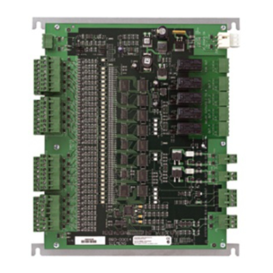
Fig. 1 Product Description The AFI5100 is an Input Point Module used as part of a Siemens integrated access control and security solution. It provides an interface between an Advanced Access Controller (ACC) and up to 32 input devices used to monitor a secure facility. -
Page 6: Expected Installation Time
If being mounted within a cabinet, simply align the AFI5100 base-plate with the holes located on the cabinet backplane and proceed to step 3. It is recommended that you affix the AFI5100 in all four of the mounting loca- tions. - Page 7 (PSU) to the POWER IN port. Ensure the polarity of the connection is made correctly. Check all connections thoroughly. Power can now be applied to the AFI5100 .The following diagram displays the layout and dimensions of the AFI5100 with brace attached: 287mm (11.30") 257mm (10.12")
- Page 8 Input Point Module (AFI5100) The following diagram displays the location of the ports on the AFI5100 : LK 9 LK 10 LOCAL IN OUT RS-485 IN+ IN- OUT+ OUT- The following table provides a brief description of each port: Siemens Building Technologies Fire Safety &...
-
Page 9: Links And Jumpers
Links and Jumpers The following table outlines the link settings for the AFI5100 : Link LK1, LK2 LK4, LK6 LK3, LK5 LK10 LK11 – LK14 Siemens Building Technologies Fire Safety & Security Products Description Links 1 and 2 are used to configure whether Fire Over-ride (FOR) will oper- ate in Enhanced FOR mode or Normal. -
Page 10: Leds
Input Point Module (AFI5100) LEDs The following table describes the operation of the LEDs located on the AFI5100 : POWER ACTIVITY Tx COMMS Rx COMMS Inputs Outputs Fire Each input LED may be in one of two states as indicated by color. -
Page 11: Recommended Cable Specifications
1.10 Programming and Firmware Download The AFI5100 is programmed using the host software application via the ACC, or using the FLN Configurator Field Service Tool application. Please refer to the ap- propriate User’s Guide for more Information. - Page 12 Input Point Module (AFI5100) Siemens Building Technologies A24205-A335-B245.doc Fire Safety & Security Products 02.2005...
- Page 14 Fire & Security Products GmbH & Co. oHG D-76181 Karlsruhe www.sbt.siemens.com Document no. A24205-A335-B245 Edition 02.2005 © 2005 Copyright by Siemens Building Technologies AG Data and design subject to change without notice. Supply subject to availability. Printed in the Federal Republic of Germany on environment-friendly chlorine-free paper.