
Related Manuals for Shure SE30


Summary of Contents for Shure SE30
- Page 1 MODELS SE30 & SE30-2E GATED COMPRESSOR/MIXER OPERATING AND SERVICE MANUAL Copyright 1981, Shure Brothers Inc. Printed in U.S.A. 27A8025 (AK) (90A8103)
- Page 2 Table of Contents List of Illustrations W A R N I N G To reduce the risk of fire or electric shock, do not expose this appliance to rain or extreme moisture.
-
Page 3: Shipping Instructions
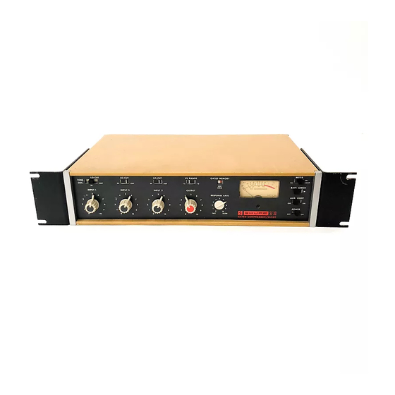
+4 or +6 dBm range switch for VU meter. AC or battery operation with built-in battery supply using readily available 9-volt batteries. *Unless otherwise noted, information applies to both SE30 and SE30-2E models. (Model SE30 shown) Automatic, noiseless switch-over to batteries in the event of ac line failure. - Page 4 -29°C (-20°F) to 74°C (165°F). Weight: 9 Ibs., 13½ oz. (4.5 kg) with batteries and line cord. Operating Voltage: AC Operation: 108-132 volts, 50/60 Hz (SE30 only). 108-132 or 216-264 volts, 50/60 Hz (SE30-2E only). DC Operation: 30 volts ± 20%.
-
Page 5: Rear Panel
(21) function without affecting other operation. Compression Switch: Will disable compression and (22) Gated Memory functions of the SE30, converting it to a high-quality linear mixer and remote amplifier. Stereo Parallel Jack: Phono pin jack allows two units (23) to be synchronized to compress equally the channel sum (L + R) signal. -
Page 7: General Operation
External DC Operation: An external source of dc may be connected to the 30 Volts DC jacks (26) to operate the unit if ac power is not used. The SE30 will draw approxi- mately 12 ma. at 30 volts and must be operated at 30 volts ±... -
Page 8: Operating Considerations
DB Compression meter (7) reading of ap- proximately 10 (lower scale). This is the recommended operating level for the SE30, since the unit will now be able to maintain a substantially constant output level for input reductions of 10 dB and increases of as much as 30 dB. -
Page 9: Theory Of Operation
(12) is provided which may be connected to a similar jack on another SE30 or M67 Mixer. When a Mixer with a mix bus is used in conjunction with the SE30, a compressed output may be obtained from the SE30, and an uncompressed output of the same mixed material will be available from the Mixer. - Page 11 The output of this stage may be shorted to ground by switch S14 to disable compression, or it may be connected in parallel with a similar stage in a second SE30 via its Stereo Parallel jack (J8) so that stereo difference signals will be canceled out and thus not compressed, and the stereo sum will be the controlling signal.
-
Page 16: Schematic Diagram
FOR REPLACEMENT, PURCHASE Q502-Q503 AND Q510-Q511 AS MATCHED PAIRS TIS92M-TIS93M. ORDER REPLACEMENT PARTS UNDER THlS NUMBER WHEN APPLICABLE. IF NO NUMBER IS SHOWN IN THlS COLUMN, ORDER UNDER SHURE PART NUMBER. REPLACEMENT OF THESE PARTS NECESSITATES RECALIBRATION OF UNIT. SEE SERVICE SECTION. - Page 17 FOR REPLACEMENT, PURCHASE Q502-Q503 AND Q510-Q511 AS MATCHED PAIRS TIS92M-TIS93M. ORDER REPLACEMENT PARTS UNDER THIS NUMBER WHEN APPLICABLE. IF NO NUMBER IS SHOWN IN THlS COLUMN, ORDER UNDER SHURE PART NUMBER. REPLACEMENT OF THESE PARTS NECESSITATES RECALIBRATION OF UNIT. SEE SERVICE SECTION.
- Page 18 TEST VOLTAGES, P. C. BOARD TERMINALS TABLE 2A...
- Page 19 TEST VOLTAGES, TRANSISTORS - TABLE 2B...
- Page 20 NOTES TO SCHEMATIC DIAGRAM AND TEST VOLTAGES (Figure 4, Table 2) 1. All capacitors shown in microfarads and 50 volts or more unless otherwise indicated. Electrolytic capac- itors shown in mF X volts. pF = picofarad. 2. All fixed resistors ±10%, ¼ watt unless otherwise shown.
- Page 21 CHASSIS PARTS PLACEMENT FIGURE 5...
-
Page 22: Printed Circuit Board
PRINTED CIRCUIT BOARD 1 PRINTED CIRCUIT BOARD 2 PARTS PLACEMENT FIGURE 6A... - Page 23 PRINTED CIRCUIT BOARD 3 PRINTED CIRCUIT BOARD 4 PARTS PLACEMENT FIGURE 6B...
- Page 24 PRINTED CIRCUIT BOARD 5 PARTS PLACEMENT FIGURE 6C...
-
Page 25: Service Instructions
End plates may be removed for easier access to side- mounted components by removing the remaining Phil- lips screws on each side of the SE30. The end plates may then be removed by pulling straight up. The bottom cover may be removed either with or with- out removing the end plates as above. -
Page 26: Equipment Needed
After positioning one or more boards in this manner, the SE30 may be operated and measurements made. All connections to printed circuit boards are made by push-on terminals crimped to color-coded wires. To... -
Page 27: Vu Meter Calibration
SERVICE INSTRUCTIONS (Cont’d) PROCEDURE: First, the meter (7) must be mechanically set to zero. Turn the Power switch (11) OFF and wait one minute. The meter pointer should rest over the mark at the left-hand end of the scale, left of the -20 VU and 0 dB Compression line. -
Page 28: Operation
(R529) for a 0 VU meter reading. Cali- bration is complete. STEREO SYNCHRONIZATION Two SE30’s may be synchronized to operate together for two-channel stereo applications. With the Stereo Par- allel jacks (23) connected together and the adjustment below performed, the two units will respond equally to the sum (left and right) signal to minimize apparent stereo image shift. - Page 29 4. Grasp the knob and pull it completely out of the front panel. 5. Push the black plastic plug supplied with the SE30 into the hole thus exposed. 6. To permit subsequent control adjustment or replace- ment of the knob, the plug may be released by remov-...
- Page 30 A100A serves as a handle for carrying the SE30, as a cover for the front panel, and as a tilt stand for position- ing the SE30 at an angle for easy reading of the con- trols and meters. The A100A is easily switched from...